EP0819877A2 - Dispositif de commande d'un mitigeur à levier unique - Google Patents
Dispositif de commande d'un mitigeur à levier unique Download PDFInfo
- Publication number
- EP0819877A2 EP0819877A2 EP97111577A EP97111577A EP0819877A2 EP 0819877 A2 EP0819877 A2 EP 0819877A2 EP 97111577 A EP97111577 A EP 97111577A EP 97111577 A EP97111577 A EP 97111577A EP 0819877 A2 EP0819877 A2 EP 0819877A2
- Authority
- EP
- European Patent Office
- Prior art keywords
- stop
- actuating device
- handle
- stop button
- lever
- Prior art date
- Legal status (The legal status is an assumption and is not a legal conclusion. Google has not performed a legal analysis and makes no representation as to the accuracy of the status listed.)
- Withdrawn
Links
Images


Classifications
-
- F—MECHANICAL ENGINEERING; LIGHTING; HEATING; WEAPONS; BLASTING
- F16—ENGINEERING ELEMENTS AND UNITS; GENERAL MEASURES FOR PRODUCING AND MAINTAINING EFFECTIVE FUNCTIONING OF MACHINES OR INSTALLATIONS; THERMAL INSULATION IN GENERAL
- F16K—VALVES; TAPS; COCKS; ACTUATING-FLOATS; DEVICES FOR VENTING OR AERATING
- F16K31/00—Actuating devices; Operating means; Releasing devices
- F16K31/44—Mechanical actuating means
- F16K31/60—Handles
- F16K31/605—Handles for single handle mixing valves
-
- F—MECHANICAL ENGINEERING; LIGHTING; HEATING; WEAPONS; BLASTING
- F16—ENGINEERING ELEMENTS AND UNITS; GENERAL MEASURES FOR PRODUCING AND MAINTAINING EFFECTIVE FUNCTIONING OF MACHINES OR INSTALLATIONS; THERMAL INSULATION IN GENERAL
- F16K—VALVES; TAPS; COCKS; ACTUATING-FLOATS; DEVICES FOR VENTING OR AERATING
- F16K11/00—Multiple-way valves, e.g. mixing valves; Pipe fittings incorporating such valves
- F16K11/02—Multiple-way valves, e.g. mixing valves; Pipe fittings incorporating such valves with all movable sealing faces moving as one unit
- F16K11/06—Multiple-way valves, e.g. mixing valves; Pipe fittings incorporating such valves with all movable sealing faces moving as one unit comprising only sliding valves, i.e. sliding closure elements
- F16K11/078—Multiple-way valves, e.g. mixing valves; Pipe fittings incorporating such valves with all movable sealing faces moving as one unit comprising only sliding valves, i.e. sliding closure elements with pivoted and linearly movable closure members
- F16K11/0782—Single-lever operated mixing valves with closure members having flat sealing faces
-
- F—MECHANICAL ENGINEERING; LIGHTING; HEATING; WEAPONS; BLASTING
- F16—ENGINEERING ELEMENTS AND UNITS; GENERAL MEASURES FOR PRODUCING AND MAINTAINING EFFECTIVE FUNCTIONING OF MACHINES OR INSTALLATIONS; THERMAL INSULATION IN GENERAL
- F16K—VALVES; TAPS; COCKS; ACTUATING-FLOATS; DEVICES FOR VENTING OR AERATING
- F16K35/00—Means to prevent accidental or unauthorised actuation
- F16K35/02—Means to prevent accidental or unauthorised actuation to be locked or disconnected by means of a pushing or pulling action
- F16K35/022—Means to prevent accidental or unauthorised actuation to be locked or disconnected by means of a pushing or pulling action the locking mechanism being actuated by a separate actuating element
- F16K35/025—Means to prevent accidental or unauthorised actuation to be locked or disconnected by means of a pushing or pulling action the locking mechanism being actuated by a separate actuating element said actuating element being operated manually (e.g. a push-button located in the valve actuator)
-
- Y—GENERAL TAGGING OF NEW TECHNOLOGICAL DEVELOPMENTS; GENERAL TAGGING OF CROSS-SECTIONAL TECHNOLOGIES SPANNING OVER SEVERAL SECTIONS OF THE IPC; TECHNICAL SUBJECTS COVERED BY FORMER USPC CROSS-REFERENCE ART COLLECTIONS [XRACs] AND DIGESTS
- Y10—TECHNICAL SUBJECTS COVERED BY FORMER USPC
- Y10T—TECHNICAL SUBJECTS COVERED BY FORMER US CLASSIFICATION
- Y10T137/00—Fluid handling
- Y10T137/8593—Systems
- Y10T137/86493—Multi-way valve unit
- Y10T137/86549—Selective reciprocation or rotation
-
- Y—GENERAL TAGGING OF NEW TECHNOLOGICAL DEVELOPMENTS; GENERAL TAGGING OF CROSS-SECTIONAL TECHNOLOGIES SPANNING OVER SEVERAL SECTIONS OF THE IPC; TECHNICAL SUBJECTS COVERED BY FORMER USPC CROSS-REFERENCE ART COLLECTIONS [XRACs] AND DIGESTS
- Y10—TECHNICAL SUBJECTS COVERED BY FORMER USPC
- Y10T—TECHNICAL SUBJECTS COVERED BY FORMER US CLASSIFICATION
- Y10T137/00—Fluid handling
- Y10T137/8593—Systems
- Y10T137/86493—Multi-way valve unit
- Y10T137/86815—Multiple inlet with single outlet
Definitions
- the invention relates to an actuating device for a single-lever mixer valve, in particular for water pipes in the sanitary area, with a handle which can be moved in two degrees of freedom and which is connected to a valve member for determining the mixing ratio and the total flow rate via a steep lever, with stop means being provided to limit the movement of the valve member which is at least limited by a surmountable sling.
- a surmountable sling Such a device is known from EP 0 662 577 A1.
- surmountable stop means are provided in the form of lugs protruding resiliently into the swivel path of the adjusting lever, which can be overcome by the user when actuated by an increased force input into the handle.
- an actuating device for a mixing valve is known from EP 0 426 639 A1, in which the stop for limiting the total flow rate can be overcome by pressing or pulling the entire handle, that is to say in a third degree of freedom of the handle.
- the invention is based on the object in the preamble of claim 1 specified facility under Maintaining a rigid connection between the control lever and handle so that the surmountable Stop by the user through a separate operation is solvable. It is part of the task to make an over for a relatively long period of time, to create low-wear valve actuation devices, with the saving of water and energy becomes possible.
- This object is achieved in that a stop button on the handle in the area of the handle body is provided with which the sling for Limitation of the total flow rate can be solved by the user is.
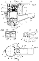
- a single-lever mixer valve 1 for a washstand (not shown in the drawing) is shown.
- inlet pipes 13, 14 for cold and hot water are connected, which are connected via an insert 17 to a mixer valve 10 arranged in the single-lever mixer valve 1.
- the mixed water that can be generated in the mixing valve 10 is discharged via a channel 171 into an outlet arm of the single-lever mixer valve. At the end region of the outlet arm 12, the water can then emerge as a free jet from the single-lever mixer valve 1 via an outlet nozzle 121.
- the individual valve elements of the mixing valve 10 are encapsulated in a cartridge housing 102, the cartridge housing 102 being screwed to the single-lever mixer valve 1 together with the insert 17 by means of fastening screws 101.
- an adjusting lever 11 which can be rotated about a central axis 100 and pivotable about an axis 110 arranged perpendicular to the central axis 100, is led out on the end face.
- a handle 2 is attached to the adjusting lever 11 with a lever head 20 having a circumferential collar, on which a handle body 200 is arranged laterally for operation. The handle 2 is secured in the inserted position by a fastening screw 26.
- the total flow rate of the water in the mixing valve 10 is determined as a function of the pivoting angle.
- the mixing ratio of cold and hot water and thus the temperature of the emerging mixed water in the mixing valve 10 can be set depending on the angle of rotation.
- a fastening bolt 15 is also provided, with which the single-lever mixer valve 1 can be fastened in a known manner to the washstand or sink with the aid of washers (not shown) and a nut.
- a stop button 3 is also arranged in the handle 2.
- the stop button 3 consists of a rocker 30 which is approximately U-shaped in cross section, on one end region of which a curvature 36 is formed for actuation, while a stop body 31 is formed on the opposite end region, as is particularly the case in FIGS. 1 and Fig. 4 can be seen.
- the rocker 30 is in this case provided with an offset 37 at the end region on which the curvature 36 is arranged, an apron 35 being additionally formed in this region.
- a tab 33 is formed on each of the U-legs, on the end region of which cylindrical pins 331 are formed, which have a bevel 332 on the projecting end face, as can be seen in particular from FIG.
- the stop button 3 with the pins 331 fits into a trough-shaped receptacle 22 of the lever head 20, as can be seen in particular from FIG. 3.
- the tabs 33 are resilient so that the stop button 33 can be blown into the receptacle 22.
- the pins 331 engage in radial openings 221 in the lever head 20.
- the bevels 332 are formed on the pins 331, and corresponding bevels 222 are also provided on the lever head 20, as can be seen in particular from FIG. 3 of the drawing.
- the front area of the stop button 3 with the spherical curvature 36 is received by a recess 23 in the handle body 200, while the stop body 31 is passed through an opening 24 in the lever head 20 and interacts with a stop ring 5 arranged on a reduced-diameter attachment of the mixing valve cartridge 102 .
- a spring 32 is arranged in the lever head 20 in a recess, which is covered by the apron 35 from the front.
- a cover 25 is provided to cover the rocker 30 of the stop button 3, which is provided with locking tongues 251.
- the latching tongues 251 are resilient and engage in the plug-in position through the opening 24 and thus hold the cover 25 on the lever head 20.
- the rocker 30 is provided with an opening 34 which is placed in such a way that after removal of the cover 25 the fastening screw 26 is accessible for fastening the handle 2 to the adjusting lever 11.
- the stop button 3, consisting of the curvature 36, the rocker 30, the stop body 31, the apron 35 and the tabs 33 with the pin 331, is made in one piece from plastic by injection molding.
- the cover 25 with the locking tongues 251 is also made of plastic by injection molding.
- the cartridge housing 102 with the insert 17 is arranged in the single-lever mixer valve 1 in such a rotational position that the handle 2 in the cold water stop position of the mixer valve 10 is arranged parallel to the outlet arm 12 of the single-lever mixer valve 1, as can be seen in particular from FIG. 2 of the drawing .
- This also enables energy savings to be achieved, since unintentional tapping of hot water can be largely avoided.
- an adjusting screw can be arranged in the stop body 31, with which the stop position is adjustable.
- the set screw can in this case be arranged with a thread in the stop body 31, with the stop position then being individually adjustable to approximately 50% of the maximum discharge amount by correspondingly unscrewing it against the lever head 20 (pin 21).
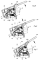
- the actuating device of the single-lever mixer valve 1 described above has the following function: In the position of the handle 2 shown in FIG. 1, the mixing valve 10 is in the cold water position in the shut-off position. 5, if the handle 2 is raised in the direction of the arrow, the stop body 31 comes to rest on the inner wall of the stop ring 5 when an opening degree of approximately 50% of the maximum possible total flow rate has been reached. A further pivoting movement of the handle 2 is prevented by the stop body 31, which bears positively on the inside of the stop ring 5.
- the stop button 3 on the curvature 36 is pressed by the user in the direction of the arrow against the force of the spring 32, so that the stop body 31 formed on the opposite end region of the rocker 30 is pivoted out of the region of the stop ring 5, so that the effective stop is released in half the opening degree and the user can pivot the handle 2 into the maximum opening position, as shown in FIG. 7.
- the stop body slides on the end face of the stop ring, so that the curvature 36 remains in the pressed-in position. If the handle 2 is now moved back against the direction of the arrow in FIG. 7, the spring 32 presses the stop button 3 with the stop body 31 after throttling by 50% back into its stop position - as shown in FIG.
- the mixed water temperature can be increasingly adjusted from the cold water position to the hot water position and back by rotating the handle 2 about the central axis 100.
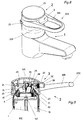
- a modified single-lever mixer valve 1 is shown.
- the handle body 200 of the handle 2 is in this case designed as a bracket which is formed by two arms 201 running in parallel, which are connected to one another in an arc at the projecting end region and, on the other hand, are introduced tangentially into the lever head 20.
- the stop button 3 is formed between the two arms 201 on the side region of the lever head 20.
- the stop button 3 corresponds essentially to that in the exemplary embodiments 1 to 7, but no special curvature 36 is provided and the front end of the rocker 30 with the apron 35 forms the actuation area.
- the stop button 3 cooperates with a temperature stop ring 4, the lever head 20 with a pin 21 having a square or rectangular cross section engaging in a swivel path 41, so that during a rotary movement about the central axis 100 the temperature stop ring 4 executes a rotary movement synchronously with the valve member.
- the temperature stop ring 4 is arranged on a plug ring 42 such that it can be rotated to a limited extent, the plug ring 42 being able to be attached in a rotationally fixed manner in various rotational positions on the reduced-diameter attachment of the handle 2, as is known from German patent DE 36 07 349 C2.
- the mixing valve 10 is arranged in the single-lever mixing valve 1 so that in a middle mixing position of the mixing valve 10, the handle 2 with the handle body 200 is arranged parallel to the outlet arm 12 of the single-lever mixing valve 1.
- the mixing valve 10 can also be arranged in the single-lever mixing valve 1 such that the handle 2 with the handle body 200 is arranged parallel to the outlet arm 12 in the cold water position of the mixing valve 10.
- this single-lever mixer valve 1 corresponds otherwise the one shown in Figs. 1 to 7.
- the stop button 3 is designed with a slide 300.
- the slide 300 is slidably mounted on the lever head 20 parallel to the arms 201.
- the area of attack for the actuation is formed by the apron 35 on the end face, on which the spring 32 is supported on the other hand.
- a snap hook 351 is also formed on the apron 35, which holds the stop button 3 in the pressed-in position, as shown in FIG. 12. During the closing process, the snap hook 351 is deflected from its detent position by an edge 43 of the temperature stop ring 4, so that the spring 32 then pushes the stop button 3 out of the lever head 20 again.
- the stop body 31 cooperates with its projecting end face with an end face of the temperature stop ring 4.
- the actuating device of the single-lever mixer valve 1 described above has the following function: The mixing valve 10 is in the position of the handle 2 shown in FIG. 10 in the closed position, the stop body 31 being in its stop position. If the handle 2 on the handle body 200 is now raised, the end face of the stop body 31 comes to rest on the end face of the temperature stop ring 4 in the half-open position of the mixing valve 10 and prevents a further opening movement, as shown in FIG. 11.
- the snap hook 31 reaches its latching position and holds the stop button 3 in the pressed-in position, as shown in FIG. 12.
- the handle 2 on the handle body 200 can now be raised further until the maximum opening position of the mixing valve 10 is reached, as shown in FIG. 12. If the mixing valve 10 is then moved back into its closed position with the handle body 200, the snap hook 351 comes to rest with its side region on the edge 43 of the temperature stop ring 4 and is thereby deflected out of its detent position, so that the spring 32 pushes the stop button 3 with the Stop body 31 pushes back into its stop position, as shown in FIGS. 10 and 11. A total flow rate setting of approximately 10 to 100% is possible in the locking position.
- FIGs 13 to 18 of the drawing is one of the Figures 1 to 7 modified training shown.
- the stop button 3 is here with the rocker 30 on the front arranged on the lever head 20, being at the Rocker 30 integrally formed an arm 38 with a curved head 381 is.
- the end face of the lever head 20 and a Part of the handle body 200 are here with a cover 25 provided, as can be seen from Figures 13 and 14 is.
- In the cover 25 is in the range of Handle body 200 an opening 252 formed by an elastomer cover 6 is closed.
- the elastomer cover 6 is of a dome-shaped bulge Membrane 60 with reinforcing ribs arranged crosswise 61 and a snap ring 62 with locking lugs 63, as is shown in particular in FIGS. 16 and 17 can be seen.
- the membrane 60 is here with the Snap ring 62 in two-component injection molding (Composite injection molding) made in one piece, the Membrane 60 made of a thermoplastic elastomer and the snap ring 62 is made of polypropylene.
- the arm 38 of the rocker 30 projects with its head 381 into it Center of the opening 252 and is with the cover attached 25 on the inside in the area of the reinforcing ribs 61 on.
- the rocker 30 is counter the force of the spring 32 guided on a mandrel 39 deflected and the stop body 31 from its stop position swung out, so that the full opening of the mixing valve is possible, as it is already in Embodiment according to Figures 1 to 7 described is.
- the stop button 3 prevents so that a trouble-free, low-wear operation over a relatively long time Period is guaranteed.
- stop ring 5 with three different stop areas 51, 52, 53 are provided, as is shown in particular in FIG 18 and 19 can be seen.
- the stop ring 5 can here with its teeth 54 on the mixing valve 10 plugged into the desired rotational position be so that one of the three differently graded Stop areas 51,52,53 can be selected.
Landscapes
- Engineering & Computer Science (AREA)
- General Engineering & Computer Science (AREA)
- Mechanical Engineering (AREA)
- Multiple-Way Valves (AREA)
- Mechanically-Actuated Valves (AREA)
- Preventing Unauthorised Actuation Of Valves (AREA)
- Domestic Plumbing Installations (AREA)
Applications Claiming Priority (2)
| Application Number | Priority Date | Filing Date | Title |
|---|---|---|---|
| DE19628937 | 1996-07-18 | ||
| DE19628937A DE19628937A1 (de) | 1996-07-18 | 1996-07-18 | Betätigungseinrichtung für ein Einhebelmischventil |
Publications (2)
| Publication Number | Publication Date |
|---|---|
| EP0819877A2 true EP0819877A2 (fr) | 1998-01-21 |
| EP0819877A3 EP0819877A3 (fr) | 1998-08-05 |
Family
ID=7800142
Family Applications (1)
| Application Number | Title | Priority Date | Filing Date |
|---|---|---|---|
| EP97111577A Withdrawn EP0819877A3 (fr) | 1996-07-18 | 1997-07-09 | Dispositif de commande d'un mitigeur à levier unique |
Country Status (9)
| Country | Link |
|---|---|
| US (1) | US5992457A (fr) |
| EP (1) | EP0819877A3 (fr) |
| JP (1) | JPH1072854A (fr) |
| CZ (1) | CZ231097A3 (fr) |
| DE (1) | DE19628937A1 (fr) |
| ES (1) | ES1037835Y (fr) |
| HU (1) | HUP9701171A3 (fr) |
| PL (1) | PL321221A1 (fr) |
| SK (1) | SK95897A3 (fr) |
Cited By (4)
| Publication number | Priority date | Publication date | Assignee | Title |
|---|---|---|---|---|
| EP0933573A3 (fr) * | 1998-01-30 | 2000-12-20 | Friedrich Grohe AG & Co. KG | Dispositif de commande d'un robinet sanitaire |
| EP1055781A3 (fr) * | 1999-05-25 | 2002-03-13 | Boehm, Hans-Georg, Dr. rer. nat. | Robinet mitigeur à deux pas |
| DE102009001015A1 (de) | 2009-02-19 | 2010-09-02 | Georg-August-Universität Göttingen Stiftung Öffentlichen Rechts Universitätsmedizin | Vorrichtung zur variablen Begrenzung eines Medienflusses aus Mischbatterien |
| WO2015131957A1 (fr) * | 2014-03-07 | 2015-09-11 | Linde Aktiengesellschaft | Levier pour soupape actionnée par levier |
Families Citing this family (20)
| Publication number | Priority date | Publication date | Assignee | Title |
|---|---|---|---|---|
| DE10261266B3 (de) * | 2002-12-27 | 2004-07-29 | Hansa Metallwerke Ag | Sanitäre Auslaufarmatur, insbesondere Einhebelmischer |
| ITMI20030305A1 (it) * | 2003-02-20 | 2004-08-21 | Ugo Pizzi | Rubinetto miscelatore monocomando con miglorata regolazione del flusso. |
| ITMI20042559A1 (it) * | 2004-12-30 | 2005-03-30 | Piero Cattaneo | Cartuccia per la regolazione della portata e per la miscelazione dei flussi di acqua in rubinetti in genere |
| ES1059642Y (es) | 2005-02-10 | 2005-09-01 | Fagor S Coop | Valvula rotatoria montada en un aparato de coccion multi-gas |
| CZ302563B6 (cs) * | 2006-03-01 | 2011-07-13 | Caha@Milan | Vodovodní páková baterie se stavitelným dorazem otevírací páky |
| US8578966B2 (en) | 2006-07-28 | 2013-11-12 | Masco Corporation Of Indiana | Mixing valve |
| US7753074B2 (en) | 2006-07-28 | 2010-07-13 | Masco Corporation Of Indiana | Mixing valve |
| US8109294B2 (en) * | 2007-01-31 | 2012-02-07 | Moen Incorporated | Valve cartridge with integral stop |
| EP2171333A4 (fr) * | 2007-06-25 | 2013-02-20 | Little Guard Ltd | Limiteur pour robinets d'eau équipés de poignées de type levier |
| USD623724S1 (en) | 2007-10-03 | 2010-09-14 | Masco Corporation Of Indiana | Single handle valve cartridge |
| ES1069849Y (es) | 2008-12-19 | 2009-09-14 | Coprecitec Sl | "valvula de regulacion para un aparato de coccion a gas" |
| US8347905B1 (en) * | 2010-04-20 | 2013-01-08 | Stirtz Ronald H | Energy saving faucet |
| CN102563194B (zh) * | 2011-12-23 | 2013-09-04 | 厦门松霖科技有限公司 | 按钮切换水路阀组 |
| US20130248011A1 (en) * | 2012-03-21 | 2013-09-26 | Guo Yuan Hardware Co., Ltd. | Faucet control valve |
| US9841121B2 (en) * | 2012-09-24 | 2017-12-12 | Eran Ben-Dor | Nonlinear transmission rate between operating handle and operated mechanism |
| US9103102B1 (en) * | 2014-04-16 | 2015-08-11 | SensiTap, LLC | Water-saving faucet |
| CN204704428U (zh) * | 2015-04-18 | 2015-10-14 | 厦门建霖工业有限公司 | 一种双出水龙头 |
| JP6651247B2 (ja) * | 2015-09-04 | 2020-02-19 | Sanei株式会社 | 水栓用ハンドルの水浸入防止構造並びに水栓用レバーハンドル |
| DE102020124930A1 (de) * | 2020-09-24 | 2022-03-24 | Oras Oy | Einstellelement zum Einstellen einer maximalen Wasserdurchflusseinstellungeines Hebelhahnventils, Hebelhahnventil und sanitärer Hebelhahn |
| EP4553242A1 (fr) * | 2023-11-13 | 2025-05-14 | Kohler Co. | Robinet à poignées interchangeables |
Citations (2)
| Publication number | Priority date | Publication date | Assignee | Title |
|---|---|---|---|---|
| EP0426639A1 (fr) | 1989-10-31 | 1991-05-08 | Staar Societe Anonyme | Mitigeur à levier unique |
| EP0662577A1 (fr) | 1993-11-30 | 1995-07-12 | Friedrich Grohe Aktiengesellschaft | Dispositif de commande pour une vanne mitigeuse à levier unique |
Family Cites Families (9)
| Publication number | Priority date | Publication date | Assignee | Title |
|---|---|---|---|---|
| DE3364916D1 (en) * | 1982-05-28 | 1986-09-04 | Simeg Brevet Ag | Single handle hot and cold water mixing and flow control tap |
| DE3337968A1 (de) * | 1983-10-19 | 1985-05-02 | Friedrich Grohe Armaturenfabrik Gmbh & Co, 5870 Hemer | Handhebel fuer eingriffmischventile |
| DE3402103C1 (de) * | 1984-01-21 | 1985-03-28 | Heinrich Schulte & Sohn Gmbh & Co Kg, 5860 Iserlohn | Einhebel-Mischbatterie |
| FI70994C (fi) * | 1985-01-24 | 1986-10-27 | Oras Oy | Engreppskran |
| DE3607349C2 (de) * | 1986-03-06 | 1995-07-20 | Grohe Armaturen Friedrich | Betätigungseinrichtung für Eingriffmischventile |
| EP0578310B1 (fr) * | 1992-07-07 | 1996-12-04 | Caspro, S.A. | Mitigeur à commande unique |
| FI94167C (fi) * | 1993-09-14 | 1995-07-25 | Oras Oy | Yksiotehana |
| US5363880A (en) * | 1994-01-24 | 1994-11-15 | Hsieh Yung Li | Hot/cold water mixing faucet with water temperature control |
| DE4431435A1 (de) * | 1994-09-03 | 1996-03-07 | Grohe Armaturen Friedrich | Einhebelmischventil |
-
1996
- 1996-07-18 DE DE19628937A patent/DE19628937A1/de not_active Ceased
-
1997
- 1997-06-23 US US08/881,019 patent/US5992457A/en not_active Expired - Fee Related
- 1997-07-09 HU HU9701171A patent/HUP9701171A3/hu unknown
- 1997-07-09 EP EP97111577A patent/EP0819877A3/fr not_active Withdrawn
- 1997-07-14 ES ES09701924U patent/ES1037835Y/es not_active Expired - Fee Related
- 1997-07-15 SK SK958-97A patent/SK95897A3/sk unknown
- 1997-07-17 PL PL97321221A patent/PL321221A1/xx unknown
- 1997-07-17 JP JP9192686A patent/JPH1072854A/ja active Pending
- 1997-07-18 CZ CZ972310A patent/CZ231097A3/cs unknown
Patent Citations (2)
| Publication number | Priority date | Publication date | Assignee | Title |
|---|---|---|---|---|
| EP0426639A1 (fr) | 1989-10-31 | 1991-05-08 | Staar Societe Anonyme | Mitigeur à levier unique |
| EP0662577A1 (fr) | 1993-11-30 | 1995-07-12 | Friedrich Grohe Aktiengesellschaft | Dispositif de commande pour une vanne mitigeuse à levier unique |
Cited By (4)
| Publication number | Priority date | Publication date | Assignee | Title |
|---|---|---|---|---|
| EP0933573A3 (fr) * | 1998-01-30 | 2000-12-20 | Friedrich Grohe AG & Co. KG | Dispositif de commande d'un robinet sanitaire |
| EP1055781A3 (fr) * | 1999-05-25 | 2002-03-13 | Boehm, Hans-Georg, Dr. rer. nat. | Robinet mitigeur à deux pas |
| DE102009001015A1 (de) | 2009-02-19 | 2010-09-02 | Georg-August-Universität Göttingen Stiftung Öffentlichen Rechts Universitätsmedizin | Vorrichtung zur variablen Begrenzung eines Medienflusses aus Mischbatterien |
| WO2015131957A1 (fr) * | 2014-03-07 | 2015-09-11 | Linde Aktiengesellschaft | Levier pour soupape actionnée par levier |
Also Published As
| Publication number | Publication date |
|---|---|
| ES1037835Y (es) | 1998-11-01 |
| HUP9701171A2 (hu) | 1999-01-28 |
| HU9701171D0 (en) | 1997-08-28 |
| DE19628937A1 (de) | 1998-01-22 |
| HUP9701171A3 (en) | 1999-03-29 |
| EP0819877A3 (fr) | 1998-08-05 |
| JPH1072854A (ja) | 1998-03-17 |
| SK95897A3 (en) | 1998-04-08 |
| PL321221A1 (en) | 1998-01-19 |
| US5992457A (en) | 1999-11-30 |
| CZ231097A3 (cs) | 1999-02-17 |
| ES1037835U (es) | 1998-04-16 |
Similar Documents
| Publication | Publication Date | Title |
|---|---|---|
| EP0819877A2 (fr) | Dispositif de commande d'un mitigeur à levier unique | |
| AT390490B (de) | Sanitaeres wasserventil mit in einem gehaeuse parallel zueinanderliegenden ventilscheiben | |
| EP2041375B1 (fr) | Embout de sortie | |
| EP0149477B1 (fr) | Levier de commande pour robinet inverseur | |
| EP1736695B1 (fr) | Vanne, notamment pour une robinetterie sanitaire | |
| EP2498655B1 (fr) | Pomme de douche | |
| DE20306719U1 (de) | Sprühkappe | |
| EP0844423A2 (fr) | Mitigeur à monocommande. | |
| EP0801255A2 (fr) | Tiroir rotative | |
| EP0745798B1 (fr) | Poignée pour robinet sanitaire | |
| EP0621427B2 (fr) | Vanne de réglage de débit | |
| EP1268080A2 (fr) | Vanne multivoie pour robinetterie sanitaire | |
| EP0061563B1 (fr) | Batterie bain-douche | |
| DE10138304A1 (de) | Einhebelventil | |
| DE3700927C2 (fr) | ||
| DE3509649A1 (de) | Mischbatterie | |
| DE3426480C2 (fr) | ||
| DE3222968A1 (de) | Handbrause mit umstellbarem ventil | |
| DE3509648C2 (de) | Mischbatterie | |
| EP0730715A1 (fr) | Robinet pour installation sanitaire | |
| EP0195999B1 (fr) | Mitigeur | |
| DE4005289C2 (fr) | ||
| EP1083373A2 (fr) | Robinet-vanne d'eau | |
| DE19646736A1 (de) | Mischpatrone für Einhandmischbatterien | |
| EP1329560B1 (fr) | Armature d'eau |
Legal Events
| Date | Code | Title | Description |
|---|---|---|---|
| PUAI | Public reference made under article 153(3) epc to a published international application that has entered the european phase |
Free format text: ORIGINAL CODE: 0009012 |
|
| AK | Designated contracting states |
Kind code of ref document: A2 Designated state(s): AT BE CH DE DK ES FI FR GB IT LI NL SE |
|
| AX | Request for extension of the european patent |
Free format text: AL;LT;LV;SI |
|
| PUAL | Search report despatched |
Free format text: ORIGINAL CODE: 0009013 |
|
| AK | Designated contracting states |
Kind code of ref document: A3 Designated state(s): AT BE CH DE DK ES FI FR GB GR IE IT LI LU MC NL PT SE |
|
| AX | Request for extension of the european patent |
Free format text: AL;LT;LV;SI |
|
| 17P | Request for examination filed |
Effective date: 19981219 |
|
| AKX | Designation fees paid |
Free format text: AT BE CH DE DK ES FI FR GB IT LI NL SE |
|
| RBV | Designated contracting states (corrected) |
Designated state(s): AT BE CH DE DK ES FI FR GB IT LI NL SE |
|
| RAP1 | Party data changed (applicant data changed or rights of an application transferred) |
Owner name: FRIEDRICH GROHE AG & CO. KG |
|
| 17Q | First examination report despatched |
Effective date: 20001222 |
|
| STAA | Information on the status of an ep patent application or granted ep patent |
Free format text: STATUS: THE APPLICATION IS DEEMED TO BE WITHDRAWN |
|
| 18D | Application deemed to be withdrawn |
Effective date: 20030201 |