EP0819881A2 - Steuervorrichtung für Lichtgitter - Google Patents
Steuervorrichtung für Lichtgitter Download PDFInfo
- Publication number
- EP0819881A2 EP0819881A2 EP97203118A EP97203118A EP0819881A2 EP 0819881 A2 EP0819881 A2 EP 0819881A2 EP 97203118 A EP97203118 A EP 97203118A EP 97203118 A EP97203118 A EP 97203118A EP 0819881 A2 EP0819881 A2 EP 0819881A2
- Authority
- EP
- European Patent Office
- Prior art keywords
- signal
- controller
- output control
- detector
- photosources
- Prior art date
- Legal status (The legal status is an assumption and is not a legal conclusion. Google has not performed a legal analysis and makes no representation as to the accuracy of the status listed.)
- Withdrawn
Links
Images


Classifications
-
- H—ELECTRICITY
- H01—ELECTRIC ELEMENTS
- H01H—ELECTRIC SWITCHES; RELAYS; SELECTORS; EMERGENCY PROTECTIVE DEVICES
- H01H47/00—Circuit arrangements not adapted to a particular application of the relay and designed to obtain desired operating characteristics or to provide energising current
- H01H47/002—Monitoring or fail-safe circuits
-
- F—MECHANICAL ENGINEERING; LIGHTING; HEATING; WEAPONS; BLASTING
- F16—ENGINEERING ELEMENTS AND UNITS; GENERAL MEASURES FOR PRODUCING AND MAINTAINING EFFECTIVE FUNCTIONING OF MACHINES OR INSTALLATIONS; THERMAL INSULATION IN GENERAL
- F16P—SAFETY DEVICES IN GENERAL; SAFETY DEVICES FOR PRESSES
- F16P3/00—Safety devices acting in conjunction with the control or operation of a machine; Control arrangements requiring the simultaneous use of two or more parts of the body
- F16P3/12—Safety devices acting in conjunction with the control or operation of a machine; Control arrangements requiring the simultaneous use of two or more parts of the body with means, e.g. feelers, which in case of the presence of a body part of a person in or near the danger zone influence the control or operation of the machine
- F16P3/14—Safety devices acting in conjunction with the control or operation of a machine; Control arrangements requiring the simultaneous use of two or more parts of the body with means, e.g. feelers, which in case of the presence of a body part of a person in or near the danger zone influence the control or operation of the machine the means being photocells or other devices sensitive without mechanical contact
- F16P3/144—Safety devices acting in conjunction with the control or operation of a machine; Control arrangements requiring the simultaneous use of two or more parts of the body with means, e.g. feelers, which in case of the presence of a body part of a person in or near the danger zone influence the control or operation of the machine the means being photocells or other devices sensitive without mechanical contact using light grids
-
- G—PHYSICS
- G01—MEASURING; TESTING
- G01V—GEOPHYSICS; GRAVITATIONAL MEASUREMENTS; DETECTING MASSES OR OBJECTS; TAGS
- G01V8/00—Prospecting or detecting by optical means
- G01V8/10—Detecting, e.g. by using light barriers
- G01V8/20—Detecting, e.g. by using light barriers using multiple transmitters or receivers
-
- G—PHYSICS
- G06—COMPUTING OR CALCULATING; COUNTING
- G06F—ELECTRIC DIGITAL DATA PROCESSING
- G06F11/00—Error detection; Error correction; Monitoring
- G06F11/22—Detection or location of defective computer hardware by testing during standby operation or during idle time, e.g. start-up testing
- G06F11/26—Functional testing
- G06F11/261—Functional testing by simulating additional hardware, e.g. fault simulation
-
- G—PHYSICS
- G08—SIGNALLING
- G08B—SIGNALLING SYSTEMS, e.g. PERSONAL CALLING SYSTEMS; ORDER TELEGRAPHS; ALARM SYSTEMS
- G08B13/00—Burglar, theft or intruder alarms
- G08B13/18—Actuation by interference with heat, light, or radiation of shorter wavelength; Actuation by intruding sources of heat, light, or radiation of shorter wavelength
- G08B13/181—Actuation by interference with heat, light, or radiation of shorter wavelength; Actuation by intruding sources of heat, light, or radiation of shorter wavelength using active radiation detection systems
- G08B13/183—Actuation by interference with heat, light, or radiation of shorter wavelength; Actuation by intruding sources of heat, light, or radiation of shorter wavelength using active radiation detection systems by interruption of a radiation beam or barrier
-
- G—PHYSICS
- G06—COMPUTING OR CALCULATING; COUNTING
- G06F—ELECTRIC DIGITAL DATA PROCESSING
- G06F11/00—Error detection; Error correction; Monitoring
- G06F11/07—Responding to the occurrence of a fault, e.g. fault tolerance
- G06F11/0703—Error or fault processing not based on redundancy, i.e. by taking additional measures to deal with the error or fault not making use of redundancy in operation, in hardware, or in data representation
- G06F11/0751—Error or fault detection not based on redundancy
- G06F11/0754—Error or fault detection not based on redundancy by exceeding limits
- G06F11/0757—Error or fault detection not based on redundancy by exceeding limits by exceeding a time limit, i.e. time-out, e.g. watchdogs
Definitions
- This invention relates to photodetection systems and related circuitry which, upon the occurrence of a specified event, generate an output control signal.
- this invention relates to a system of interrelated electrical, optical, and mechanical modules designed and deployed so as to sense the intrusion of an opaque object into a controlled space and upon such sensing to immediately initiate a machine-stopping or machine-starting sequence.
- this invention relates to improved light curtain systems manifesting increased reliability and accuracy and imperviousness to spurious signals.
- this invention relates to a microcontroller-based light curtain system containing an integrated collection of improvements over traditional light current systems. These improvements include provisions for continual self-testing during operation ⁇ including self-monitoring for deliberately simulated false events ⁇ as well as the means to react to detected defects in a manner safeguarding those depending on the safety switch nature of the light curtain.
- a control signal that triggers other mechanisms.
- This type of photodetection system is then an area light switch, since it generates an output control signal whenever anything opaque to the light penetrates the area defined by the light.
- the present invention addresses the dependability requirement and relates most directly to the safe operation of machine-guarding light curtains comprising: 1) an array of discrete photosources, each directing light onto a particular member of 2) a matching array of discrete photodetectors which are tied into 3) circuitry capable of producing a control signal that opens 4) an output control device whenever the flux of photosource light incident on one of the photodetectors decreases by more than some specific amount.
- the output control device most commonly an electromechanical relay ⁇ is in turn part of a simple current loop emanating from the machine to be controlled; the interruption of that current loop initiates the machine's stopping mechanism.
- the light curtain system (including the relay) is often viewed as a "switch.”
- Such light curtains serve as switch elements in control systems commonly used to halt (or, sometimes, to activate ) machinery when an opaque object ⁇ e.g., a hand ⁇ moves between the photosource array and the photodetector array.
- an opaque object e.g., a hand ⁇ moves between the photosource array and the photodetector array.
- the present invention will be seen to have applications wherever both sensing speed and high dependability are at a premium, it is sufficient for present purposes to describe it in the context of prior art related to machine-guarding light curtains.
- the speed with which a light curtain system initiates a machine's stopping sequence depends largely on the type of components used, how quickly the circuit processes information, and how quickly the relay opens upon receiving the appropriate signal.
- the factor determining how quickly the relay receives its "opening" signal is the method used to enhance system dependability; error checks and system verification take time. Ideally, however, that time should be much shorter than that which the relay takes to open after receiving the signal, in which case the overall response speed is still determined by the relay's speed.
- a false positive is defined here as an output control signal (a "time-out" signal) generated without any penetration of the light curtain.
- a false negative is the failure of the output control device to function even though the light curtain was penetrated. (This may occur either because no output control signal was generated or because the relay failed to open in spite of receiving such a signal.)
- the reason for avoiding false negatives is clear: the curtain penetration may be by a hand on its way to the hazardous part of the guarded machine. As a practical matter, it is also very important to avoid false positives: an operator confronting a safety system which shuts down production needlessly may well decide to dispense entirely with the safety system, leaving the machine unguarded. For analyzing light curtain reliability, one can break the potential trouble areas into three categories: light problems, component failures, hardware mismatch.
- the heart of the invention is a pair of programmable microcontrollers ⁇ a SYSTEM microcontroller and a WATCHDOG microcontroller ⁇ the function of which is to operate the light curtain switch and to check up on the integrity and to verify the proper functioning of the system.
- One of the key checks performed is the introduction by the WATCHDOG microcontroller of a bogus signal at the front end (the light production end) of the light switch complex so as to simulate a light blockage, and then to observe whether the system ⁇ including the SYSTEM microcontroller ⁇ responds properly, in particular whether it generates an output control signal.
- the WATCHDOG microcontroller finds proper operation, it will override the output control signal; if it finds improper operation, it will itself send a signal to the output control device which has the effect of latching that device open.
- the present invention includes a control circuit containing the SYSTEM and WATCHDOG microcontrollers, an array of photosources ⁇ such as light-emitting diodes (LEDs), gas discharge tubes, etc., an array of photodetectors ⁇ such as photodiodes, phototransistors, photocells, etc., and an output control device.
- the output control device is normally connected in series with a current loop emanating from a machine to be guarded, so that when an output control signal is sent to the output control device, that current loop is opened up and the machine-stopping mechanism initiated.
- the individual photosources and photodetectors are activated by the control circuit in a pairwise fashion so that only one photosource is emitting light at a time and only the photodetector paired with that photosource is activated to measure light at that moment.
- the control circuit puts out a pulse train which is distributed by a standard multiplexer circuit so as to cause the pairwise activation.
- the multiple output for the array of photodetectors is fed into a de-multiplexer.
- the resultant pulse train is input to the control circuit for analysis.
- the photosources produce-and the photodetectors detect-light in the infra-red range and there is a lens system associated with the two arrays so as to maximize the light incident on a given photodetector from its matched photosource.
- the lenses of the present invention are concave/convex that produce a short focal length back toward a particular photosource or photodetector, and a long focal point on the front side. This produces a very narrow beam width.
- the angle of incidence of the particular light beam which is +3 degrees, minimizes the effects of the beams' reflected light.
- shatter-resistant, abrasion-resistant infrared filters reduce the intensity of light waves below 880 NM by about 95%.
- Figure 1 is a perspective view of the light switch of the present invention in conjunction with a piece of equipment to which it is connected.
- FIG. 2 is a block diagram of an embodiment of the present invention.
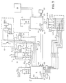
- Figure 3 is a schematic diagram of an embodiment of the present invention.
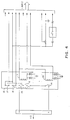
- Figure 4 is a detailed schematic diagram of the output control device of an embodiment of the present invention.
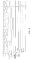
- Figure 5 is a pulse diagram of an exemplar of the operation of the light switch of an embodiment of the present invention.
- the ideal output control device consists of a primary part normally controlling current flow in the machine-stopping current loop, a provision for monitoring the health of the primary part, and a backup part which can control the current flow should the primary part be found to have failed. Additional constraints on the ideal device are that 1) the backup part be kept in like-new condition against the day that it must serve and that 2) the monitoring of the primary part not create a potential interference, mechanical or electrical, with the operation of the primary part.
- the output device of the present invention meets all of those conditions. Although it has more general applicability, for definitiveness the invention will be discussed in terms of its preferred embodiment.
- the output control device has a compound primary relay and a simple backup relay.
- the compound primary relay actually consists of two primary relays wired in series ⁇ and in series with the backup relay ⁇ and two dummy relays, which are not wired into the machine-stopping current loop. (The use of two primary relays is not key; a single one could be used, or more than two. The purpose in using more than one is to provide added redundancy, though with the safeguards of the present invention that is probably not necessary.)
- the two primary relays close upon the energizing of an associated primary solenoid or solenoid pair.
- the backup relay closes upon the energizing of an associated backup solenoid. During normal operation, it is only the primary solenoid which is de-energized when a light blockage occurs. The backup solenoid remains energized throughout the operating day, so that the backup relay flexes only upon power-up and power-down.
- Each of the two primary relays is mechanically coupled (ganged) with one of the dummy relays, in such a way that the state (open or closed) of each dummy relay is uniquely determined by the state of its ganged primary relay. Should the primary relay weld shut, the associated dummy relay will remain in the state associated with that primary relay being closed, regardless of the energizing of the primary solenoid(s). It can be seen that this mechanical ganging permits the state of each primary relay to be determined without need to make any electrical connections across that primary relay itself. For example, an ohmmeter attached across the contacts of a dummy relay could serve that function. There are a variety of ways in which the state of either of the dummy relays can be determined.
- the method set out in the PREFERRED EMBODIMENT consists of connecting one side of a dummy relay to a dc voltage terminal of the control circuit's power supply and the other side to ground through a large resistor.
- the state of the dummy can then be measured by noting the voltage drop across the large resistor. With the dummy relay open it will be zero; with the dummy relay closed, it will be some finite positive value (basically the voltage put out by the power supply at the terminal in question; all the drop will occur across that resistor).
- the voltage drop across the resistor ⁇ a bimodal value ⁇ is then observed by one of the microcontrollers.
- the microcontroller de-energizes the primary solenoid(s) and the backup solenoid. Furthermore, that microcontroller imposes a latching condition so that it is not easy to re-energize either solenoid. This helps ensure that the problem with the relay will be resolved before the guarded machine is run again.
- One compound relay which is available contains a normally open (n/o) pair which is appropriate for the primary relays. (It is important to use a n/o relay to ensure that the current loop will open upon failure of power to the solenoid.) It also contains a normally closed (n/c) pair which can serve as the matching dummy relays. When such a unit is used in this invention, a high monitor signal is commensurate with an energized primary solenoid and a low monitor signal with a de-energized primary solenoid.
- the backup relay contacts open only upon a failure or when the system is powered down; they do not cycle upon penetration of the light curtain, providing that the primary relays both perform properly. This is important, because it is the eventual welding (or other failure) of the primary relays which the backup is to provide security against. Welding occurs because of the pitting and softening of the contacts' metal surfaces due to arcing, which can be associated with opening and closing the contacts. Minimizing the switching activity of the backup relay avoids this and also lessens the metal fatigue of the contact armature and coil, which might otherwise result in sluggish relay response.
- the backup relay is cycled and checked during startup. Apart from this, it is only during failure of a primary relay that the backup is opened and upon that occurrence it is latched open.
- the light curtain switch of the present invention uses a split power supply in order to ensure dependable and rapid opening of the output control device upon receipt of an output control signal (or "timeout, latchout" signal).
- the power supply design was also selected with the minimization of electrical noise from the control system which, since it is highly tuned to pick up abnormal signals, might otherwise be tripped by such noise and produce excessive nuisance shutdowns.
- the AC line power feeding the AC power supply is filtered to minimize electrical "line noise" introduced into the system.
- the AC power is stepped down in voltage and passed through a full- wave rectifier so as to produce two DC voltage taps: 5 VDC and 6 VDC. These voltages are further regulated to eliminate fluctuations.
- the reason for proceeding in this fashion, splitting the final DC power is to separate the power for the primary relay solenoid from that for the rest of the circuit. In this way, noise caused by the energizing of the primary solenoid coil will not be introduced into the control circuit.
- overvoltages being applied to the control circuit and undervoltages being applied to the microcontrollers.
- this overvoltage protection circuit will activate, sending the voltage to ground.
- the overvoltage spike causes the momentary flow of current to ground, there will be a current spike drawn from the power supply; this will activate a circuit breaker and interrupt power. This approach prevents overvoltages from entering the control circuit itself, where it could easily damage the integrated circuit chips (ICs).
- ICs integrated circuit chips
- Undervoltage detectors are on the DC power line coming into each of the microcontrollers. They intrude and activate a program reset whenever the voltage on the line falls to 4.7 VDC. (The resetting of the microcontrollers will cause the relays in the output control device to open.)
- the purpose of the undervoltage protection is to prevent the microcontrollers from entering a "confused" state in which data becomes jumbled and switching points ambiguous, in a manner characteristic of binary logic circuits.
- the control circuit In response to a concern with spurious voltages, the control circuit is placed in a well-shielded box. This still leaves the large arrays of photodetectors and photosources directly exposed to the factory environment, with its ample supply of RF and lower-frequency EM waves. To guard against such interference the photosources and photodetectors are encased in thick grounded aluminum cases, and with all connecting cables well-shielded. To complete the electrical shielding of the sources and detectors, the glass windows leading to the sources and detectors are painted with an electrically-conductive material transparent to the infrared. The wire in the cable assembly which connects the aluminum cases to ground thus serves to electrically ground the window surfaces as well.
- the first type simply de-energizes the primary solenoid, and occurs during startup checks, during running checks, and when the light curtain is penetrated.
- the second type is sent when the control circuit has "concluded” that there is a malfunction somewhere in the system and it is supposed to de-energize the backup solenoid. When that second output control signal is sent, that part of the control circuit which energizes the solenoids is "latched” so that re-energizing cannot be accomplished in the normal way.
- the control system of the present invention is very sensitive to stimuli of both kinds, those indicating light curtain penetration and those indicating a malfunction. Given that sensitivity, it is important to provide some flexibility so that false positives associated with electrical transients are not acted upon. To avoid nuisance shutdowns based on an error or penetration indication lasting a millisecond or less and arising from a short-term electrical transient ("glitch"), the present invention provides for computer flexibility, for intelligent response to stimuli.
- the light curtain system of the present invention can engage in internal adjustment and self-calibration.
- One approach is to examine the height of the pulse generated at a photodetector by unblocked light from the photosource which is the mate to that detector. If there is an effective degradation of a source (which in addition to a reduced output by an LED, for example, can arise from factors which increase the attenuation along the optical path leading from the source to the detector), the control system will increase the current through the LED or in equivalent ways increase the optical output of whatever other photosource may be in use. In the alternative, should this not be adequate, the same result can be achieved by changing the threshold level at which the detector in question responds.
- a detector output pulse of 40 mV or lower may be indicative of blockage by an object of the minimum size for which the light curtain is rated if the level in the absence of any blockage is 60 mV. If for some reason the level in the absence of blockage is much higher, say, 300 mV, there is the danger that even with blockage by an object of the rated size the residual voltage pulse from the detector may exceed 40 mV.
- the present system examines the detector output level in the absence of blockage. In the case of excessive light, the fixed threshold level for inferred blockage is replaced by a level equal to 90% of the unblocked level.
- the SYSTEM Microcontroller sequentially activates the photosources so that only one is energized at a time.
- the SYSTEM Microcontroller also sequentially activates the photodetector array, ensuring that there is synchronization between the energized source and the activated detector. (Although the duration of activation of a particular detector may exceed that of its matching source, the sequencing is arranged so that no two detectors are activated at the same time and so that no detector will be activated while any source other than its matched source is activated.)
- the WATCHDOG Microcontroller is monitoring the program half-a-step ahead of the SYSTEM Microcontroller, checking to make sure that the proper sequential signals are being transmitted by the SYSTEM.
- a light filter in front of the detector permits only light in the correct wavelength range to penetrate to the operative part of the detector.
- a phase-sensitive detector further isolates the signal from the background light and noise.
- a further optical safeguard to eliminate extraneous light is the use of a polarizer/analyzer pair in front of the source and detector respectively. In this manner, the system eliminates optical cross-activation, and extraneous-light activation, permitting a greater sensitivity to be used in the signal verification.
- the light curtain system undoubtedly will be exposed to harsh treatment due to the environment in which it must be located and also because of the maintenance which it must undergo.
- it will be subject to being struck by metal workpieces being fed into the machine on which it is mounted and it will be splashed by numerous solvents and cleaners.
- all array and control enclosure components are made of metal and supplied with extensive sealing to resist moisture intrusion.
- the infrared transmitting array windows are made from impact-resistant plastic and are coated to prevent scratching from normal cleaning maintenance.
- the light curtain system of the present invention performs thousands of internal self-checks a second while also checking over the entire system outside the microcontrollers, all while the light curtain is performing its machine-guarding function.
- the checks performed by the new system can be categorized in general as follows: (1) Hardware checks (source/detector alignment and equipment mismatch tests); (2) Output control device integrity check; (3) Internal system code (software and hardware) verification checks; (4) Complete system integrity checks; (5) Data Transmission and Processing checks; (6) Computer Operating Properly (COP) checks; (7) Clock Monitor checks.
- This check ⁇ actually a sequence of checks ⁇ searches for mismatch of hardware, e.g., the use of a 16-pair light curtain array with a control box set to operate only an 8-pair array. They are performed during the set-up procedure with the relay in the de-energized state with power on. (In other words, the relay is "open" during this stage, preventing operation of the guarded machine.)
- the SYSTEM microcontroller reads the six-position dip switch in the control box to determine the number of source/detector pairs the control is set to operate. This number, p , is stored in the memory of the SYSTEM microcontroller.
- the WATCHDOG microcontroller polls the number of sources, s , in the photosource array as well as the number of detectors, d , in the photodetector array. The WATCHDOG microcontroller then checks whether s equals d and, if it does, the WATCHDOG microcontroller sends this number to the SYSTEM microcontroller while simultaneously eliciting the number p from the SYSTEM microcontroller. At this point, both microcontrollers have both numbers p and s and can independently check to see whether p equals s .
- each individual source in the photosource array line up with its matching individual detector in the photodetector array.
- the SYSTEM microcontroller handles this hardware check during the setup mode.
- the SYSTEM microcontroller transmits a plurality of labeled signals, in series, to the photosource array.
- the series is multiplexed such that each source in the array receives an individual signal.
- the resultant signals from the detectors in the photodetector array are then demultiplexed and a detector pulse series is transmitted to the SYSTEM microcontroller.
- the SYSTEM microcontroller evaluates the detector pulse series to determine whether the particular detector signal received matches the corresponding labeled signal from an aligned photosource. If a match is not made, the relays of the output control device are latched open and an appropriate error message is sent to the machine operator.
- This check is first performed as part of the startup test sequence, then after every actuation of the output control device during operation.
- the output control device being an electromechanical relay
- the purpose of the check is to ensure that the relay contacts are opening and closing properly; it is carried out and monitored by the WATCHDOG microcontroller which, after determining whether the contacts are operating properly, sends this information to the SYSTEM microcontroler.
- One embodiment of the present invention incorporates a compound primary relay with two sets of primary contacts, with a monitoring means on each so that the state of the relay contacts ⁇ open or closed ⁇ can be read by the control circuit.
- the monitor signal is bimodal, so that the WATCHDOG need only look for a "0" or a "1" signal to know the state of the relay. It knows the state the primary relay contacts should be in, and if it finds that they are in the opposite state, it will act to open a backup relay.
- the SYSTEM microcontroller monitors the WATCHDOG to verify that the check was performed. If the SYSTEM microcontroller finds that this check was not performed, it takes over and deactivates the relays.
- the circuit of the present invention contains external signal jacks into which the current loop can be connected. Other external connectors are provided to make available the output control signal, to be interfaced with those machines which can make use of it. Certain "intelligent" modalities in modern production machines can utilize such a signal to mark where in a complex production cycle an interruption occurred and in this way ensure that the work is picked up again at the proper stage once the blockage or other problem has been eliminated.
- the WATCHDOG gets a signal it is not expecting, it will reset its signal register to that number and also send a signal to its fault register. If the fault register gets up to a predetermined number during a certain period (such as 255 x 200 ⁇ sec), the WATCHDOG microcontroller will send a Control Output Signal to the control output device, thus interrupting the operation of the guarded machine. If that predetermined number is not reached during the specified period, WATCHDOG sets it fault register and the procedure commences again.
- a predetermined number such as 255 x 200 ⁇ sec
- the PRIMARY RELAY and BACKUP RELAY both will be opened within 20 milliseconds and the operator will be notified of the nature of the failure.
- These checks are for the purpose of detecting certain failures within the microcontrollers themselves, such as stuck code sequence, absence of code generation, microcontroller failure, and specific hardware faults.
- the WATCHDOG checks to see whether the SYSTEM microcontroller correctly responded to this simulated blockage, the correct response being to send a "timeout" signal to the primary relay. When this proper operation is detected by the WATCHDOG, it overrides the signal to the relay and allows uninterrupted machine operation.
- One of the strengths of this test is that it involves simulated blockage at the front end of the system, and thus enables examination of how the entire system responds.
- the SYSTEM microcontroller must detect this darkening and send a Control Output Signal. Simultaneously, the SYSTEM is to report the darkening to the WATCHDOG. Since the WATCHDOG, having generated the bogus signal, "knows" that the SYSTEM microcontroller is responding to a false blockage signal it in turn sends an overriding signal to the relay, ensuring that it does not open (i.e., that it does not initiate the stopping mechanism of the guarded machine). With currently available electronics it is straightforward to effect this test on a given source/detector pair once each large cycle.
- the source/detector pair checked on each large cycle is indexed by means of an indexing register within the WATCHDOG. For example, if pair #4 is indicated on the indexing register, then next cycle pair #5 is selected.
- One way for the test to be effected is for the WATCHDOG to send out a strobe signal which reduces or eliminates the current to all photosources. The timing is such that it is pair #5 which is activated at that point. Normally, the SYSTEM will send an interrupt ("timeout") signal to the output control device. If this occurs, and is noted by the WATCHDOG, the latter will send out a blocking (override) signal.
- the characteristic opening time is long compared with the speed of the microcontrollers and so the WATCHDOG has ample time to send the override signal, even after the initial interrupt signal has been applied to the relay solenoid by the SYSTEM.
- the WATCHDOG is always aware of the state of the SYSTEM. If it notes that there is real blockage occurring in the midst of the test, the WATCHDOG ceases the test, removing the false blockage. Just like the case where the frequency of data transmission from SYSTEM to WATCHDOG is monitored, the WATCHDOG intervention in this test also can be set to be “forgiving.” E.g., it might wait until the SYSTEM had failed a certain number of times to generate an interrupt signal in response to the false blockage before it applied its own interrupt signal to the output control device.
- Both the SYSTEM microcontroller and the WATCHDOG microcontroller have a built-in "computer operating properly” (COP) system to help protect against software failures.
- COP computer operating properly
- This COP system is enabled in both microcontrollers immediately at power-up. It is then active in detecting a software failure during startup and at any time after a successful startup. If any software failure occurs, the COP system "times out” and resets the corresponding microcontroller, thus de-energizing the primary relay.
- the COP check's efficacy depends on the clock of the larger system. If that clock fails, the COP check will not indicate any failure, either in the clock or in the software which it is designed to monitor. Thus a Clock Monitor is used as a backup for the COP system.
- the Clock Monitor is enabled in both the SYSTEM and WATCHDOG microcontrollers at powerup. If any of the microcontroller system clocks fail, then the Clock Monitor detects such a failure and forces the corresponding microcontroller to a reset state, thus de-energizing the primary relay.
- the Clock Monitor function is active in detecting the system clock failure during startup and any time after a successful startup.
- FIGURE 1 The general operation of the preferred embodiment of the present invention is illustrated in FIGURE 1 by light curtain system 101 , comprised of a LED photosource array 3 , a photodetector array 4 , a shielded control box 105 , an interconnecting photosource cable 106 and an interconnecting photodetector cable 107 .
- the purpose of said light curtain system 101 is to guard a certain area 107 in front of a hazard point such as is represented by an in-running nip point 108 .
- Said control box 105 houses a control circuit 21 constructed to activate a plurality of photosources 109 and a plurality of photodetectors 110 and to analyze light 111 originating at said plurality of photosources 109 and incident on said plurality of photodetectors 110 .
- said control circuit 21 determines that a blockage of said light 111 is occurring, it acts on a machine-stopping circuit 112 through a machine-stopping current loop 12 in order to prevent an opaque object 113 causing said blockage 111 from reaching a machine 200 comprising said hazard 108 as said machine 200 is in operation.
- the present Area Light Switch is in effect a switch provided to trip said machine-stopping circuit 112 if and when said area 107 is penetrated by said opaque object 113 . It does not incorporate said machine-stopping circuit 112 nor does it have any separate power over said hazard 108 .
- the novelty of this Area Light Switch is the reliability and speed with which it operates.
- the general layout of said control circuit 21 of the preferred embodiment of the present invention can be understood through reference to the schematic depicted in FIGURES 2 and 3.
- the heart of the invention comprises a programmed SYSTEM microcontroller 1 and a programmed WATCHDOG microcontroller 2 .
- the preferred embodiment uses a 68HC811E2 microcontroller as the foundation of said SYSTEM microcontroller 1 and a 68HC711E2 microcontroller as the foundation of said WATCHDOG microcontroller 2 .
- Said SYSTEM microcontroller 1 through its internal programming controls the scanning of said photosource array 3 and of said photodetector array 4 while also handling the analogue-to-digital conversion of the electrical output from said photodetectors 110 .
- Multiplexer means are used to first distribute a source pulse train 7 sequentially among said photosources 109 .
- Demultiplexer means are used to convert the output of said photodetector array 4 into a detector pulse series 8 .
- Said WATCHDOG microcontroller 2 performs diagnostic and self-check functions in conjunction with said SYSTEM microcontroller 1 , utilizing its own internal program.
- Said SYSTEM microcontroller 1 is triggered and otherwise regulated by system crystal 5
- WATCHDOG microcontroller 2 is similarly triggered and otherwise regulated by watchdog crystal 6 .
- Said system crystal 5 sets and controls a SYSTEM clock 9 within said SYSTEM microcontroller 1 and is completely independent from said watchdog crystal 6 , which sets and controls a WATCHDOG clock 10 within said WATCHDOG microcontroller 2 .
- said system crystal 5 and said watchdog crystal 6 both utilize 8-MHz SRMP49 crystals.
- said SYSTEM clock 9 and said WATCHDOG clock 10 are set to zero, so as to ensure synchronization of said SYSTEM microcontroller 1 with said WATCHDOG microcontroller 2 during subsequent operations.
- a start-up "self-check" mode is initialized by said SYSTEM microcontroller 1 and said WATCHDOG microcontroller 2 .
- Said self-check mode begins with the deactivation of an Output Control Device 11 .
- Said Output Control Device 11 can be understood through reference to FIGURE 3 in conjunction with FIGURE 2.
- FIGURE 3 shows said output control device 11 wired into said machine-stopping current loop 12 .
- Said output control device 11 includes a compound primary relay 13 and a backup relay 14 wired in series with one another and with the rest of said machine-stopping current loop 12 .
- FIGURE 4 depicts said compound primary relay 13 , which comprises a first relay 15 , a second relay 16 , a first dummy relay 17 and a second dummy relay 18 .
- Both said first relay 15 and said second relay 16 are normally "open.” To be closed they require the energizing of a primary relay solenoid 19 .
- Said first dummy relay 17 and said second dummy relay 18 are normally closed.
- Said first relay 15 is wired in series with said second relay 16 .
- Said first relay 15 is mechanically coupled to said first dummy relay 17 so that when said first relay 15 opens, said first dummy relay 17 is forced closed and when said first relay 15 closes, said first dummy relay 17 is forced open.
- An identical mechanical coupling exists between said second relay 16 and said second dummy relay 18 .
- said first dummy relay 17 opens only when said first relay 15 actually closes and vice versa. Should said first, relay 15 weld shut so that it remains closed even when said primary relay solenoid 19 is de-energized, said first dummy relay 17 will remain open.
- Said second relay 16 and said second dummy relay 18 operate in the same manner, although in a mutually exclusive way, as previously described.
- the remainder of said output control device comprises said backup relay 14 , which is controlled by a backup relay solenoid 20 .
- said compound primary relay 13 is wired into the rest of said control circuit 21 in two ways.
- said primary relay solenoid 19 is energized and de-energized by said control circuit 21 , and similarly for said backup relay solenoid 20 .
- said control circuit 21 is connected to said first dummy relay 17 and said second dummy relay 18 for monitoring purposes to be set out in more detail below.
- there is no electrical connection between said control circuit 21 and said first relay 15 , said second relay 16 , or said backup relay 14 all of which are wired in series in a circuit completely separate from said control circuit 21 , namely said machine-stopping current loop 12 .
- said machine-stopping current loop 12 must be completed through connection to a loop external to the present invention, a loop tied into a machine-stopping mechanism depending for its activation on the interruption in continuity of said machine-stopping current loop 12 , such as is provided by the opening of said first relay 15 , said second relay 16 , or said backup relay 14 .
- said primary relay solenoid 19 will be energized causing both said first relay 15 and said second relay 16 to be closed.
- said backup relay solenoid 20 will be energized, causing said backup relay 14 to be closed. This ensures continuity in that part of said current loop 12 and permits the operation of any machine properly interfaced with said current loop 12 .
- control output signal generated by said control circuit 21 consists of a simple de-energizing of said primary relay solenoid 19 , which results in the opening of said first relay 15 and said second relay 16 .
- said relay solenoid 20 continues to be energized. In this way fatigue of said backup relay 14 is minimized in comparison with that of said first relay 15 and said second relay 16 .
- said backup relay solenoid 20 is also de-energized, ensuring that all three relays in said current loop 12 are opened during this stage of operation.
- the purpose of said first dummy relay 17 and said second dummy relay 18 is to provide a means by which said control circuit 21 can determine whether or not said first relay 15 and said second relay 16 , respectively, are functioning properly.
- said first dummy relay 17 is in series with a resistance R m1 and that said second dummy relay 18 is in series with a resistance R m2 .
- a do voltage V is connected to one side of said first dummy relay 17 and to one side of said dummy relay 18 .
- the voltage drop across R m1 is monitored through a first monitor line 22 connected to said WATCHDOG microcontroller 2 and the voltage drop across R m2 is monitored through a second monitor line 23 connected to said WATCHDOG microcontroller 2 .
- said first monitor line 22 will sense a zero voltage and when said first dummy relay 17 is closed, said first monitor line 22 will sense a voltage of V .
- said second dummy relay 18 being open and closed, respectively. In this manner, a binary signal is generated apprising said WATCHDOG microcontroller 2 of the state (open or closed) of said first relay 15 and said second relay 16 .
- said WATCHDOG microcontroller 2 can determine when a "wrong" state occurs, i.e., a state inconsistent with the state of said primary relay solenoid 19 .
- said SYSTEM microcontroller 1 and/or said WATCHDOG microcontroller 2 discovers such an inconsistency, it de-energizes said backup relay solenoid 20 , as well as ensuring that said primary relay solenoid 19 is de-energized.
- it internally "latches” both said backup relay solenoid 20 and said primary relay solenoid 19 so that they cannot be re-energized until the problem with said compound primary relay 13 has been resolved.
- the monitoring method described here is only one of many such monitoring schemes when one is dealing with a system coupled mechanically but not electrically to relays of an output control device.
- the essence of the monitoring disclosed by the present invention is that it is done in such a way as to avoid any electrical connection to the machine-stopping sub-circuit.
- the backup part of the device is connected in such a way as to minimize its fatigue during normal operations.
- Said output control device 11 in the preferred embodiment may incorporate readily available components, using, for example, an "H-462 Safety Relay" for said compound primary relay 13 .
- a separate circuit power supply line 50 delivers power from a circuit supply source 51 to said control circuit 21
- an isolated output control power supply line 52 delivers power from a control supply source 53 to said primary relay solenoid 19 .
- noise resulting from the energization of said primary relay solenoid 19 will not affect said control circuit 21 .
- an over-voltage detection circuit 54 and under-voltage detectors 55 operate to minimize fluctuation effects.
- said over-voltage detection circuit 54 detects voltage spikes in said circuit power supply line 50 and directs voltage to ground. In this way, voltage surges are directed away from said control circuit 21 .
- said under-voltage detectors 55 detect voltage reductions and reset said SYSTEM microcontroller 1 and said WATCHDOG microcontroller 2 . Through this resetting said primary relay 13 and said backup relay 14 are deactivated.
- said photosource array 3 and said photodetector array 4 are isolated from ambient radio frequency and electromagnetic interference. This is achieved in the present invention through several techniques. First, said arrays 3 and 4 are made of aluminum. Next, window portions 115 of said photosources 109 and said photodetectors 110 are coated with an infrared-transparent conductive material. Further, shielded drain wires 116 and 117 conduct interferences from said photosource cable 106 and said photodetector cable 107 respectively.
- Additional protection of said photosources 109 and said photodetectors 110 involves gasket-sealing them with a NEMA #4-rated gasket, or equivalent.
- Connector pins 121 of said arrays 3 and 4 are preferably fabricated in one piece and O-ring sealed.
- An external protective covering 122 on both said photosource cable 106 and said photodetector cable 107 is made of a liquid-tight material.
- an error register and response capability is designed into the relationship between said SYSTEM microcontroller 1 , said WATCHDOG microcontroller 2 , and said output control device 11 .
- said WATCHDOG microcontroller 2 receives said source pulse train 7 from said SYSTEM microcontroller 1 as said SYSTEM microcontroller 1 transmit said source pulse train 7 to said photosource array 3 . If said WATCHDOG microcontroller 2 discovers a discrepancy in the signals from said plurality of detector pulses 81 when compared with the signals transmitted via said source pulse train 7 , it indexes a WATCHDOG fault register 560 .
- said WATCHDOG fault register 560 Should said WATCHDOG fault register 560 reach a preset threshold number, which for the preferred embodiment is 200 ⁇ sec x 255, it will send a timeout-latchout signal to both said primary relay 13 and said backup relay 14 . If said WATCHDOG fault register 560 does not reach the threshold number during the set time period, said WATCHDOG microcontroller 2 resets said fault register 560 to zero and the process begins again. In this way, random electrical transient spikes will not result in machinery shutdown caused by an overly sensitive evaluation process.
- a preset threshold number which for the preferred embodiment is 200 ⁇ sec x 255
- either the source signal to any one of said photosources 109 may be modified, or, the threshold level at which any one of said photodetectors 110 responds to the stimulus from its corresponding photosource may be changed in order to accommodate machine use variations.
- Such modifications are made at the level of said SYSTEM microcontroller 1 and said WATCHDOG microcontroller 2 , as described in the SUMMARY, and must be made without adjusting the gain on said photodetector array 4 .
- the next task of said SYSTEM microcontroller 1 and said WATCHDOG microcontroller 2 during startup mode is to check the hardware to make sure that said control circuit 21 matches said photosource array 3 and said photodetector array 4 .
- said photosource array 3 so as to activate a number of sources s which is anything up to the total number of sources on said photosource array 3 . It is possible to do the equivalent for said photodetector array 4 .
- said control circuit 21 can be set to control a wide-ranging number of source/detector pairs. Consequently, the internal checking program must start out verifying that these three numbers are identical.
- This verification begins when said SYSTEM microcontroller 1 elicits through the first six terminals of a SYSTEM Port E 29 data signals from a parallel six dip switch port 30 of said control circuit 21 a six-digit binary number indicative of the dip switch number p of source/detector pairs said control circuit 21 has been preset to operate. Said dip switch number p is then stored in a register of said SYSTEM microcontroller 1 . Next said WATCHDOG microcontroller 2 polls (through a WATCHDOG Port E 31 ) from said photosource array 3 and said photodetector array 4 the source number s and the detector number d .
- said WATCHDOG microcontroller compares said source number s and said detector number d and, it they are found to be equal, said WATCHDOG microcontroller 2 sends that number to said SYSTEM microcontroller 1 via one of the lines in SYSTEM Port A 32 and WATCHDOG Port A 33 and SYSTEM Port D 34 and WATCHDOG Port D 35 linking said SYSTEM microcontroller 1 and said SYSTEM microcontroller 2 .
- said WATCHDOG microcontroller 1 elicits from said SYSTEM microcontroller 2 said dip switch number p .
- both said SYSTEM microcontroller 2 and said WATCHDOG microcontroller 1 have said dip switch number p and said detector number d found to be equal to said source number s by said WATCHDOG microcontroller.
- Each microcontroller then makes an independent comparison of said dip switch number p and said detector number d (found to equal said source number s ). If both microcontrollers find the two numbers in the final comparison to equal one another, the hardware verification check is deemed satisfied and said control circuit 21 moves on to the next check.
- said WATCHDOG microcontroller 2 latches out said compound primary relay 13 and said backup relay 14 and sends an explanatory error message ("sensor number mismatch") to the operator via a liquid crystal display 26 , which in the preferred embodiment of the invention is a microcontroller 2040A Display Unit, and said SYSTEM microoontroler 1 is disabled.
- the next phase of the "self-check" is the alignment check, which as with the Hardware Verification Check is carried out with said primary relay 13 and said backup relay 14 both deactivated (open). Much of the technique used during the alignment check is also followed during subsequent operation of the light curtain.
- the purpose of the alignment check is to determine that light from each LED of said photosource array 3 illuminates the correct detector (its matching member) of said photodetector array 4 . Signals from said photodetector array 4 are transmitted in the form of voltage to a detector voltage-to-current converter 24 . This enables the signal from said photodetector array 4 to be transmitted over long cables to said control circuit 21 without reducing the signal-to-noise ratio by nearly the degree that a voltage signal would be degraded.
- said current signal is converted to a voltage signal by a current-to-voltage converter 25 and then conveyed to said SYSTEM microcontroller 1 for verification.
- the signal emerging from said photodetector array 4 comprises a plurality of detector pulses 81 corresponding to each of the individual detectors of said photodetector array 4 being illuminated in sequence. Said plurality of detector pulses 81 is demultiplexed into said pulse detector series 8 . It is the task of said SYSTEM microcontroller 1 in this alignment check to verify that said detector pulse series 8 comprises a series of equally spaced pulses, of particular period. If said SYSTEM microcontroller 1 verifies this, the alignment check is deemed complete and the next self-check is conducted. (If the alignment check is failed, said primary relay 13 and said backup relay 14 are latched out and an error message sent to the operator of the light curtain via said liquid crystal display 26 .
- Said SYSTEM microcontroller 1 and said WATCHDOG microcontroller 2 check said output control device 11 during the startup procedure and then after every actuation of said output control device 11 during operation.
- said output control device 11 is the combination of said compound primary relay 13 and said backup relay 14 and "actuation" consists of energizing said primary relay solenoid 19 with said back relay solenoid 20 already energized. This check is performed using the monitoring scheme set out above in the discussion of said output control device 11 . During startup, said output control device 11 must pass this check before the startup procedure can advance.
- said SYSTEM microcontroller 1 During normal operation said SYSTEM microcontroller 1 generates said source code 7 and transmits it over said source array cable 106 to said photosource array 3 containing a plurality of multiplexers 520 .
- the complex of said source code 7 can be best understood with reference to FIGURES 3 and 5, which relates to the preferred embodiment and assumes said plurality of multiplexers to be four in number comprising a first multiplexer 521 , a second multiplexer 522 , a third multiplexer 523 , and a fourth multiplexer 524 .
- Each of said plurality of multiplexers 520 controls sixteen of said plurality of photosources 109 .
- each of said plurality of photosources is connected to a 5-volt dc line 530 coming from said control circuit 21 . Only for those of said plurality of photosources 109 which are activated, however, does said 5-volt dc line 530 result in current flow and light production.
- Said source code 7 is transmitted to said photosource array 3 over said source array cable 106 , which has eight lines, broken into a first source group 511 of four and a second source group 512 of four.
- Said first source group 511 enables a parallel transmission of a four-digit binary number ranging repetitively from 0000 (0) to 1111 (15).
- Said second source group 512 carries an individual line to each of said plurality of multiplexers 520 . It is said second group 512 which determines which of said plurality of multiplexers 520 is activated. In the preferred embodiment, a "low" signal applied to one of said plurality of multiplexers 520 activates it.
- Said second source group 512 comprises a Strobe 1 line 513 , a Strobe 2 line 514 , a Strobe 3 515 , and a Strobe 4 line 516 , each of which runs to a different one of said plurality of multiplexers 520 .
- a first multiplexer 521 and no other of the four multiplexers in said plurality of multiplexers 520 is activated.
- Said first multiplexer 521 controls the activation of a first group of sixteen LEDs 525 in the preferred embodiment.
- the cycling of the code on said first group 525 then controls said first multiplexer 521 in such a way as to cause said first multiplexer 521 to activate in turn each of said first group of sixteen LEDs 525 . And similarly for the remainder of said plurality of multiplexers 520 .
- said second multiplexer 522 controls a second group of sixteen LEDs 526 , and so on.
- Said WATCHDOG microcontroller 2 also receives said source code 7 from said SYSTEM microcontroller 1 , and compares it, especially the signals on said first group 525 with a WATCHDOG signal register 540 .
- a SYSTEM signal register 550 which along with said WATCHDOG signal register 540 , is set to zero initially and then indexed by unity each cycle. Said SYSTEM signal register 550 determines the code number to be transmitted.
- said WATCHDOG microcontroller 2 if said WATCHDOG microcontroller 2 discovers a discrepancy between the four bit binary number received from said SYSTEM microcontroller 1 and said WATCHDOG signal register 540 , it indexes said WATCHDOG fault register 560 . Should said WATCHDOG fault register 540 reach the preset threshold number within 200 ⁇ sec x 255, it will send a timeout, latchout signal to both said primary relay 13 and said backup relay 14 . If said WATCHDOG fault register 560 does not reach the threshold number, said WATCHDOG microcontroller 2 resets said fault register and the process begins again.
- SYSTEM microcontroller 1 and said WATCHDOG microcontroller 2 data transmission and evaluation checks are performed. These checks verify the proper flow of information and processing of that information.
- a WATCHDOG timer 150 records time intervals of 200 microseconds at a 5000 Hz frequency. If, during startup, said WATCHDOG microcontroller 2 fails to receive predetermined signals from said SYSTEM microcontroller 1 , said WATCHDOG microcontroller 1 cancels the startup process and sends an error message to a machine operator via said display 26 . If predetermined signals are not received during operation, said WATCHDOG microcontroller 2 relays a message to said primary relay 13 and said backup relay 14 , within 20 milliseconds of detection, to open.
- said WATCHDOG microcontroller 2 In order to verify that said light curtain system 101 is operating as expected, said WATCHDOG microcontroller 2 periodically conducts a system check whereby it sends a simulated blockage signal 600 directly to one of said photosources 109 . Said SYSTEM microcontroller 1 is not notified of this simulation and proceeds to transmit a fault signal 601 to both said output control device 11 and said WATCHDOG microcontroller 2 upon evaluation of each of said plurality of detector pulses 81 from said pulse detector series 8 . Said WATCHDOG microcontroller 2 first verifies that the appropriate fault signal 601 has been transmitted by said SYSTEM microcontroller 1 and then transmits a fault override signal 602 directly to said output control device 11 .
Landscapes
- Engineering & Computer Science (AREA)
- General Engineering & Computer Science (AREA)
- General Physics & Mathematics (AREA)
- Physics & Mathematics (AREA)
- Computer Hardware Design (AREA)
- Theoretical Computer Science (AREA)
- Life Sciences & Earth Sciences (AREA)
- General Life Sciences & Earth Sciences (AREA)
- Mechanical Engineering (AREA)
- Geophysics (AREA)
- Quality & Reliability (AREA)
- Electronic Switches (AREA)
- Geophysics And Detection Of Objects (AREA)
- Safety Devices In Control Systems (AREA)
Applications Claiming Priority (3)
| Application Number | Priority Date | Filing Date | Title |
|---|---|---|---|
| US07/755,566 US5218196A (en) | 1991-09-05 | 1991-09-05 | Light curtain system with system and watchdog microcontrollers |
| US755566 | 1991-09-05 | ||
| EP92919457A EP0605496B1 (de) | 1991-09-05 | 1992-08-31 | Vorrichtung und Verfahren zur Funktionssicherstellung insbesondere einer Lichtschranke |
Related Parent Applications (1)
| Application Number | Title | Priority Date | Filing Date |
|---|---|---|---|
| EP92919457A Division EP0605496B1 (de) | 1991-09-05 | 1992-08-31 | Vorrichtung und Verfahren zur Funktionssicherstellung insbesondere einer Lichtschranke |
Publications (2)
| Publication Number | Publication Date |
|---|---|
| EP0819881A2 true EP0819881A2 (de) | 1998-01-21 |
| EP0819881A3 EP0819881A3 (de) | 2001-08-22 |
Family
ID=25039694
Family Applications (2)
| Application Number | Title | Priority Date | Filing Date |
|---|---|---|---|
| EP92919457A Expired - Lifetime EP0605496B1 (de) | 1991-09-05 | 1992-08-31 | Vorrichtung und Verfahren zur Funktionssicherstellung insbesondere einer Lichtschranke |
| EP97203118A Withdrawn EP0819881A3 (de) | 1991-09-05 | 1992-08-31 | Steuervorrichtung für Lichtgitter |
Family Applications Before (1)
| Application Number | Title | Priority Date | Filing Date |
|---|---|---|---|
| EP92919457A Expired - Lifetime EP0605496B1 (de) | 1991-09-05 | 1992-08-31 | Vorrichtung und Verfahren zur Funktionssicherstellung insbesondere einer Lichtschranke |
Country Status (5)
| Country | Link |
|---|---|
| US (2) | US5218196A (de) |
| EP (2) | EP0605496B1 (de) |
| AU (1) | AU2561392A (de) |
| DE (1) | DE69225487T2 (de) |
| WO (1) | WO1993005412A1 (de) |
Cited By (6)
| Publication number | Priority date | Publication date | Assignee | Title |
|---|---|---|---|---|
| FR2788713A1 (fr) * | 1999-01-22 | 2000-07-28 | Robot Coupe Sa | Machine a trancher |
| EP1484577A1 (de) * | 2003-06-05 | 2004-12-08 | HILTI Aktiengesellschaft | Detektor zur Bestimmung der Position eines Laserstrahls |
| DE102005027230B4 (de) * | 2005-06-13 | 2008-06-05 | Sick Ag | Optoelektronischer Sensor und Verfahren zum Betrieb desselben |
| EP1933174A2 (de) | 2006-12-15 | 2008-06-18 | Leuze lumiflex GmbH + Co. KG | Lichtgitter |
| WO2011022845A1 (de) * | 2009-08-25 | 2011-03-03 | Hansruedi Walti-Herter | Anordnung zur photoelektrischen ermittlung der schusslage bei einem schiessziel |
| EP2490045A1 (de) * | 2011-02-21 | 2012-08-22 | Sick AG | Optoelektronischer Sensor und Verfahren zur Erfassung von Objekten |
Families Citing this family (77)
| Publication number | Priority date | Publication date | Assignee | Title |
|---|---|---|---|---|
| WO1993023772A1 (fr) * | 1992-05-15 | 1993-11-25 | The Nippon Signal Co., Ltd. | Circuit a balayage a surete intrinseque et capteur du type a faisceaux a axes optique multiples |
| US5408089A (en) * | 1993-09-02 | 1995-04-18 | White Storage & Retrieval Systems, Inc. | Object detection system with a plurality of detectors for moveable storage unit systems and work areas having exits |
| US5640006A (en) * | 1993-10-12 | 1997-06-17 | The Nippon Signal Co., Ltd. | Control circuit for a fail-safe multi-axis light beam type sensor |
| DE4334675A1 (de) * | 1993-10-12 | 1995-04-13 | Josef Femboeck | Vorrichtung zur Überwachung von Raumbereichen |
| US5553237A (en) * | 1994-12-13 | 1996-09-03 | Base Ten Systems, Inc. | Safety critical monitoring of microprocessor controlled embedded systems |
| DE69630182T2 (de) * | 1995-03-31 | 2004-05-27 | The Nippon Signal Co., Ltd. | Steuerschaltung eines tauchankerrelais |
| US5726920A (en) * | 1995-09-29 | 1998-03-10 | Advanced Micro Devices, Inc. | Watchdog system having data differentiating means for use in monitoring of semiconductor wafer testing line |
| US5880954A (en) * | 1995-12-04 | 1999-03-09 | Thomson; Robert | Continous real time safety-related control system |
| US5805451A (en) * | 1996-04-12 | 1998-09-08 | Stark Manufacturing, Inc. | Item selection and item loading error proofing apparatus |
| DE19624140A1 (de) * | 1996-06-17 | 1997-12-18 | Philips Patentverwaltung | System zum Übertragen von Daten |
| DE19715013B4 (de) * | 1997-04-11 | 2008-04-10 | Schneider Electric Gmbh | Schaltung zum Start einer Maschine und Verfahren zur Steuerung eines Starts einer Maschine |
| DE19715098B4 (de) * | 1997-04-11 | 2004-12-23 | Schneider Electric Gmbh | Überwachungsschaltung |
| KR100563456B1 (ko) * | 1997-04-14 | 2006-05-25 | 아시스트 신꼬, 인코포레이티드 | 무인반송대차 및 그 장치 |
| AU6818998A (en) * | 1997-04-23 | 1998-11-13 | Sick Ag | Machine |
| US6472877B1 (en) | 1997-06-25 | 2002-10-29 | Chevron U.S.A., Inc. | Method and apparatus for measuring the opening time of a medium voltage air circuit breaker |
| IT1295901B1 (it) * | 1997-10-31 | 1999-05-28 | Ottorino Barbuti | Barriera immateriale optoelettronica a regolazione automatica della soglia di scatto |
| DE19805722B4 (de) * | 1998-02-12 | 2007-02-08 | Sick Ag | Verfahren und Vorrichtung zur Überwachung von elektrischen Leitungen |
| US6384402B1 (en) | 1998-04-29 | 2002-05-07 | Automated Merchandising Systems | Optical vend-sensing system for control of vending machine |
| FR2778749B1 (fr) * | 1998-05-15 | 2000-07-28 | Jay Electronique Sa | Barriere optique formee d'elements emetteurs/recepteurs regroupes en mobiles |
| US6166371A (en) * | 1999-04-30 | 2000-12-26 | Beckman Coulter, Inc. | Diffuse reflective light curtain system |
| US6439830B2 (en) * | 1999-12-08 | 2002-08-27 | Total Mailroom Support, Inc. | Opening guard mechanism for printed product stacking device |
| US7843197B2 (en) | 2004-06-15 | 2010-11-30 | Pass & Seymour, Inc. | Protective device with end-of-life indication before power denial |
| DE20006578U1 (de) | 2000-04-10 | 2000-07-20 | Sick AG, 79183 Waldkirch | Stoppzeiterfassungssystem |
| US6732014B2 (en) * | 2001-02-27 | 2004-05-04 | Crane Co. | System for accomplishing product detection |
| US7286901B2 (en) | 2001-02-27 | 2007-10-23 | Crane Co. | Method and system for accomplishing product detection |
| US8548625B2 (en) * | 2001-08-23 | 2013-10-01 | Crane Merchandising Systems, Inc. | Optical vend sensing system for product delivery detection |
| US6683432B2 (en) * | 2001-09-12 | 2004-01-27 | Eigenpoint Company | Safety circuit with automatic recovery |
| DE10151416C1 (de) * | 2001-10-18 | 2003-04-10 | Siemens Ag | Multiplexerschaltung |
| DE10155583B4 (de) * | 2001-11-13 | 2004-09-30 | Leuze Lumiflex Gmbh + Co. Kg | Schaltungsanordnung |
| DE10155582B4 (de) * | 2001-11-13 | 2004-09-30 | Leuze Lumiflex Gmbh + Co. Kg | Schaltungsanordnung |
| US6979813B2 (en) * | 2001-11-21 | 2005-12-27 | Avril John G | Safety-shutoff device for a manually fed processing machine |
| DE50213497D1 (de) * | 2001-12-04 | 2009-06-10 | Sultex Ag | Einrichtung an einer Webmaschine zum Schutz von Personen |
| DE10213754A1 (de) * | 2002-03-18 | 2003-12-04 | Sick Ag | Sensor-Maschinen-Interface und Verfahren zu dessen Betrieb |
| DE20216757U1 (de) * | 2002-10-30 | 2003-01-09 | Sick AG, 79183 Waldkirch | Optische Überwachungsvorrichtung |
| US6914527B2 (en) * | 2003-04-29 | 2005-07-05 | Jui-Hung Hsu | Infrared detector |
| DE10322385B3 (de) * | 2003-05-17 | 2004-11-11 | Moeller Gmbh | Verfahren und Schaltungsanordnung zur Funktionsüberwachung eines elektronisch- mechanischen Positionsschalters |
| DE10323324B4 (de) * | 2003-05-23 | 2006-09-14 | Leuze Lumiflex Gmbh + Co. Kg | Optischer Sensor |
| JP4212970B2 (ja) * | 2003-06-30 | 2009-01-21 | 株式会社キーエンス | 安全リレーシステム |
| US7751160B1 (en) | 2004-07-28 | 2010-07-06 | Pass & Seymour, Inc. | Protective device with separate end-of-life trip mechanism |
| US7565222B2 (en) * | 2004-01-15 | 2009-07-21 | Fawn Engineering Corporation | Economical optical system to provide reasonable assurance of completed vend or vendible items from vending machines |
| US7327275B2 (en) * | 2004-02-02 | 2008-02-05 | Gecko Alliance Group Inc. | Bathing system controller having abnormal operational condition identification capabilities |
| DE102004020997A1 (de) * | 2004-04-19 | 2005-11-03 | Pilz Gmbh & Co. Kg | Sicherheitsschalteinrichtung für eine Sicherheitsschaltung |
| US7446302B2 (en) * | 2004-07-09 | 2008-11-04 | Automated Merchandising Systems, Inc. | Optical vend-sensing system for control of vending machine |
| GB2419297B (en) * | 2004-10-23 | 2009-06-03 | Michael Berner | Safety assembly |
| WO2006071925A1 (en) * | 2004-12-28 | 2006-07-06 | General Binding Corporation | Fiber optic safety and dynamic braking arrangement |
| US7805209B2 (en) * | 2005-03-01 | 2010-09-28 | Heidelberger Druckmaschinen Ag | Light barrier having separate output signals |
| US20060235655A1 (en) * | 2005-04-18 | 2006-10-19 | Qing Richard X | Method for monitoring function execution |
| DE102005028559B4 (de) * | 2005-06-21 | 2013-01-03 | E. Dold & Söhne KG | Verfahren und Vorrichtung zur Drehzahlüberwachung eines Elektromotors |
| US7343062B1 (en) * | 2006-01-17 | 2008-03-11 | Rockwell Automation Technologies, Inc. | Safety light curtain with MEMS |
| US7449634B1 (en) | 2006-05-24 | 2008-11-11 | Taymac Corporation | Electrical device cover |
| US7783078B2 (en) * | 2006-12-18 | 2010-08-24 | Fujitsu Transaction Solutions Inc. | Tunable object detection |
| US7918374B2 (en) * | 2007-01-29 | 2011-04-05 | Halex/Scott Fetzer Company | Portable fastener driving device |
| GB0708499D0 (en) | 2007-05-02 | 2007-06-06 | Renishaw Plc | Tool setting or analysis device |
| US20080295030A1 (en) * | 2007-05-22 | 2008-11-27 | Honeywell International Inc. | User interface for special purpose controller |
| DE102007031430B4 (de) * | 2007-07-05 | 2016-12-01 | Sick Ag | Verfahren zum Betrieb eines Lichtgitters und Lichtgitter |
| WO2009052214A2 (en) * | 2007-10-15 | 2009-04-23 | Complete Genomics, Inc. | Sequence analysis using decorated nucleic acids |
| DE202008012472U1 (de) | 2008-09-19 | 2010-02-11 | Sick Ag | Optoelektronischer Sensor |
| US20100157502A1 (en) * | 2008-12-18 | 2010-06-24 | Caterpillar Inc. | System for decoupling a power source from a load |
| DE202009001204U1 (de) * | 2009-02-03 | 2010-06-24 | Sick Ag | Schaltungsanordnung mit zeitlich abgestimmten Abläufen |
| DK2228895T3 (da) * | 2009-03-09 | 2013-04-08 | Sma Solar Technology Ag | Vekselretter med netværksgrænseflade |
| US7880888B2 (en) * | 2009-03-17 | 2011-02-01 | Rockwell Automation Technologies, Inc. | Photoelectric sensor for sensing a target |
| US8446247B2 (en) * | 2009-10-21 | 2013-05-21 | J&L Group International, Llc | Safety system |
| US9363867B2 (en) * | 2011-06-21 | 2016-06-07 | Enlighted, Inc. | Intelligent and emergency light control |
| US8895925B2 (en) * | 2012-02-24 | 2014-11-25 | Raytheon Company | Electromagnetic interference protection structure |
| US9496955B2 (en) | 2013-09-19 | 2016-11-15 | eocys, LLC | Devices and methods to produce and receive an encoded light signature |
| US11219335B2 (en) * | 2016-07-11 | 2022-01-11 | Koninklijke Philips N.V. | Feed chute for a food processor |
| US10725445B2 (en) * | 2016-11-11 | 2020-07-28 | Safe Tek, LLC | Systems, methods, and articles of manufacture for operation of an industrial machine |
| EP3399352B1 (de) * | 2017-05-05 | 2023-07-05 | Leuze electronic GmbH + Co. KG | Lichtschrankenanordnung |
| DE102017119275B4 (de) * | 2017-08-23 | 2019-07-25 | Sick Ag | Lichtvorhang |
| DE102019109121B4 (de) * | 2019-04-08 | 2023-07-06 | Fritsch Bakery Technologies GmbH & Co. KG | Vorrichtung zur Formung eines Teigbands |
| DE202019104105U1 (de) * | 2019-07-25 | 2020-10-28 | Leuze Electronic Gmbh + Co. Kg | Lichtschrankenanordnung |
| US11855610B1 (en) * | 2020-08-27 | 2023-12-26 | Rockwell Collins, Inc. | Broadband data multiplexer |
| DE102021103952A1 (de) | 2021-02-19 | 2022-08-25 | Sick Ag | Optoelektronische Sicherheitsvorrichtung |
| DE202021100816U1 (de) | 2021-02-19 | 2022-05-25 | Sick Ag | Optoelektronische Sicherheitsvorrichtung |
| EP4092449B1 (de) * | 2021-05-20 | 2023-07-05 | Leuze electronic GmbH + Co. KG | Lichtschrankenanordnung und verfahren zur erfassung von objekten in einem überwachungsbereich |
| US20230064811A1 (en) * | 2021-08-11 | 2023-03-02 | Eric Graham | XD Relay With Manual Override Knob |
| CN113900424B (zh) * | 2021-09-22 | 2024-06-18 | 北京航天巨恒系统集成技术有限公司 | 一种故障定位方法、装置、电子设备及相关系统 |
Citations (7)
| Publication number | Priority date | Publication date | Assignee | Title |
|---|---|---|---|---|
| US249074A (en) | 1881-11-01 | miller | ||
| US3774039A (en) | 1973-03-05 | 1973-11-20 | Scient Techn Inc | Photoelectric apparatus for detecting light reflected from an object |
| US3805061A (en) | 1973-04-23 | 1974-04-16 | Tyco Laboratories Inc | Object detecting apparatus |
| US4266124A (en) | 1979-08-10 | 1981-05-05 | Data Instruments, Inc. | Photoelectric object detector system |
| US4309696A (en) | 1978-06-26 | 1982-01-05 | Kabushiki Kaisha Komatsu Seisakusho | Trouble detecting unit in an optical security device |
| US4650990A (en) | 1984-08-16 | 1987-03-17 | Joensson Nils | Processor-controlled light screen wherein light beam carries coded signals |
| US4749853A (en) | 1986-01-20 | 1988-06-07 | Ag Fur Industrielle Elektronik Agie Losone Bi Locarno | Light barrier having multiplexer for actuating transceiver pairs and multiple channel operation |
Family Cites Families (19)
| Publication number | Priority date | Publication date | Assignee | Title |
|---|---|---|---|---|
| US3886413A (en) * | 1973-01-29 | 1975-05-27 | Xenex Corp | Presence sensing and self-checking control system |
| US3970846A (en) * | 1973-10-29 | 1976-07-20 | Xenex Corporation | Presence detecting system with self-checking |
| US4249074A (en) * | 1978-06-06 | 1981-02-03 | Xenex Corporation | Intrusion detector for press brake |
| US4284074A (en) * | 1978-07-26 | 1981-08-18 | Shaw Jr Seth T | IUD Arrangement |
| US4217534A (en) * | 1978-11-20 | 1980-08-12 | Loren Cole | Vehicle battery polarity indicator |
| US4520262A (en) * | 1979-09-10 | 1985-05-28 | Kenneth Ambler | Photoelectric safety screen with stray source detection |
| US4317604A (en) * | 1980-05-05 | 1982-03-02 | Merrill Krakauer | All-purpose merchandiser |
| CA1179752A (en) * | 1982-03-09 | 1984-12-18 | Gunter P. Grewe | Flame scanning circuit |
| FR2584557B1 (fr) * | 1985-07-02 | 1989-07-28 | Smh Alcatel | Systeme de telecontrole pour machines a affranchir |
| US4809217A (en) * | 1985-10-31 | 1989-02-28 | Allen-Bradley Company, Inc. | Remote I/O port for transfer of I/O data in a programmable controller |
| US4818866A (en) * | 1986-01-13 | 1989-04-04 | Data Instruments, Inc. | Intrusion detection system for operating industrial machines with variable sensitivity |
| US4724505A (en) * | 1986-09-23 | 1988-02-09 | Abraham Gelbort | Relay combination |
| US4988983A (en) * | 1988-09-02 | 1991-01-29 | Carroll Touch, Incorporated | Touch entry system with ambient compensation and programmable amplification |
| US5000692A (en) * | 1988-09-14 | 1991-03-19 | Matsushita Electric Works, Ltd. | I/O relay interface module |
| US5136704A (en) * | 1989-06-28 | 1992-08-04 | Motorola, Inc. | Redundant microprocessor control system using locks and keys |
| US5015840B1 (en) * | 1990-01-09 | 1995-04-11 | Scient Technologies Inc | Self-checking light curtain system and method of operation. |
| US5140197A (en) * | 1990-08-13 | 1992-08-18 | Dallas Semiconductor Corporation | Filtered detection plus propagated timing window for stabilizing the switch from crystal to ring oscillator at power-down |
| US5111123A (en) * | 1990-11-16 | 1992-05-05 | Delco Electronics Corporation | Motor driver interface fault detection apparatus using initial turn-on and noise timers |
| US5149921A (en) * | 1991-07-10 | 1992-09-22 | Innovation Industries, Inc. | Self correcting infrared intrusion detection system |
-
1991
- 1991-09-05 US US07/755,566 patent/US5218196A/en not_active Expired - Lifetime
-
1992
- 1992-08-31 EP EP92919457A patent/EP0605496B1/de not_active Expired - Lifetime
- 1992-08-31 AU AU25613/92A patent/AU2561392A/en not_active Abandoned
- 1992-08-31 WO PCT/US1992/007368 patent/WO1993005412A1/en not_active Ceased
- 1992-08-31 EP EP97203118A patent/EP0819881A3/de not_active Withdrawn
- 1992-08-31 DE DE69225487T patent/DE69225487T2/de not_active Expired - Fee Related
-
1993
- 1993-06-07 US US08/073,096 patent/US5559664A/en not_active Expired - Lifetime
Patent Citations (7)
| Publication number | Priority date | Publication date | Assignee | Title |
|---|---|---|---|---|
| US249074A (en) | 1881-11-01 | miller | ||
| US3774039A (en) | 1973-03-05 | 1973-11-20 | Scient Techn Inc | Photoelectric apparatus for detecting light reflected from an object |
| US3805061A (en) | 1973-04-23 | 1974-04-16 | Tyco Laboratories Inc | Object detecting apparatus |
| US4309696A (en) | 1978-06-26 | 1982-01-05 | Kabushiki Kaisha Komatsu Seisakusho | Trouble detecting unit in an optical security device |
| US4266124A (en) | 1979-08-10 | 1981-05-05 | Data Instruments, Inc. | Photoelectric object detector system |
| US4650990A (en) | 1984-08-16 | 1987-03-17 | Joensson Nils | Processor-controlled light screen wherein light beam carries coded signals |
| US4749853A (en) | 1986-01-20 | 1988-06-07 | Ag Fur Industrielle Elektronik Agie Losone Bi Locarno | Light barrier having multiplexer for actuating transceiver pairs and multiple channel operation |
Cited By (9)
| Publication number | Priority date | Publication date | Assignee | Title |
|---|---|---|---|---|
| FR2788713A1 (fr) * | 1999-01-22 | 2000-07-28 | Robot Coupe Sa | Machine a trancher |
| EP1484577A1 (de) * | 2003-06-05 | 2004-12-08 | HILTI Aktiengesellschaft | Detektor zur Bestimmung der Position eines Laserstrahls |
| US7307738B2 (en) | 2003-06-05 | 2007-12-11 | Hilti Aktiengesellschaft | Beam catcher |
| DE102005027230B4 (de) * | 2005-06-13 | 2008-06-05 | Sick Ag | Optoelektronischer Sensor und Verfahren zum Betrieb desselben |
| EP1933174A2 (de) | 2006-12-15 | 2008-06-18 | Leuze lumiflex GmbH + Co. KG | Lichtgitter |
| EP1933174A3 (de) * | 2006-12-15 | 2013-05-08 | Leuze lumiflex GmbH + Co. KG | Lichtgitter |
| WO2011022845A1 (de) * | 2009-08-25 | 2011-03-03 | Hansruedi Walti-Herter | Anordnung zur photoelektrischen ermittlung der schusslage bei einem schiessziel |
| US8570499B2 (en) | 2009-08-25 | 2013-10-29 | Sius Ag | Method for electronically determining the shooting position on a shooting target |
| EP2490045A1 (de) * | 2011-02-21 | 2012-08-22 | Sick AG | Optoelektronischer Sensor und Verfahren zur Erfassung von Objekten |
Also Published As
| Publication number | Publication date |
|---|---|
| DE69225487D1 (de) | 1998-06-18 |
| EP0605496B1 (de) | 1998-05-13 |
| EP0605496A1 (de) | 1994-07-13 |
| US5559664A (en) | 1996-09-24 |
| DE69225487T2 (de) | 1999-03-25 |
| WO1993005412A1 (en) | 1993-03-18 |
| US5218196A (en) | 1993-06-08 |
| AU2561392A (en) | 1993-04-05 |
| EP0605496A4 (de) | 1995-03-22 |
| EP0819881A3 (de) | 2001-08-22 |
Similar Documents
| Publication | Publication Date | Title |
|---|---|---|
| EP0605496B1 (de) | Vorrichtung und Verfahren zur Funktionssicherstellung insbesondere einer Lichtschranke | |
| EP0865636B1 (de) | Kontinuierliches und sicherheitsorientiertes echtzeit-steuersystem | |
| WO1997021182A9 (en) | Continuous real time safety-related control system | |
| JP7199428B2 (ja) | 無線送電のシステムと方法 | |
| US4520262A (en) | Photoelectric safety screen with stray source detection | |
| US5584319A (en) | Electro-optical valve-status supervision switch circuit for fire protection | |
| Pagare et al. | Simulation and performance analysis of arc guard systems | |
| CZ261692A3 (en) | Method of detecting failures in a textile goods path | |
| US6778079B2 (en) | Input/output methodology for control reliable interconnection of safety light curtains and other machine safety controls | |
| US4664870A (en) | Testable voted logic power interface | |
| GB2176600A (en) | Fire hazard detection system | |
| CA1275462C (en) | Self-monitoring reflection light barrier | |
| US4627057A (en) | Method and arrangement for the functional testing of computers | |
| US20130215418A1 (en) | System to Detect Failed Pixels in a Sensor Array | |
| CN1828118B (zh) | 具有单独的输出信号的光电栅栏 | |
| DE4440281A1 (de) | Einrichtung zur optischen Erfassung von Störlichtbogenentladungen | |
| EP0035522B1 (de) | Sicherheitsmechanismus einer fertigungsmaschine | |
| KR101045644B1 (ko) | 적외선 감지 장치 및 그 방법 | |
| KR102062525B1 (ko) | 자체 시험 기능을 구비한 연기감지기 | |
| KR101464131B1 (ko) | 자가진단형 불꽃감지기 | |
| Whipple et al. | Radiation Monitoring System Upgrade for the NBSR | |
| EP4363871A1 (de) | Prüfung eines lichtbogenerkennungssystems | |
| KR101146083B1 (ko) | 자가진단 기능을 구비한 침입 감지 장치 및 방법 | |
| Manual | SLC4 Safety Light Curtain | |
| GB2159988A (en) | Safety device |
Legal Events
| Date | Code | Title | Description |
|---|---|---|---|
| PUAI | Public reference made under article 153(3) epc to a published international application that has entered the european phase |
Free format text: ORIGINAL CODE: 0009012 |
|
| AC | Divisional application: reference to earlier application |
Ref document number: 605496 Country of ref document: EP |
|
| AK | Designated contracting states |
Kind code of ref document: A2 Designated state(s): CH DE FR GB IT LI |
|
| PUAL | Search report despatched |
Free format text: ORIGINAL CODE: 0009013 |
|
| AK | Designated contracting states |
Kind code of ref document: A3 Designated state(s): CH DE FR GB IT LI |
|
| 17P | Request for examination filed |
Effective date: 20020218 |
|
| 17Q | First examination report despatched |
Effective date: 20050218 |
|
| STAA | Information on the status of an ep patent application or granted ep patent |
Free format text: STATUS: THE APPLICATION IS DEEMED TO BE WITHDRAWN |
|
| 18D | Application deemed to be withdrawn |
Effective date: 20050629 |