EP0819882A2 - Insert lumineux - Google Patents
Insert lumineux Download PDFInfo
- Publication number
- EP0819882A2 EP0819882A2 EP97111893A EP97111893A EP0819882A2 EP 0819882 A2 EP0819882 A2 EP 0819882A2 EP 97111893 A EP97111893 A EP 97111893A EP 97111893 A EP97111893 A EP 97111893A EP 0819882 A2 EP0819882 A2 EP 0819882A2
- Authority
- EP
- European Patent Office
- Prior art keywords
- insert according
- lighting insert
- base part
- lamp
- lighting
- Prior art date
- Legal status (The legal status is an assumption and is not a legal conclusion. Google has not performed a legal analysis and makes no representation as to the accuracy of the status listed.)
- Granted
Links
- 238000005286 illumination Methods 0.000 title description 2
- 229910000906 Bronze Inorganic materials 0.000 claims abstract description 3
- 239000010974 bronze Substances 0.000 claims abstract description 3
- KUNSUQLRTQLHQQ-UHFFFAOYSA-N copper tin Chemical compound [Cu].[Sn] KUNSUQLRTQLHQQ-UHFFFAOYSA-N 0.000 claims abstract description 3
- 239000000463 material Substances 0.000 claims abstract description 3
- 238000009434 installation Methods 0.000 claims description 13
- 238000007373 indentation Methods 0.000 claims description 10
- 238000004873 anchoring Methods 0.000 claims description 2
- 238000003466 welding Methods 0.000 description 2
- 238000004026 adhesive bonding Methods 0.000 description 1
- LYKJEJVAXSGWAJ-UHFFFAOYSA-N compactone Natural products CC1(C)CCCC2(C)C1CC(=O)C3(O)CC(C)(CCC23)C=C LYKJEJVAXSGWAJ-UHFFFAOYSA-N 0.000 description 1
- 239000011521 glass Substances 0.000 description 1
- 239000011810 insulating material Substances 0.000 description 1
- 238000004519 manufacturing process Methods 0.000 description 1
- 239000004033 plastic Substances 0.000 description 1
- 239000004417 polycarbonate Substances 0.000 description 1
- 229920000515 polycarbonate Polymers 0.000 description 1
Images

Classifications
-
- H—ELECTRICITY
- H01—ELECTRIC ELEMENTS
- H01H—ELECTRIC SWITCHES; RELAYS; SELECTORS; EMERGENCY PROTECTIVE DEVICES
- H01H9/00—Details of switching devices, not covered by groups H01H1/00 - H01H7/00
- H01H9/16—Indicators for switching condition, e.g. "on" or "off"
- H01H9/161—Indicators for switching condition, e.g. "on" or "off" comprising light emitting elements
-
- F—MECHANICAL ENGINEERING; LIGHTING; HEATING; WEAPONS; BLASTING
- F21—LIGHTING
- F21V—FUNCTIONAL FEATURES OR DETAILS OF LIGHTING DEVICES OR SYSTEMS THEREOF; STRUCTURAL COMBINATIONS OF LIGHTING DEVICES WITH OTHER ARTICLES, NOT OTHERWISE PROVIDED FOR
- F21V15/00—Protecting lighting devices from damage
- F21V15/01—Housings, e.g. material or assembling of housing parts
-
- F—MECHANICAL ENGINEERING; LIGHTING; HEATING; WEAPONS; BLASTING
- F21—LIGHTING
- F21V—FUNCTIONAL FEATURES OR DETAILS OF LIGHTING DEVICES OR SYSTEMS THEREOF; STRUCTURAL COMBINATIONS OF LIGHTING DEVICES WITH OTHER ARTICLES, NOT OTHERWISE PROVIDED FOR
- F21V19/00—Fastening of light sources or lamp holders
- F21V19/04—Fastening of light sources or lamp holders with provision for changing light source, e.g. turret
-
- F—MECHANICAL ENGINEERING; LIGHTING; HEATING; WEAPONS; BLASTING
- F21—LIGHTING
- F21W—INDEXING SCHEME ASSOCIATED WITH SUBCLASSES F21K, F21L, F21S and F21V, RELATING TO USES OR APPLICATIONS OF LIGHTING DEVICES OR SYSTEMS
- F21W2111/00—Use or application of lighting devices or systems for signalling, marking or indicating, not provided for in codes F21W2102/00 – F21W2107/00
-
- H—ELECTRICITY
- H01—ELECTRIC ELEMENTS
- H01H—ELECTRIC SWITCHES; RELAYS; SELECTORS; EMERGENCY PROTECTIVE DEVICES
- H01H11/00—Apparatus or processes specially adapted for the manufacture of electric switches
- H01H11/0006—Apparatus or processes specially adapted for the manufacture of electric switches for converting electric switches
Definitions
- the invention relates to a lighting insert for an installation device, in particular Switches or buttons with a front-mounted lamp, which Has lamp wires for electrical connection.
- lamps which Depending on the design, it can be inserted into the installation device from the rear are or can be mounted on the front. Variants are also known here are arranged centrally or decentrally.
- a front-mounted lighting insert of the type mentioned is known from DE 44 09 932 A1. It has a housing, which is approximately cylindrical shaped lamp takes up about a third of its length and with a provided axially parallel to the jacket of the lamp linearly extending pull tab is. This pull tab is used to remove the form-fitting with light Frictional connection used in a recess in the installation device intended for this purpose Lamp.
- the lamp wires for the electrical connection of the lamp are on a so-called contact part arranged axially parallel on diametrically opposite sides and work with in the installation device specially adapted to this lighting application Contacts together. This means that for other installation devices another lighting application is required, which is then used again is specially adapted, otherwise the required power supply to the lamp is not guaranteed.
- the lighting insert is formed by a mounting base, in which the lamp is arranged, the mounting base with two diagonal, contacts offset from each other by 90 ° are provided from the mounting base stick out to the side.
- the mounting base advantageously has a symmetrical to its central axis Cross-section, preferably an approximately square cross-section, on the one hand despite its small dimensions, it is easy to use and, on the other hand, it is thereby favors a space-saving design enables.
- the contacts are rod-shaped. They advantageously consist of spring material, preferably spring bronze.
- the protruding from the mounting base The ends of the contacts must each be angled by 90 ° and be tangential extend to the outside of the base. If necessary, they can also be used have at least one offset.
- the mounting base formed in two parts and each has a base part and a base part, which work together positively.
- the base part and the base part with each other pivotally connected For the purpose of improved handling in the manufacture of the lighting insert are the base part and the base part with each other pivotally connected. According to a further development, this is achieved that for the pivotable connection of the base part and the base part a hinge is provided which allows the base lower part and the base part from a closed position to an open position are pivotable to each other.
- the joint can advantageously be of at least be formed a film hinge.
- Another embodiment of the invention provides that the mounting base on his Parting plane has indentations for the contacts inserted therein and that if necessary, on the base part opposite the indentations Pressure cams are provided which engage in the indentations and one fix the inserted contact firmly.
- Lamp wires of the lamp with the contacts located in the mounting base connected, for example welded advantageously one of the lamp wires can have an interposed series resistor. So that's it allows the same lamps for different applications with different To use light intensities.
- Hybrid resistance can be combined directly with the lamp.
- An embodiment of the invention also provides that the upper base part a has a positively shaped recess for the lamp in which the relevant Lamp can be used. To prevent a change in position, one is used on the lower part of the base molded web-like rib, which in the closed position counteracts the lamp applied to the base of the base.
- the mounting base can have contacts on its circumference with locking cams and / or Deformations are provided, which for positive anchoring in the respective Serve installation device. These locking cams and / or indentations are preferred point symmetrical to the central axis of the mounting base on its circumference arranged.
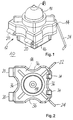
- a lighting insert 10 with an approximately square mounting base 12 is shown, which consists of a base upper part 14 and a base lower part 16 and of a lamp 18 inserted therein, consisting of a lamp made of glass Lamp body 19 is formed.
- the upper base part 14 and the lower base part 16 are made of an insulating material, preferably a sprayable plastic, for example polycarbonate. On their separable surfaces shown in FIG. 3 are the upper base part 14 and the Base part 16 is positively adapted to each other and by means of so-called an outside of integrally formed film hinges 20 pivotally connected.
- Contacts 22, 24 are provided for the electrical power supply to the lamp, which, as shown in FIG. 3, in groove-like indentations 26 provided for this purpose be inserted in wedge shape in the upper base part 14 and by appropriate, on Base base 16 molded projections 28 in the closed position of the lighting insert 10 are non-positively applied, that is, in the bottom of the groove of the wedge-shaped indentations.
- the contacts installed therein serve 22, 24 as a connection for lamp wires 30, 32 which lead out of the lamp body 19 are and each connected to the associated contacts, preferably are welded.
- the lamp wire 30 is in this case with an intermediate Series resistor 33 provided ..
- a web-like rib 36 is provided, which the lamp 18 from the Underside applied against the upper base part 14 and here sufficient There is space for the lamp wires 30, 32 and the series resistor 33.
- the mounting base is for improved handling of the lighting insert 10 12, that is to say the upper base part 14 and the lower base part 16 alike, provided on its outer sides with semi-cylindrical indentations 36. Further is the base part 16 is reset on its outer surface near the bottom over the entire circumference. This design allows the lighting insert 10 to be used accordingly preformed recesses in an associated, not shown here Installation device, easy to use or to replace refer to.
Landscapes
- Engineering & Computer Science (AREA)
- General Engineering & Computer Science (AREA)
- Fastening Of Light Sources Or Lamp Holders (AREA)
- Circuit Arrangement For Electric Light Sources In General (AREA)
- Luminescent Compositions (AREA)
- Non-Portable Lighting Devices Or Systems Thereof (AREA)
- Switch Cases, Indication, And Locking (AREA)
- Arrangement Of Elements, Cooling, Sealing, Or The Like Of Lighting Devices (AREA)
Applications Claiming Priority (2)
| Application Number | Priority Date | Filing Date | Title |
|---|---|---|---|
| DE19628755 | 1996-07-17 | ||
| DE19628755A DE19628755A1 (de) | 1996-07-17 | 1996-07-17 | Beleuchtungseinsatz |
Publications (3)
| Publication Number | Publication Date |
|---|---|
| EP0819882A2 true EP0819882A2 (fr) | 1998-01-21 |
| EP0819882A3 EP0819882A3 (fr) | 1999-12-15 |
| EP0819882B1 EP0819882B1 (fr) | 2005-11-16 |
Family
ID=7800030
Family Applications (1)
| Application Number | Title | Priority Date | Filing Date |
|---|---|---|---|
| EP97111893A Expired - Lifetime EP0819882B1 (fr) | 1996-07-17 | 1997-07-12 | Insert lumineux |
Country Status (3)
| Country | Link |
|---|---|
| EP (1) | EP0819882B1 (fr) |
| AT (1) | ATE310205T1 (fr) |
| DE (2) | DE19628755A1 (fr) |
Cited By (1)
| Publication number | Priority date | Publication date | Assignee | Title |
|---|---|---|---|---|
| WO2013018923A1 (fr) * | 2011-08-02 | 2013-02-07 | Yazaki Corporation | Éclairage d'intérieur de véhicule comprenant une partie de protection de source de lumière |
Families Citing this family (1)
| Publication number | Priority date | Publication date | Assignee | Title |
|---|---|---|---|---|
| DE10234024B4 (de) * | 2002-07-26 | 2008-09-11 | Abb Ag | Beleuchtungseinheit für ein elektrisches Installationsgerät |
Citations (1)
| Publication number | Priority date | Publication date | Assignee | Title |
|---|---|---|---|---|
| DE4409932A1 (de) | 1994-03-12 | 1995-09-14 | Abb Patent Gmbh | Beleuchtungseinsatz |
Family Cites Families (20)
| Publication number | Priority date | Publication date | Assignee | Title |
|---|---|---|---|---|
| US3197668A (en) * | 1960-04-11 | 1965-07-27 | John J Horan | Lamp with resilient contact terminals |
| US3403370A (en) * | 1965-10-15 | 1968-09-24 | Wagner Electric Corp | Mechanically based rear loading panel lamp |
| US3354454A (en) * | 1966-11-04 | 1967-11-21 | Amp Inc | One-piece signal housing |
| DE1298422B (de) * | 1967-11-30 | 1969-06-26 | Rudolf Zimmermann Ohg | Signalleuchte |
| US3859554A (en) * | 1968-05-13 | 1975-01-07 | Westinghouse Electric Corp | Electric lamp with integral plastic base member |
| DE6928329U (de) * | 1969-07-16 | 1969-12-18 | Siemens Ag | Signallampenanordnung, insbesondere fuer elektronische steuer- und regelanlagen |
| DE2131433C3 (de) * | 1971-06-24 | 1975-02-27 | Siemens Ag, 1000 Berlin Und 8000 Muenchen | Lichtsignalgeber |
| CH544912A (de) * | 1972-10-03 | 1973-11-30 | Cerberus Ag | Signalleuchte |
| US4152622A (en) * | 1977-06-24 | 1979-05-01 | Wagner Electric Corporation | Lamp-base assembly |
| DE8115978U1 (de) * | 1981-05-29 | 1981-10-01 | Albert Ackermann GmbH & Co, 5270 Gummersbach | Zimmersignalleuchte |
| DE3414162C1 (de) * | 1984-04-14 | 1985-06-05 | Hurst & Schröder GmbH, 5980 Werdohl | Elektrische Signalleuchte |
| AU7177191A (en) * | 1990-01-05 | 1991-07-24 | Joseph M. Ahroni | Improved chaser decorative light set and miniature light units |
| DE9103617U1 (de) * | 1991-03-23 | 1991-06-27 | Brökelmann, Jaeger & Busse GmbH & Co, 59755 Arnsberg | Lampenfassung, insbesondere für Halogenlampen |
| US5418698A (en) * | 1991-09-09 | 1995-05-23 | Wu; Jeng-Shyong | Decorative lighting string push-in type lighting socket unit |
| DE4317491A1 (de) * | 1993-05-26 | 1994-12-01 | Abb Patent Gmbh | Glimmlampe zum Einstecken |
| US5597329A (en) * | 1993-11-15 | 1997-01-28 | Daiichi Denso Buhin Co., Ltd. | Connector attachment component |
| DE4405760A1 (de) * | 1994-02-23 | 1995-08-24 | Marquardt Gmbh | Leuchtmittel sowie beleuchtbarer elektrischer Schalter |
| DE9410202U1 (de) * | 1994-06-23 | 1994-08-11 | Wong, Oscar, Taichung | Auf Schwingungen ansprechende Blinkleuchte |
| JP2677216B2 (ja) * | 1994-12-16 | 1997-11-17 | 株式会社押野電気製作所 | パネル・プリント基板用小形ランプソケット装置 |
| DE29508942U1 (de) * | 1995-05-30 | 1995-08-17 | Huang, Shun-Feng, Nei Hu Sub-Ward, Hsin-Chu | Weihnachtskerzenfassung |
-
1996
- 1996-07-17 DE DE19628755A patent/DE19628755A1/de not_active Withdrawn
-
1997
- 1997-07-12 AT AT97111893T patent/ATE310205T1/de not_active IP Right Cessation
- 1997-07-12 DE DE59712481T patent/DE59712481D1/de not_active Expired - Lifetime
- 1997-07-12 EP EP97111893A patent/EP0819882B1/fr not_active Expired - Lifetime
Patent Citations (1)
| Publication number | Priority date | Publication date | Assignee | Title |
|---|---|---|---|---|
| DE4409932A1 (de) | 1994-03-12 | 1995-09-14 | Abb Patent Gmbh | Beleuchtungseinsatz |
Cited By (2)
| Publication number | Priority date | Publication date | Assignee | Title |
|---|---|---|---|---|
| WO2013018923A1 (fr) * | 2011-08-02 | 2013-02-07 | Yazaki Corporation | Éclairage d'intérieur de véhicule comprenant une partie de protection de source de lumière |
| CN103732449A (zh) * | 2011-08-02 | 2014-04-16 | 矢崎总业株式会社 | 车室内照明灯 |
Also Published As
| Publication number | Publication date |
|---|---|
| DE19628755A1 (de) | 1998-01-22 |
| EP0819882A3 (fr) | 1999-12-15 |
| DE59712481D1 (de) | 2005-12-22 |
| EP0819882B1 (fr) | 2005-11-16 |
| ATE310205T1 (de) | 2005-12-15 |
Similar Documents
| Publication | Publication Date | Title |
|---|---|---|
| DE19530115C1 (de) | Lampenfassung für Leuchtstofflampen | |
| DE4020581C2 (fr) | ||
| DE4009279A1 (de) | Selbstruecksetzender tastschalter | |
| DE4129938A1 (de) | Druckknopfschalter | |
| DE2800936A1 (de) | Schalter, insbesondere fuer eine taschenlampe | |
| EP0753198B1 (fr) | Ensemble interrupteur pour interrupteur encastre a coiffe de commande montee flottante | |
| EP1322003B1 (fr) | Douille de lampe haute tension | |
| DE4018978C2 (de) | Schiebeschalter | |
| DE2137336A1 (de) | Wippschalter | |
| EP0819882A2 (fr) | Insert lumineux | |
| EP1168395A2 (fr) | Dispositif de commutation electrique | |
| EP1620926B1 (fr) | Ensemble d'etablissement de contact | |
| DE20212545U1 (de) | Schlüsselring | |
| DE10215020B3 (de) | Elektrischer Wippenschalter | |
| EP0378065B1 (fr) | Partie d'un boîtier avec un contact à fiches integré | |
| EP0475065A1 (fr) | Plafonnier de véhicule | |
| EP0626715B1 (fr) | Source lumineuse | |
| DE3306219C2 (de) | Schalter, insbesondere für Kraftfahrzeuge | |
| DE3126774C2 (de) | Schlüssel, insbesondere zur Betätigung von Kraftfahrzeugschlössern | |
| DE19723742A1 (de) | Befestigungsvorrichtung | |
| DE2206544C3 (de) | Leuchte | |
| DE9201236U1 (de) | Wipptastenanordnung mit einer Vierfachwippe für die Betätigung elektrischer Tippschalter | |
| DE8905767U1 (de) | Sockel für eine Kleinglühlampe | |
| DE4408366A1 (de) | Elektrischer Tastschalter | |
| DE2445292C2 (de) | Leuchte |
Legal Events
| Date | Code | Title | Description |
|---|---|---|---|
| PUAI | Public reference made under article 153(3) epc to a published international application that has entered the european phase |
Free format text: ORIGINAL CODE: 0009012 |
|
| AK | Designated contracting states |
Kind code of ref document: A2 Designated state(s): AT BE DE FI NL SE |
|
| PUAL | Search report despatched |
Free format text: ORIGINAL CODE: 0009013 |
|
| AK | Designated contracting states |
Kind code of ref document: A3 Designated state(s): AT BE CH DE DK ES FI FR GB GR IE IT LI LU MC NL PT SE |
|
| 17P | Request for examination filed |
Effective date: 20000413 |
|
| AKX | Designation fees paid |
Free format text: AT BE DE FI NL SE |
|
| RAP1 | Party data changed (applicant data changed or rights of an application transferred) |
Owner name: ABB PATENT GMBH |
|
| 17Q | First examination report despatched |
Effective date: 20040806 |
|
| GRAP | Despatch of communication of intention to grant a patent |
Free format text: ORIGINAL CODE: EPIDOSNIGR1 |
|
| GRAS | Grant fee paid |
Free format text: ORIGINAL CODE: EPIDOSNIGR3 |
|
| GRAA | (expected) grant |
Free format text: ORIGINAL CODE: 0009210 |
|
| AK | Designated contracting states |
Kind code of ref document: B1 Designated state(s): AT BE DE FI NL SE |
|
| PG25 | Lapsed in a contracting state [announced via postgrant information from national office to epo] |
Ref country code: NL Free format text: LAPSE BECAUSE OF FAILURE TO SUBMIT A TRANSLATION OF THE DESCRIPTION OR TO PAY THE FEE WITHIN THE PRESCRIBED TIME-LIMIT Effective date: 20051116 |
|
| RIC1 | Information provided on ipc code assigned before grant |
Ipc: 7F 21V 15/01 B Ipc: 7F 21S 8/00 A |
|
| REF | Corresponds to: |
Ref document number: 59712481 Country of ref document: DE Date of ref document: 20051222 Kind code of ref document: P |
|
| REG | Reference to a national code |
Ref country code: SE Ref legal event code: TRGR |
|
| NLV1 | Nl: lapsed or annulled due to failure to fulfill the requirements of art. 29p and 29m of the patents act | ||
| PG25 | Lapsed in a contracting state [announced via postgrant information from national office to epo] |
Ref country code: BE Free format text: LAPSE BECAUSE OF NON-PAYMENT OF DUE FEES Effective date: 20060731 |
|
| PLBE | No opposition filed within time limit |
Free format text: ORIGINAL CODE: 0009261 |
|
| STAA | Information on the status of an ep patent application or granted ep patent |
Free format text: STATUS: NO OPPOSITION FILED WITHIN TIME LIMIT |
|
| 26N | No opposition filed |
Effective date: 20060817 |
|
| PG25 | Lapsed in a contracting state [announced via postgrant information from national office to epo] |
Ref country code: AT Free format text: LAPSE BECAUSE OF NON-PAYMENT OF DUE FEES Effective date: 20060712 |
|
| BERE | Be: lapsed |
Owner name: *ABB PATENT G.M.B.H. Effective date: 20060731 |
|
| PGFP | Annual fee paid to national office [announced via postgrant information from national office to epo] |
Ref country code: FI Payment date: 20160713 Year of fee payment: 20 Ref country code: DE Payment date: 20160722 Year of fee payment: 20 |
|
| PGFP | Annual fee paid to national office [announced via postgrant information from national office to epo] |
Ref country code: SE Payment date: 20160720 Year of fee payment: 20 |
|
| REG | Reference to a national code |
Ref country code: DE Ref legal event code: R071 Ref document number: 59712481 Country of ref document: DE |