EP0819887A2 - Abgasverbrennung - Google Patents
Abgasverbrennung Download PDFInfo
- Publication number
- EP0819887A2 EP0819887A2 EP97304282A EP97304282A EP0819887A2 EP 0819887 A2 EP0819887 A2 EP 0819887A2 EP 97304282 A EP97304282 A EP 97304282A EP 97304282 A EP97304282 A EP 97304282A EP 0819887 A2 EP0819887 A2 EP 0819887A2
- Authority
- EP
- European Patent Office
- Prior art keywords
- combustion
- nozzle
- exhaust gas
- gas
- combustion nozzle
- Prior art date
- Legal status (The legal status is an assumption and is not a legal conclusion. Google has not performed a legal analysis and makes no representation as to the accuracy of the status listed.)
- Granted
Links
Images
Classifications
-
- F—MECHANICAL ENGINEERING; LIGHTING; HEATING; WEAPONS; BLASTING
- F23—COMBUSTION APPARATUS; COMBUSTION PROCESSES
- F23G—CREMATION FURNACES; CONSUMING WASTE PRODUCTS BY COMBUSTION
- F23G7/00—Incinerators or other apparatus for consuming industrial waste, e.g. chemicals
- F23G7/06—Incinerators or other apparatus for consuming industrial waste, e.g. chemicals of waste gases or noxious gases, e.g. exhaust gases
- F23G7/061—Incinerators or other apparatus for consuming industrial waste, e.g. chemicals of waste gases or noxious gases, e.g. exhaust gases with supplementary heating
- F23G7/065—Incinerators or other apparatus for consuming industrial waste, e.g. chemicals of waste gases or noxious gases, e.g. exhaust gases with supplementary heating using gaseous or liquid fuel
-
- H—ELECTRICITY
- H10—SEMICONDUCTOR DEVICES; ELECTRIC SOLID-STATE DEVICES NOT OTHERWISE PROVIDED FOR
- H10P—GENERIC PROCESSES OR APPARATUS FOR THE MANUFACTURE OR TREATMENT OF DEVICES COVERED BY CLASS H10
- H10P95/00—Generic processes or apparatus for manufacture or treatments not covered by the other groups of this subclass
-
- F—MECHANICAL ENGINEERING; LIGHTING; HEATING; WEAPONS; BLASTING
- F23—COMBUSTION APPARATUS; COMBUSTION PROCESSES
- F23G—CREMATION FURNACES; CONSUMING WASTE PRODUCTS BY COMBUSTION
- F23G2209/00—Specific waste
- F23G2209/14—Gaseous waste or fumes
- F23G2209/142—Halogen gases, e.g. silane
Definitions
- the present invention relates to a method for combusting an exhaust gas such as silane gas (which is discharged from a reaction furnace of a semi-conductor plant and the like) to form a harmless gas by oxidation, and to an apparatus for carrying out the method.
- an exhaust gas such as silane gas (which is discharged from a reaction furnace of a semi-conductor plant and the like) to form a harmless gas by oxidation
- Exhaust gas such as silane gas which is discharged from a reaction furnace of semiconductor plants and the like is highly hazardous. Specifically, silane gas is inflammable when brought into contact with air. In order to prevent this silane, or other exhaust gas,is conventionally discharged as harmless gas from the combustion chamber by supplying air to the combustion chamber to combust the exhaust gas as the exhaust gas is discharged from the tip of a burner nozzle provided in the combustion chamber.
- silica exists as microscopic powder, which clogs the narrow bore of the nozzle thereby causing defective combustion in the case where a conventional burner nozzle is used.
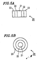
- FIGS. 5A and 5B show a nozzle 20 comprising three concentric tubes.
- the nozzle 20 includes a central silane gas introduction tube 21, a combustion gas ejection tube 22 surrounding the silane gas introduction tube 21, and an outermost mixture gas ejection tube 23 for ejecting a mixture gas including the combustion gas and air.
- Silane gas ejected from the silane gas introduction tube 21 is combusted by bringing the silane gas into contact with a flame which is generated by the mixture gas ejected from the mixture gas ejection tube 23.
- a combustion "curtain" of combustion gas ejected from the combustion gas ejection tube 22 is generated between the silane gas and the mixture gas.
- This combustion curtain prevents combustion of the silane gas in the vicinity of the tip of the silane gas introduction tube 21, and thus adhesion of silica to the tip of the nozzle is prevented.
- incomplete combustion may occur due to the small amount of air which is available for combustion; also, silane gas having a low concentration may not be removed.
- the invention therefore provides a method for combusting an exhaust gas using an exhaust gas combustion nozzle connected to a combustion chamber, the exhaust gas combustion nozzle including an exhaust gas nozzle; a first combustion nozzle being provided so as to surround the exhaust gas nozzle; a second combustion nozzle being provided so as to surround the first combustion nozzle; and an air supply nozzle being provided so as to surround the second combustion nozzle, wherein a first combustion flame ejected from the first combustion nozzle is a reducing flame, and a second combustion flame ejected from the second combustion nozzle is a subsequentially complete combustion flame.
- the method may include the steps of introducing an exhaust gas through the exhaust gas nozzle at a flow velocity of 1 to 8 metres/second; forming a reducing flame by ejecting a first mixture gas obtained by mixing a fuel gas with air at a mixing ratio (by weight) of fuel gas:air of 1:3 to 1:10 through the first combustion nozzle at a flow velocity of 3 to 5 metres/second; and forming a substantially complete combustion flame by ejecting a second mixture gas obtained by mixing a fuel gas with air at a mixing ratio by weight of fuel:air of 1:14 to 1:16 through the second combustion nozzle at a flow velocity of 5 to 7 metres/second.
- An oxygen deficient, or substoichiometric, combustion ratio may be formed by the first combustion flame from the first combustion nozzle so as to surround the exhaust gas introduced into the combustion chamber through the exhaust gas nozzle.
- the exhaust gas combustion nozzle in an apparatus for combusting an exhaust gas including an exhaust gas combustion nozzle connected to a combustion chamber, includes an exhaust gas nozzle provided at the centre of the exhaust gas combustion nozzle; an annular first combustion nozzle provided so as to surround the exhaust gas nozzle, the first combustion nozzle being capable of forming an oxygen deficient combustion region around the exhaust gas nozzle; a second combustion nozzle including a plurality of nozzles each having a small diameter arranged so as to surround the first combustion nozzle; and an air supply nozzle provided so as to surround the second combustion nozzle.
- an exhaust gas combustion nozzle has a four-layer structure. Due to a reducing flame curtain formed around an exhaust gas nozzle, combustion of a silane gas is suppressed in the vicinity if the exhaust gas nozzle.
- the silane gas is completely combusted at a location distant from the exhaust gas nozzle utilising the high temperature obtained from the reducing flame and combustion air supplied thereto.
- the silane gas can be completely combusted and removed regardless of the concentration of the silane gas.
- silica which is a combustion product if a silane gas
- the pilot gas is obtained by mixing fuel gas with a theoretical amount of air and is combusted to provide a complete combustion flame. Therefore, combustion of a pilot flame serving as an ignition source is stable throughout the operation. Thus, the apparatus can be operated safely.
- the invention prevents the reduction in combustion efficiency due to the clogging if the tip of the nozzle, and also enables gas having a low concentration to be satisfactorily processed.
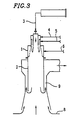
- Figure 3 is a schematic view of an apparatus for combining exhaust gas according to the present invention.
- the apparatus includes a substantially cylindrical combustion chamber 2 and an exhaust gas combustion nozzle 1 provided above the combustion chamber 2.
- An exhaust gas introduction tube 3, a first mixture gas introduction tube 4, a second mixture gas introduction tube 5, and an air introduction tube 6 are connected to the exhaust gas combustion nozzle 1.
- the exhaust gas combusted in the exhaust gas combustion nozzle 1 is discharged below the combustion chamber 2 and is mixed with air 8 drawn in from outside the nozzle.
- the mixture gas after being diluted, is sent outside the apparatus through a discharge path 9 by a blower (not shown). Products obtained by combustion, such as silica, are discharged through the discharge path 9 together with the air drawn in from outside.
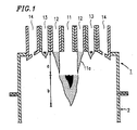
- the exhaust gas combustion nozzle 1 includes an exhaust gas nozzle 11 provided at the centre thereof, an annular first combustion nozzle 12 is provided outside the exhaust gas nozzle 11, a second combustion nozzle 13 is provided outside first combustion nozzle 12, and an air supply nozzle 14 is provided outside the second combustion nozzle 13.
- the exhaust gas nozzle 11 is cylindrical and is connected to the exhaust gas introduction tube 3.
- Exhaust gas such as silane gas is introduced into the exhaust gas combustion nozzle 1 downward from the exhaust gas nozzle 11.
- the flow velocity of the exhaust gas introduced from the exhaust gas nozzle 11 is preferably 1 to 8 metres/second.
- the first combustion nozzle 12 is connected to the mixture gas introduction tube 4, and a first mixture gas is ejected from the first combination nozzle 12.
- a first combustion flame is generated by the first mixture gas ejected from the first combustion nozzle 12.
- the first combustion flame is obtained by substoichiometric, oxygen deficient, combustion.
- the first mixture gas is preferably in the ratio (by weight) of combustion gas and air of 1:5 to 1:10 (1:15 in the case of complete, stoichiometric, combustion). By such oxygen deficient combination, a reduction combustion area is produced.
- the flow velocity of the first mixture gas is preferably 3 to 5 metres/second.
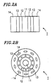
- the second combustion nozzle 13 is formed of a plurality of small-diameter nozzles arranged in a ring around the first combustion nozzle 12 at an appropriate interval.
- the small-diameter nozzles can be, for example, circular or elliptical.
- the second combustion nozzle 13 is connected to the second mixture gas introduction tube 5.
- a second combustion flame ejected from the second combustion nozzle 13 is a so-called pilot flame.
- the second mixture gas is preferably in the ratio (by weight) of combustion gas and air of 1:14 to 1:16, so that complete combustion is realised to maintain safe operation of the apparatus.
- the flow velocity of the second mixture gas is preferably 5 to 7 metre/second.
- the air supply nozzle 14 is formed as a plurality of nozzles arranged around the second combustion nozzle 13 at an appropriate interval.
- the nozzles can be, for example, circular, elliptical or rectangular.
- the air supply nozzle 14 is connected to the air introduction tube 6. A sufficient amount of air for combustion is supplied from the air supply nozzle 14 to realise complete combustion in the combustion range.
- letter a indicates the reduction combustion area
- letter b indicates the complete combustion area.
- Exhaust gas such as silane gas
- Exhaust gas is introduced from the exhaust gas nozzle 11 provided in the exhaust gas combustion nozzle 1 and the oxygen deficient first combustion flame is ejected from the first combustion nozzle 1.
- the pilot flame is constantly combusted in the second combustion nozzle 13. Even when a sufficient amount of air is supplied from the air supply nozzle 14, the exhaust gas is not substantially combusted at the tip of the first combustion nozzle 12 since the combustion flame ejected from the first combustion nozzle 12 is a reducing flame as shown in Figure 1.
- Silica which is obtained by combusting silane gas, does not clog the tip of the first and second combination nozzles 12 and 13.
- a stable flame is maintained for safe operation by mixing the combustion gas with a theoretical amount of air.
- a sufficient amount of air supplied from the air supply nozzle 14 allows the mixture gas and uncombusted gas from the first combustion nozzle 12 and the exhaust gas such as silane gas from the exhaust gas nozzle 11 to be completely combusted.
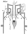
- an exhaust gas combustion nozzle 1 includes an exhaust gas nozzle 11, an annular first combustion nozzle 12, a second combustion nozzle 13, and an air supply nozzle 14.
- the tip of the exhaust gas nozzle 11 projects downward from the tip of the first and second combustion nozzles 12 and 13.
- the second combustion nozzle 13 is formed by an opening in a slanted surface 16.
- the air supply nozzle 14 is formed by an opening in a slanted surface 17.
- the air supply nozzle 14 is substantially level with or positioned slightly below a tip area 11a of the exhaust gas nozzle 11.
- silane gas having a concentration of about 0.5 to 100% was introduced into the exhaust gas combustion nozzle 1 from the exhaust gas nozzle 11 at a flow velocity of 1 to 8 metres/second.
- a first mixture gas (the mixture ratio by weight of the combination gas and air being about 1:10) was ejected from the first combustion nozzle 12 at a flow velocity of 3 metres/second
- a second mixture gas (the mixture ratio by weight of the combustion gas and air being about 1:15) was ejected from the second combustion nozzle 13 at a flow velocity of 7 metres/second
- a sufficient amount of air was ejected from the air supply nozzle 14.
- silane gas was combusted. After combusting the silane gas for 15 days, no adhesion of silica to any of the nozzles was observed.
- the temperature of the combustion chamber was 250 to 400°C.
Landscapes
- Engineering & Computer Science (AREA)
- Environmental & Geological Engineering (AREA)
- Mechanical Engineering (AREA)
- General Engineering & Computer Science (AREA)
- Incineration Of Waste (AREA)
- Gasification And Melting Of Waste (AREA)
- Combustion Of Fluid Fuel (AREA)
- Pre-Mixing And Non-Premixing Gas Burner (AREA)
Applications Claiming Priority (3)
| Application Number | Priority Date | Filing Date | Title |
|---|---|---|---|
| JP15859996 | 1996-06-19 | ||
| JP158599/96 | 1996-06-19 | ||
| JP15859996A JP3490843B2 (ja) | 1996-06-19 | 1996-06-19 | 排ガス燃焼方法及びその装置 |
Publications (3)
| Publication Number | Publication Date |
|---|---|
| EP0819887A2 true EP0819887A2 (de) | 1998-01-21 |
| EP0819887A3 EP0819887A3 (de) | 1998-10-28 |
| EP0819887B1 EP0819887B1 (de) | 2003-08-27 |
Family
ID=15675220
Family Applications (1)
| Application Number | Title | Priority Date | Filing Date |
|---|---|---|---|
| EP97304282A Expired - Lifetime EP0819887B1 (de) | 1996-06-19 | 1997-06-18 | Abgasverbrennung |
Country Status (5)
| Country | Link |
|---|---|
| EP (1) | EP0819887B1 (de) |
| JP (1) | JP3490843B2 (de) |
| KR (1) | KR100268815B1 (de) |
| DE (1) | DE69724358T2 (de) |
| TW (1) | TW335437B (de) |
Cited By (11)
| Publication number | Priority date | Publication date | Assignee | Title |
|---|---|---|---|---|
| WO2001033141A1 (en) * | 1999-11-02 | 2001-05-10 | Ebara Corporation | Combustor for exhaust gas treatment |
| EP1291069A1 (de) * | 2001-08-30 | 2003-03-12 | DAS-DÜNNSCHICHT ANLAGEN SYSTEME GmbH DRESDEN | Verfahren und Einrichtung zur Reinigung insbesondere von fluorhaltigen Abgasen in einem Brenner mit räumlicher Trennung der Einspeisung von Gasen |
| WO2003085321A1 (de) * | 2002-04-11 | 2003-10-16 | DAS-Dünnschicht Anlagen Systeme GmbH Dresden | Einrichtung zur reinigung von abgasen mit fluorhaltigen verbindungen in einem verbrennungsreaktor mit niedriger stickoxidemission |
| WO2005026616A1 (de) * | 2003-09-12 | 2005-03-24 | Centrotherm Elektrische Anlagen Gmbh + Co. Kg | Verfahren und vorrichtung für die thermische abgasreinigung |
| WO2006117531A1 (en) * | 2005-05-05 | 2006-11-09 | Edwards Limited | Gas combustion apparatus |
| WO2006123092A1 (en) * | 2005-05-16 | 2006-11-23 | Edwards Limited | Gas combustion apparatus |
| EP1312860A4 (de) * | 2000-08-22 | 2007-02-28 | Ebara Corp | Verfahren und vorrichtung zur behandlung von verbrennungsabgasen |
| WO2008001095A1 (en) * | 2006-06-30 | 2008-01-03 | Edwards Limited | Gas combustion apparatus |
| EP1605203A3 (de) * | 2004-06-07 | 2008-04-16 | Air Products And Chemicals, Inc. | Brenner und Verfahren zur Verbrennung eines zur Bildung fester Produkte fähigen Gases |
| US7462333B2 (en) | 2002-04-11 | 2008-12-09 | Das-Dunnschicht Anlagen Systeme Gmbh Dresden | Device for the purification of exhaust gases consisting of fluorine-containing compounds in a combustion reactor |
| CN102230631A (zh) * | 2011-06-03 | 2011-11-02 | 王兴文 | 一种废气焚烧热风炉烧嘴部的烧嘴砖 |
Families Citing this family (10)
| Publication number | Priority date | Publication date | Assignee | Title |
|---|---|---|---|---|
| DE102005040576B4 (de) * | 2005-08-26 | 2007-08-16 | Centrotherm Clean Solutions Gmbh & Co. Kg | Luftbrenner zur Verbrennung von Abgasen aus Prozessen zur Behandlung von Halbleitern |
| KR100623369B1 (ko) | 2005-09-05 | 2006-09-12 | 크린시스템스코리아(주) | 반도체 제조장비용 배기가스 처리장치의 버너 |
| DE102006034885A1 (de) | 2006-07-25 | 2008-08-07 | Daimlerchrysler Ag | Wasserstoff- und Energiegewinnung durch thermische Umsetzung von Silanen |
| JP5232407B2 (ja) * | 2007-05-25 | 2013-07-10 | 日本パイオニクス株式会社 | 排ガスの浄化装置 |
| JP2013015232A (ja) * | 2011-06-30 | 2013-01-24 | Edwards Kk | 燃焼式排ガス処理装置 |
| WO2013018576A1 (ja) * | 2011-07-29 | 2013-02-07 | エドワーズ株式会社 | 排ガス燃焼装置 |
| EP3659964A1 (de) | 2018-11-28 | 2020-06-03 | Hysilabs, SAS | Katalysiertes verfahren zur herstellung von wasserstoff aus silylierten derivaten als wasserstoffträgerverbindungen |
| KR102508353B1 (ko) * | 2022-08-29 | 2023-03-13 | 주식회사 원익홀딩스 | 가스 처리 장치 |
| KR102508351B1 (ko) * | 2022-08-29 | 2023-03-13 | 주식회사 원익홀딩스 | 가스 처리 장치 |
| JP7603043B2 (ja) * | 2022-11-21 | 2024-12-19 | 大陽日酸株式会社 | 燃焼ノズル及び燃焼式排ガス処理装置 |
Family Cites Families (3)
| Publication number | Priority date | Publication date | Assignee | Title |
|---|---|---|---|---|
| JPS6387519A (ja) * | 1986-09-29 | 1988-04-18 | Mitsubishi Jushi Eng Kk | 半導体製造装置の排ガス燃焼方法 |
| FR2612606B1 (fr) * | 1987-03-18 | 1990-09-14 | Air Liquide | Procede et dispositif de destruction d'effluents gazeux toxiques |
| DE19511644A1 (de) * | 1995-03-30 | 1996-10-02 | Das Duennschicht Anlagen Sys | Verfahren und Einrichtung zur Reinigung von schadstoffhaltigen Abgasen durch chemische Umsetzung |
-
1996
- 1996-06-19 JP JP15859996A patent/JP3490843B2/ja not_active Expired - Lifetime
-
1997
- 1997-06-16 TW TW086108311A patent/TW335437B/zh not_active IP Right Cessation
- 1997-06-17 KR KR1019970025080A patent/KR100268815B1/ko not_active Expired - Lifetime
- 1997-06-18 DE DE69724358T patent/DE69724358T2/de not_active Expired - Lifetime
- 1997-06-18 EP EP97304282A patent/EP0819887B1/de not_active Expired - Lifetime
Non-Patent Citations (1)
| Title |
|---|
| None |
Cited By (19)
| Publication number | Priority date | Publication date | Assignee | Title |
|---|---|---|---|---|
| US6736635B1 (en) | 1999-11-02 | 2004-05-18 | Ebara Corporation | Combustor for exhaust gas treatment |
| WO2001033141A1 (en) * | 1999-11-02 | 2001-05-10 | Ebara Corporation | Combustor for exhaust gas treatment |
| US7112060B2 (en) | 1999-11-02 | 2006-09-26 | Ebara Corporation | Burner for treating waste gas |
| EP1312860A4 (de) * | 2000-08-22 | 2007-02-28 | Ebara Corp | Verfahren und vorrichtung zur behandlung von verbrennungsabgasen |
| EP1291069A1 (de) * | 2001-08-30 | 2003-03-12 | DAS-DÜNNSCHICHT ANLAGEN SYSTEME GmbH DRESDEN | Verfahren und Einrichtung zur Reinigung insbesondere von fluorhaltigen Abgasen in einem Brenner mit räumlicher Trennung der Einspeisung von Gasen |
| WO2003085321A1 (de) * | 2002-04-11 | 2003-10-16 | DAS-Dünnschicht Anlagen Systeme GmbH Dresden | Einrichtung zur reinigung von abgasen mit fluorhaltigen verbindungen in einem verbrennungsreaktor mit niedriger stickoxidemission |
| US7462333B2 (en) | 2002-04-11 | 2008-12-09 | Das-Dunnschicht Anlagen Systeme Gmbh Dresden | Device for the purification of exhaust gases consisting of fluorine-containing compounds in a combustion reactor |
| WO2005026616A1 (de) * | 2003-09-12 | 2005-03-24 | Centrotherm Elektrische Anlagen Gmbh + Co. Kg | Verfahren und vorrichtung für die thermische abgasreinigung |
| EP1605203A3 (de) * | 2004-06-07 | 2008-04-16 | Air Products And Chemicals, Inc. | Brenner und Verfahren zur Verbrennung eines zur Bildung fester Produkte fähigen Gases |
| WO2006117531A1 (en) * | 2005-05-05 | 2006-11-09 | Edwards Limited | Gas combustion apparatus |
| CN101171455B (zh) * | 2005-05-05 | 2012-05-09 | 爱德华兹有限公司 | 气体燃烧设备 |
| TWI391611B (zh) * | 2005-05-05 | 2013-04-01 | Edwards Ltd | 氣體燃燒裝置 |
| US8647111B2 (en) | 2005-05-05 | 2014-02-11 | Edwards Limited | Gas combustion apparatus |
| WO2006123092A1 (en) * | 2005-05-16 | 2006-11-23 | Edwards Limited | Gas combustion apparatus |
| CN101175949B (zh) * | 2005-05-16 | 2011-08-31 | 爱德华兹有限公司 | 燃烧废气的设备和方法 |
| TWI391612B (zh) * | 2005-05-16 | 2013-04-01 | Edwards Ltd | 氣體燃燒裝置 |
| US8662883B2 (en) | 2005-05-16 | 2014-03-04 | Edwards Limited | Gas combustion apparatus |
| WO2008001095A1 (en) * | 2006-06-30 | 2008-01-03 | Edwards Limited | Gas combustion apparatus |
| CN102230631A (zh) * | 2011-06-03 | 2011-11-02 | 王兴文 | 一种废气焚烧热风炉烧嘴部的烧嘴砖 |
Also Published As
| Publication number | Publication date |
|---|---|
| DE69724358T2 (de) | 2004-07-01 |
| EP0819887A3 (de) | 1998-10-28 |
| DE69724358D1 (de) | 2003-10-02 |
| TW335437B (en) | 1998-07-01 |
| EP0819887B1 (de) | 2003-08-27 |
| KR980005290A (ko) | 1998-03-30 |
| JP3490843B2 (ja) | 2004-01-26 |
| JPH109551A (ja) | 1998-01-16 |
| KR100268815B1 (ko) | 2000-11-01 |
Similar Documents
| Publication | Publication Date | Title |
|---|---|---|
| EP0819887B1 (de) | Abgasverbrennung | |
| KR101417181B1 (ko) | 유해 물질의 연소 파괴 | |
| US7112060B2 (en) | Burner for treating waste gas | |
| JP2939155B2 (ja) | 燃焼のための噴霧角度の小さい液体燃料噴霧器 | |
| US6565361B2 (en) | Methods and apparatus for burning fuel with low NOx formation | |
| US5344307A (en) | Methods and apparatus for burning fuel with low Nox formation | |
| US5195884A (en) | Low NOx formation burner apparatus and methods | |
| EP0007697A1 (de) | Brennersystem für gasförmige und/oder flüssige Brennstoffe mit minimaler NOx-Produktion | |
| JPH0611120A (ja) | 低NOx生成ガスバーナ装置とその方法 | |
| JPH0765731B2 (ja) | 結合窒素を含む燃料を燃焼させるための方法 | |
| WO1998006978A1 (fr) | Appareil d'elimination de substances nocives du type a combustion | |
| JPS6325242B2 (de) | ||
| JPH074619A (ja) | 酸素−燃料バーナー機構およびその運転方法 | |
| US7521035B1 (en) | Method for regenerating a residual substance that contains sulfur and an atomizing burner suited for carrying out said method | |
| US5061463A (en) | Coincinerator apparatus and method for processing waste gases | |
| EP0210314B1 (de) | Verfahren und Apparat zum Verbrennen von Brennstoff | |
| KR102564755B1 (ko) | 입구 조립체 및 입구 조립체 작동 방법 | |
| EP0076036B1 (de) | Verfahren und Vorrichtung zum Verbrennen von Brennstoff in Stufen | |
| JPH0545845B2 (de) | ||
| US5433600A (en) | Burner for the combustion of coke oven gas | |
| US3898317A (en) | Method for incinerating flue gases | |
| EP0224984B1 (de) | Verfahren und Brenner zum Abfackeln von Abfallgasen | |
| EP0152389A2 (de) | Brenner zur Verbrennung von staubförmigem Brennstoff | |
| EP0657695A2 (de) | Vorrichtung und Verfahren zur Verbrennung von flüssigen, festen Teilchen enthaltenden Brennstoffen | |
| JP2619973B2 (ja) | 超低量汚染物質排出燃焼法および装置 |
Legal Events
| Date | Code | Title | Description |
|---|---|---|---|
| PUAI | Public reference made under article 153(3) epc to a published international application that has entered the european phase |
Free format text: ORIGINAL CODE: 0009012 |
|
| AK | Designated contracting states |
Kind code of ref document: A2 Designated state(s): BE DE FR GB IT NL SE |
|
| AX | Request for extension of the european patent |
Free format text: AL;LT;LV;RO;SI |
|
| RIN1 | Information on inventor provided before grant (corrected) |
Inventor name: NINO, SAKAE Inventor name: TAKEUCHI, OSAMU |
|
| PUAL | Search report despatched |
Free format text: ORIGINAL CODE: 0009013 |
|
| AK | Designated contracting states |
Kind code of ref document: A3 Designated state(s): AT BE CH DE DK ES FI FR GB GR IE IT LI LU MC NL PT SE |
|
| AX | Request for extension of the european patent |
Free format text: AL;LT;LV;RO;SI |
|
| 17P | Request for examination filed |
Effective date: 19990322 |
|
| AKX | Designation fees paid |
Free format text: BE DE FR GB IT NL SE |
|
| 17Q | First examination report despatched |
Effective date: 20011025 |
|
| GRAH | Despatch of communication of intention to grant a patent |
Free format text: ORIGINAL CODE: EPIDOS IGRA |
|
| RAP1 | Party data changed (applicant data changed or rights of an application transferred) |
Owner name: THE BOC GROUP PLC |
|
| GRAH | Despatch of communication of intention to grant a patent |
Free format text: ORIGINAL CODE: EPIDOS IGRA |
|
| GRAA | (expected) grant |
Free format text: ORIGINAL CODE: 0009210 |
|
| AK | Designated contracting states |
Designated state(s): BE DE FR GB IT NL SE |
|
| REG | Reference to a national code |
Ref country code: GB Ref legal event code: FG4D |
|
| REF | Corresponds to: |
Ref document number: 69724358 Country of ref document: DE Date of ref document: 20031002 Kind code of ref document: P |
|
| REG | Reference to a national code |
Ref country code: SE Ref legal event code: TRGR |
|
| ET | Fr: translation filed | ||
| PLBE | No opposition filed within time limit |
Free format text: ORIGINAL CODE: 0009261 |
|
| STAA | Information on the status of an ep patent application or granted ep patent |
Free format text: STATUS: NO OPPOSITION FILED WITHIN TIME LIMIT |
|
| 26N | No opposition filed |
Effective date: 20040528 |
|
| REG | Reference to a national code |
Ref country code: GB Ref legal event code: 732E |
|
| NLS | Nl: assignments of ep-patents |
Owner name: EDWARDS LIMITED Effective date: 20071113 |
|
| REG | Reference to a national code |
Ref country code: FR Ref legal event code: TP |
|
| REG | Reference to a national code |
Ref country code: FR Ref legal event code: PLFP Year of fee payment: 20 |
|
| PGFP | Annual fee paid to national office [announced via postgrant information from national office to epo] |
Ref country code: GB Payment date: 20160627 Year of fee payment: 20 |
|
| PGFP | Annual fee paid to national office [announced via postgrant information from national office to epo] |
Ref country code: SE Payment date: 20160629 Year of fee payment: 20 Ref country code: BE Payment date: 20160627 Year of fee payment: 20 Ref country code: NL Payment date: 20160626 Year of fee payment: 20 Ref country code: FR Payment date: 20160628 Year of fee payment: 20 |
|
| PGFP | Annual fee paid to national office [announced via postgrant information from national office to epo] |
Ref country code: DE Payment date: 20160628 Year of fee payment: 20 Ref country code: IT Payment date: 20160627 Year of fee payment: 20 |
|
| REG | Reference to a national code |
Ref country code: DE Ref legal event code: R071 Ref document number: 69724358 Country of ref document: DE |
|
| REG | Reference to a national code |
Ref country code: NL Ref legal event code: MK Effective date: 20170617 |
|
| REG | Reference to a national code |
Ref country code: GB Ref legal event code: PE20 Expiry date: 20170617 |
|
| PG25 | Lapsed in a contracting state [announced via postgrant information from national office to epo] |
Ref country code: GB Free format text: LAPSE BECAUSE OF EXPIRATION OF PROTECTION Effective date: 20170617 |
|
| REG | Reference to a national code |
Ref country code: SE Ref legal event code: EUG |