EP0819913B1 - Procédé et dispositif pour positionner des pièces de machine à déplacement cyclique et plus particulièrement rotationnel - Google Patents
Procédé et dispositif pour positionner des pièces de machine à déplacement cyclique et plus particulièrement rotationnel Download PDFInfo
- Publication number
- EP0819913B1 EP0819913B1 EP97111288A EP97111288A EP0819913B1 EP 0819913 B1 EP0819913 B1 EP 0819913B1 EP 97111288 A EP97111288 A EP 97111288A EP 97111288 A EP97111288 A EP 97111288A EP 0819913 B1 EP0819913 B1 EP 0819913B1
- Authority
- EP
- European Patent Office
- Prior art keywords
- sensor
- code
- counting mechanism
- line
- cycle
- Prior art date
- Legal status (The legal status is an assumption and is not a legal conclusion. Google has not performed a legal analysis and makes no representation as to the accuracy of the status listed.)
- Expired - Lifetime
Links
Images


Classifications
-
- G—PHYSICS
- G01—MEASURING; TESTING
- G01D—MEASURING NOT SPECIALLY ADAPTED FOR A SPECIFIC VARIABLE; ARRANGEMENTS FOR MEASURING TWO OR MORE VARIABLES NOT COVERED IN A SINGLE OTHER SUBCLASS; TARIFF METERING APPARATUS; MEASURING OR TESTING NOT OTHERWISE PROVIDED FOR
- G01D5/00—Mechanical means for transferring the output of a sensing member; Means for converting the output of a sensing member to another variable where the form or nature of the sensing member does not constrain the means for converting; Transducers not specially adapted for a specific variable
- G01D5/12—Mechanical means for transferring the output of a sensing member; Means for converting the output of a sensing member to another variable where the form or nature of the sensing member does not constrain the means for converting; Transducers not specially adapted for a specific variable using electric or magnetic means
- G01D5/244—Mechanical means for transferring the output of a sensing member; Means for converting the output of a sensing member to another variable where the form or nature of the sensing member does not constrain the means for converting; Transducers not specially adapted for a specific variable using electric or magnetic means influencing characteristics of pulses or pulse trains; generating pulses or pulse trains
- G01D5/24471—Error correction
- G01D5/24476—Signal processing
-
- G—PHYSICS
- G01—MEASURING; TESTING
- G01D—MEASURING NOT SPECIALLY ADAPTED FOR A SPECIFIC VARIABLE; ARRANGEMENTS FOR MEASURING TWO OR MORE VARIABLES NOT COVERED IN A SINGLE OTHER SUBCLASS; TARIFF METERING APPARATUS; MEASURING OR TESTING NOT OTHERWISE PROVIDED FOR
- G01D5/00—Mechanical means for transferring the output of a sensing member; Means for converting the output of a sensing member to another variable where the form or nature of the sensing member does not constrain the means for converting; Transducers not specially adapted for a specific variable
- G01D5/12—Mechanical means for transferring the output of a sensing member; Means for converting the output of a sensing member to another variable where the form or nature of the sensing member does not constrain the means for converting; Transducers not specially adapted for a specific variable using electric or magnetic means
- G01D5/244—Mechanical means for transferring the output of a sensing member; Means for converting the output of a sensing member to another variable where the form or nature of the sensing member does not constrain the means for converting; Transducers not specially adapted for a specific variable using electric or magnetic means influencing characteristics of pulses or pulse trains; generating pulses or pulse trains
- G01D5/245—Mechanical means for transferring the output of a sensing member; Means for converting the output of a sensing member to another variable where the form or nature of the sensing member does not constrain the means for converting; Transducers not specially adapted for a specific variable using electric or magnetic means influencing characteristics of pulses or pulse trains; generating pulses or pulse trains using a variable number of pulses in a train
- G01D5/2454—Encoders incorporating incremental and absolute signals
- G01D5/2455—Encoders incorporating incremental and absolute signals with incremental and absolute tracks on the same encoder
- G01D5/2457—Incremental encoders having reference marks
-
- G—PHYSICS
- G01—MEASURING; TESTING
- G01D—MEASURING NOT SPECIALLY ADAPTED FOR A SPECIFIC VARIABLE; ARRANGEMENTS FOR MEASURING TWO OR MORE VARIABLES NOT COVERED IN A SINGLE OTHER SUBCLASS; TARIFF METERING APPARATUS; MEASURING OR TESTING NOT OTHERWISE PROVIDED FOR
- G01D5/00—Mechanical means for transferring the output of a sensing member; Means for converting the output of a sensing member to another variable where the form or nature of the sensing member does not constrain the means for converting; Transducers not specially adapted for a specific variable
- G01D5/26—Mechanical means for transferring the output of a sensing member; Means for converting the output of a sensing member to another variable where the form or nature of the sensing member does not constrain the means for converting; Transducers not specially adapted for a specific variable characterised by optical transfer means, i.e. using infrared, visible, or ultraviolet light
- G01D5/32—Mechanical means for transferring the output of a sensing member; Means for converting the output of a sensing member to another variable where the form or nature of the sensing member does not constrain the means for converting; Transducers not specially adapted for a specific variable characterised by optical transfer means, i.e. using infrared, visible, or ultraviolet light with attenuation or whole or partial obturation of beams of light
- G01D5/34—Mechanical means for transferring the output of a sensing member; Means for converting the output of a sensing member to another variable where the form or nature of the sensing member does not constrain the means for converting; Transducers not specially adapted for a specific variable characterised by optical transfer means, i.e. using infrared, visible, or ultraviolet light with attenuation or whole or partial obturation of beams of light the beams of light being detected by photocells
- G01D5/347—Mechanical means for transferring the output of a sensing member; Means for converting the output of a sensing member to another variable where the form or nature of the sensing member does not constrain the means for converting; Transducers not specially adapted for a specific variable characterised by optical transfer means, i.e. using infrared, visible, or ultraviolet light with attenuation or whole or partial obturation of beams of light the beams of light being detected by photocells using displacement encoding scales
- G01D5/34746—Linear encoders
- G01D5/34753—Carriages; Driving or coupling means
Definitions
- the invention relates to a method for determining the position of moving machine parts, with an optical signal from a Emitter 20 via a provided with bar code markings 21 Clock ruler 22 is received by a sensor 23 and the sensor 23 an electrical clock signal corresponding to the bar code marking passes on to a counter and a device for Execution of the procedure.
- the object of the present invention is therefore a device and to specify a method with which also at the butt edges that scored in the remaining areas of the ruler Measurement accuracy is always achieved.
- the object is achieved by the features specified in claim 1 solved. It has been shown that by using two Sensors and additional comparator units are the sources of errors can be eliminated at the butt edge of the tact ruler.
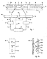
- FIG 1 the device for position detection of moving machine parts on a butt edge of the tact ruler shown, the fasteners 18, 19 on a Cylinder is attachable.
- the bar ruler consists of the Code carrier sections 1a, 1b with a butt edge 2, each Code carrier carries equally spaced code marks 3a, 3b.
- At the Interface is a window opening 1 c.
- Two sensors 4, 8 are arranged on a sensor slide 7.
- the sensor carriage can, for example, on a printer head be attached and is guided with this over the tact ruler.
- the sensors 4, 8 receive optical signals from a transmitter, that behind the sensor carriage in the representation plane according to FIG 7 lies and is therefore not visible.
- both sensors 4, 8 signals corresponding to those guided past the carriage Code marks.
- the sensor 4 is via lines 6a, 6b connected to a counter 5, the from the gear position 2 seen from the crossed code marks 3a recorded and saved.
- Comparator 10 located behind sensor 8 on line 9a a change in the code mark spacing. This change can for example by comparing a test signal with the received code signal can be reached. This is in the comparator 10 integrated a test device 10 '.
- test device 10 determines that a changed The code signal 5 was received via line 9a, the counter 5 separated from line 6b and another counter 11 via Line 17 connected to the sensor 8. This means that at Movement of the sensor carriage 7 over the contact point of the two Code carrier 1a, 1b the signal no longer in counter 5, but is stored in the counter 11.
- a cylindrical machine part such as. a shaft, a hollow cylinder or one Drive wheel
- With a larger circumference of the cylindrical Parts can also be arranged in series with several rulers be, the circuit being in the running direction one after the other arranged sensors, as described in the previous example, he follows.
- the accuracy of the device according to the invention can also be improved in that when starting and braking the Sensor carriage 7 a correspondingly changed test signal for the starting and braking process is made available. Thereby it is avoided that the received in the acceleration state Code signals due to their changed structure as Indicators of a change in the code carrier can be understood.
- a further development of the sensor / emitter unit consists in that the emitter 31 between the sensors 32 and 33 on the Transport carriage 34 is arranged.
- the code carriers are then provided with a reflective layer so that the emitter 31 emitted signals are reflected and at an angle of the sensors 32, 33 are received.
- FIG 1b the situation is in cross section through a tact ruler and a sensor slide is shown.
- the emitter 31 emitted light beams 31a, 31b are marked with dash marks 35 provided surface of the tact ruler 36 reflected and received by sensors 32, 33.
- dash marks 35 provided surface of the tact ruler 36 reflected and received by sensors 32, 33.
- sensors 32, 33 Of course an arrangement of several sensors is also possible, which in the top view of a sensor slide 34 shown in Figure 1a is.
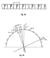
- FIG 2 is a moving clock ruler 22 with different Barcodes 21 provided.
- An optical one emitted by the emitter 20 Signal is received by a sensor 23, which is an electrical Clock signal according to the bar code marking passes on a counter.
- the timing ruler 22 consists of two timing ruler sections 22a, 22b, which are provided with offset bar code markings 21a, 21b are.
- the sensor unit is made up of two individual sensors 23a, 23b, which are in the direction of movement are arranged one behind the other.
- the sensor 23b lying in the front in the direction of movement switches on Reaching a new clock ruler section 21b a counter 25 of the first sensor 23a and then counts the bar code marks 21b of the new cycle ruler section 22b.
- the counted Sections are stored in a transfer unit 27.
- the counter 26 of the second sensor 23b shut down. Now the first counter 25 continues to count, whereby those passed on from the second counter 26 to the transfer unit Signals with the content of the first counter 25 added up become.
- comparators 28, 29 with the individual sensors 23a, 23b connected. These comparators can change bar code markings determine by comparison with test signals and the corresponding switching operations of the counters 25, 26 and trigger the transfer unit 27.
- the circuit sequence described is not only in one direction, but effective in every direction. It happens only that the switching time is sufficient for the sensors, so that no window opening runs past the sensor without being detected and to be compensated.
Landscapes
- Physics & Mathematics (AREA)
- General Physics & Mathematics (AREA)
- Engineering & Computer Science (AREA)
- Signal Processing (AREA)
- Length Measuring Devices By Optical Means (AREA)
- Optical Transform (AREA)
- Length Measuring Devices With Unspecified Measuring Means (AREA)
Claims (2)
- Dispositif pour détecter la position de pièces de machine en déplacement cyclique, en particulier en rotation, comprenant un émetteur (20) optique produisant des signaux, et au moins un support de codes (1), réalisé sous la forme d'une règle de cadencement, et doté de marques de codage (3) maintenues à la même distance à travers des ouvertures de fenêtre, lesdites marques étant susceptibles d'être palpées par un premier capteur (4) relié à un premier compteur (5) via des premières lignes (6a, 6b) qui transmettent un signal de codage fourni par le capteur,
caractérisé en ce quedans le cas où il existe plusieurs règles de cadencement, ou tronçons de règles de cadencement, il se produit des emplacements d'aboutement avec un intervalle dont la largeur diffère de celle des ouvertures de fenêtre,en ce qu'il est prévu un deuxième capteur (8) agencé à côté du premier capteur (4) sur un chariot de capteur (7), ledit deuxième capteur étant relié à un premier comparateur (10) via une deuxième ligne (9a), ledit premier comparateur (10) contenant un premier dispositif de vérification (10') pour les signaux de codage reçus via une deuxième ligne (9a) en coïncidence avec les ouvertures de fenêtre palpées,en ce que le premier comparateur (10) comprend une troisième ligne (17) pour des signaux de codage modifiés, dont la largeur d'écartement est modifiée par comparaison aux marques de codage (3) agencées sur le support de codes (1),en ce que la troisième ligne (17) pour les signaux de codage modifiés est reliée à un deuxième compteur (11),en ce qu'il est prévu un autre comparateur (12) agencé entre le premier capteur (4) et le premier compteur (5),ledit autre comparateur (12) contenant un autre dispositif de vérification (12') pour les signaux de codage reçus via la première ligne (6a) et correspondant à la largeur des ouvertures de fenêtre,en ce qu'il est prévu des moyens de commande afin de connecter l'autre dispositif de vérification (12') avec une unité de transfert (13) dans laquelle des signaux de codage peuvent être mémorisés en cas de divergence dans la largeur d'écartement des marques de codage,en ce que l'unité de transfert (13) est reliée au deuxième compteur (11) via une quatrième ligne (15),en ce qu'à l'unité de transfert (13) est raccordée une cinquième ligne (16), laquelle est reliée au premier compteur (5) pour la sommation des signaux de codage, eten ce qu'il est prévu un moyen de commande qui, par l'intermédiaire des dispositifs de vérification (10', 12'), soit sépare le premier compteur (5) vis-à-vis des premières lignes (6a, 6b) lorsque le deuxième compteur (11) mémorise les signaux de codage modifiés, soit relie le premier compteur (5) avec les premières lignes (6a, 6b) pour la réception de nouveaux signaux provenant du premier capteur (4). - Procédé pour la détermination de position de pièces de machine en mouvement, dans lequel un signal optique provenant d'un émetteur (20) via une règle de cadencement (22) pourvue d'un marquage à codes barres (21) est reçu par un détecteur (23), et le détecteur (23) transmet à un compteur un signal de cadencement électrique correspondant au marquage à codes barres,
caractérisé en ce quela règle de cadencement (22) est fixée sur un cylindre en rotation, et elle est pourvue d'au moins deux marquages à codes barres (21a, 21b) différents l'un de l'autre, qui sont respectivement associés à des tronçons différents de règle de cadencement,en ce que l'unité de détection est formée de deux détecteurs individuels (23a, 23b), parmi lesquels le détecteur (23b) disposé en avant dans la direction de déplacement (24) arrête un premier compteur (25) du deuxième détecteur (23a) lorsqu'il atteint un nouveau tronçon de règle de cadencement avec un marquage à codes barres modifié (21b), et compte les marquages à codes barres (21b) du nouveau tronçon de règle de cadencement et mémorise dans un autre compteur (26) jusqu'à ce que le deuxième détecteur (23a) a également atteint le nouveau tronçon de règle de cadencement (21b), et met alors à l'arrêt l'autre compteur (26) du premier détecteur (23b) tandis que le premier compteur (25) poursuit son décompte et reprend par sommation les signaux de cadencement mémorisés dans l'autre compteur (26), eten ce qu'au passage d'un tronçon de règle de cadencement à l'autre, par comparaison du signal de codage mesuré avec un signal de contrôle, on reconnaít un écart d'erreur, et cette erreur est éliminée par répartition régulière sur les tronçons de marquage de codage sommés.
Applications Claiming Priority (2)
| Application Number | Priority Date | Filing Date | Title |
|---|---|---|---|
| DE19628765 | 1996-07-17 | ||
| DE19628765A DE19628765B4 (de) | 1996-07-17 | 1996-07-17 | Verfahren und Vorrichtung zur Positionsbestimmung von nicht-geradlinig bewegten, insbesondere rotierenden Maschinenteilen |
Publications (2)
| Publication Number | Publication Date |
|---|---|
| EP0819913A1 EP0819913A1 (fr) | 1998-01-21 |
| EP0819913B1 true EP0819913B1 (fr) | 2001-10-17 |
Family
ID=7800036
Family Applications (1)
| Application Number | Title | Priority Date | Filing Date |
|---|---|---|---|
| EP97111288A Expired - Lifetime EP0819913B1 (fr) | 1996-07-17 | 1997-07-04 | Procédé et dispositif pour positionner des pièces de machine à déplacement cyclique et plus particulièrement rotationnel |
Country Status (4)
| Country | Link |
|---|---|
| US (1) | US5959295A (fr) |
| EP (1) | EP0819913B1 (fr) |
| JP (1) | JP2945885B2 (fr) |
| DE (2) | DE19628765B4 (fr) |
Cited By (2)
| Publication number | Priority date | Publication date | Assignee | Title |
|---|---|---|---|---|
| US9651412B2 (en) | 2011-01-31 | 2017-05-16 | Sage Vision Inc. | Bottle dispenser having a digital volume display |
| US10176591B2 (en) | 2012-06-15 | 2019-01-08 | Sage Vision, Inc. | Absolute position detection |
Families Citing this family (27)
| Publication number | Priority date | Publication date | Assignee | Title |
|---|---|---|---|---|
| US6822931B2 (en) | 2001-12-13 | 2004-11-23 | Vision Works, Llc | Timing system and device and method for making the same |
| US7813226B2 (en) | 2002-12-13 | 2010-10-12 | Vision Works Ip Corporation | Timing system and device and method for making the same |
| US7254095B1 (en) | 2002-12-13 | 2007-08-07 | Vision Works, Llc | Timing system and device and method for making the same |
| US8717854B2 (en) | 2002-12-13 | 2014-05-06 | Vision Works Ip Corporation | Environment dependent—temperature independent color changing label |
| DE10300918B4 (de) * | 2003-01-13 | 2014-11-06 | Robert Bosch Gmbh | Vorrichtung und Verfahren zum Erfassen der Relativbewegung zweier relativ zueinander bewegbarer Maschinenteile |
| JP4751032B2 (ja) * | 2004-04-22 | 2011-08-17 | 株式会社森精機製作所 | 変位検出装置 |
| US7191943B2 (en) * | 2004-07-28 | 2007-03-20 | Caterpillar Inc | Robust barcode and reader for rod position determination |
| WO2010099340A2 (fr) * | 2009-02-26 | 2010-09-02 | Vision Works Ip Corporation | Étiquette changeant de couleur en fonction de la durée, mais non de la température |
| AT508874B1 (de) * | 2009-09-17 | 2012-03-15 | Piezocryst Advanced Sensorics | Vorrichtung zur gewinnung von winkelsignalen |
| ATE534017T1 (de) * | 2010-02-09 | 2011-12-15 | Sick Stegmann Gmbh | Messvorrichtung zur absolutwertbestimmung von längen oder winkeln mit aus einzelnen teilstücken zusammengesetzter aktiver massverkörperung |
| DE102010061738A1 (de) * | 2010-11-22 | 2012-04-26 | Baumer Innotec Ag | Verfahren und Inkrementalwertgeber zur Bestimmung einer Istlage eines Körpers entlang eines Messweges mit einer wenigstens eine Lücke aufweisenden Maßverkörperung |
| DE102010061737A1 (de) * | 2010-11-22 | 2012-05-24 | Baumer Innotec Ag | Absolutwertgeber mit Sprungstelle in kodierter Absolutlage |
| WO2013067019A1 (fr) * | 2011-11-01 | 2013-05-10 | Vision Works Ip Corporation | Système et dispositif de chronométrage et procédé pour réaliser ceux-ci |
| US9298167B2 (en) | 2011-12-23 | 2016-03-29 | Vision Works Ip Corporation | Timing system and device and method for making the same |
| WO2016040075A1 (fr) | 2014-09-08 | 2016-03-17 | Vision Works Ip Corporation | Indicateurs pour variables externes constitué de cellules de déplétion singulières et multiples |
| US9602706B2 (en) | 2014-12-01 | 2017-03-21 | Canon Kabushiki Kaisha | Rotatable operating member and electronic device having the same |
| JP6585728B2 (ja) | 2015-02-23 | 2019-10-02 | リ−コール,インコーポレイティド | 生検標本蛍光撮像装置および方法 |
| WO2016210340A1 (fr) | 2015-06-26 | 2016-12-29 | Li-Cor, Inc. | Imageur d'échantillon de biopsie par fluorescence et procédés |
| US10489964B2 (en) | 2016-04-21 | 2019-11-26 | Li-Cor, Inc. | Multimodality multi-axis 3-D imaging with X-ray |
| WO2017223378A1 (fr) | 2016-06-23 | 2017-12-28 | Li-Cor, Inc. | Clignotement de couleur complémentaire pour présentation d'image multicanal |
| US10993622B2 (en) | 2016-11-23 | 2021-05-04 | Li-Cor, Inc. | Motion-adaptive interactive imaging method |
| DE102017100506A1 (de) * | 2017-01-12 | 2018-07-12 | Sick Ag | Optoelektronisches Positionserfassungssystem und Verfahren zur Positionsbestimmung |
| US10318604B2 (en) | 2017-02-13 | 2019-06-11 | Vision Works Ip Corporation | Electronically readable system and device with changing codes |
| WO2018200261A1 (fr) | 2017-04-25 | 2018-11-01 | Li-Cor, Inc. | Imageur d'échantillon de biopsie à vue latérale rotative et orientée de haut en bas et procédés |
| EP3892962B1 (fr) * | 2020-04-08 | 2023-03-08 | Dr. Johannes Heidenhain GmbH | Agencement pour une mesure de position |
| US11828589B2 (en) * | 2021-08-10 | 2023-11-28 | United States Postal Service | Length gauge |
| DE102023209283A1 (de) * | 2023-09-22 | 2025-03-27 | Pepperl+Fuchs Se | Verfahren und Vorrichtung zur Bestimmung der Position eines Objekts |
Family Cites Families (8)
| Publication number | Priority date | Publication date | Assignee | Title |
|---|---|---|---|---|
| DE1938377B2 (de) * | 1969-07-29 | 1970-11-19 | Leitz Ernst Gmbh | Digitale Absolut-Messanordnung mit Synchronisation des Ziffernsprungs in den Grobstellen der Anzeige |
| DE2730715C2 (de) * | 1974-07-26 | 1991-08-29 | Heinz 5121 Ostermiething Rieder | Einrichtung zur Längenmessung |
| AT376298B (de) * | 1976-08-19 | 1984-10-25 | Rieder Heinz | Einrichtung zur laengenmessung |
| JPS6053190B2 (ja) * | 1976-10-15 | 1985-11-25 | 株式会社デンソー | 回転基準位置検出装置 |
| AT385355B (de) * | 1981-06-22 | 1988-03-25 | Rieder Heinz | Inkrementales lagemesssystem |
| EP0349792B1 (fr) * | 1988-07-07 | 1992-10-07 | Oerlikon Geartec AG | Système de lecture de position pour un élément de machine-outil qui peut tourner de plus de 360 degrés |
| JP2720012B2 (ja) * | 1993-09-27 | 1998-02-25 | ブラウン ポール−ビルヘルム | エンコーダ |
| DE19621015C2 (de) * | 1996-05-24 | 1999-07-08 | Braun Paul W | Verfahren und Vorrichtung zur Positionierung von bewegten Maschinenteilen |
-
1996
- 1996-07-17 DE DE19628765A patent/DE19628765B4/de not_active Expired - Fee Related
-
1997
- 1997-07-04 EP EP97111288A patent/EP0819913B1/fr not_active Expired - Lifetime
- 1997-07-04 DE DE59704935T patent/DE59704935D1/de not_active Expired - Fee Related
- 1997-07-11 JP JP9202383A patent/JP2945885B2/ja not_active Expired - Fee Related
- 1997-07-15 US US08/903,200 patent/US5959295A/en not_active Expired - Fee Related
Cited By (3)
| Publication number | Priority date | Publication date | Assignee | Title |
|---|---|---|---|---|
| US9651412B2 (en) | 2011-01-31 | 2017-05-16 | Sage Vision Inc. | Bottle dispenser having a digital volume display |
| US10176591B2 (en) | 2012-06-15 | 2019-01-08 | Sage Vision, Inc. | Absolute position detection |
| US11816856B2 (en) | 2012-06-15 | 2023-11-14 | Sage Vision Inc. | Absolute position detection |
Also Published As
| Publication number | Publication date |
|---|---|
| DE19628765A1 (de) | 1998-01-22 |
| JPH1082612A (ja) | 1998-03-31 |
| DE19628765B4 (de) | 2007-04-05 |
| EP0819913A1 (fr) | 1998-01-21 |
| JP2945885B2 (ja) | 1999-09-06 |
| DE59704935D1 (de) | 2001-11-22 |
| US5959295A (en) | 1999-09-28 |
Similar Documents
| Publication | Publication Date | Title |
|---|---|---|
| DE19628765B4 (de) | Verfahren und Vorrichtung zur Positionsbestimmung von nicht-geradlinig bewegten, insbesondere rotierenden Maschinenteilen | |
| DE3311204C2 (fr) | ||
| EP0268558B1 (fr) | Appareil pour la mesure de longueurs ou d'angles | |
| DE2730715C2 (de) | Einrichtung zur Längenmessung | |
| DE3144334C2 (de) | Wegmeßeinrichtung mit Referenzmarken | |
| DE69815919T2 (de) | Positionskodierer | |
| EP0555507B1 (fr) | Capteur de position | |
| DE4428590C2 (de) | Positionsmeßeinrichtung | |
| DE4244276B4 (de) | Anordnung zum Messen der Lage einer Bogenkante auf der Oberfläche eines rotierenden Zylinders | |
| EP0530176B1 (fr) | Dispositif de mesure linéaire ou angulaire | |
| DE19621015C2 (de) | Verfahren und Vorrichtung zur Positionierung von bewegten Maschinenteilen | |
| AT410485B (de) | Positionsmesseinrichtung | |
| EP1995566A2 (fr) | Echelle pour un dispositif de mesure de position et dispositif de mesure de position | |
| EP2017678B2 (fr) | Procédé et dispositif de transmission de signaux d'un dispositif de mesure de position vers une unité d'évaluation | |
| EP1102040A1 (fr) | Capteur de position | |
| DE3322897C2 (fr) | ||
| DE3412063C2 (fr) | ||
| EP2116814B1 (fr) | Dispositif de mesure destiné à la détermination d'une position et/ou d'une vitesse | |
| DE4015099A1 (de) | Messwandler | |
| DE2333530A1 (de) | Messanordnung zur umformung einer entfernung in ein kodiertes signal | |
| EP0421024A1 (fr) | Dispositif photoélectrique de mesure de position | |
| DE4244178C2 (de) | Längen- oder Winkelmeßeinrichtung | |
| EP1770375B1 (fr) | Dispositif de mesure de position comprenant deux echelles de mesure dont les pistes codées se chevauchent mutuellement | |
| DE3829636C2 (de) | Positionserfassungssystem | |
| DE3409544C2 (fr) |
Legal Events
| Date | Code | Title | Description |
|---|---|---|---|
| PUAI | Public reference made under article 153(3) epc to a published international application that has entered the european phase |
Free format text: ORIGINAL CODE: 0009012 |
|
| AK | Designated contracting states |
Kind code of ref document: A1 Designated state(s): DE FR GB |
|
| 17P | Request for examination filed |
Effective date: 19980619 |
|
| AKX | Designation fees paid |
Free format text: DE FR GB |
|
| RBV | Designated contracting states (corrected) |
Designated state(s): DE FR GB |
|
| 17Q | First examination report despatched |
Effective date: 20000407 |
|
| RTI1 | Title (correction) |
Free format text: METHOD AND APPARATUS FOR THE POSITIONING OF CYCLICALLY MOVING, ESPECIALLY ROTATING MACHINE PARTS |
|
| RTI1 | Title (correction) |
Free format text: METHOD AND APPARATUS FOR THE POSITIONING OF CYCLICALLY MOVING, ESPECIALLY ROTATING MACHINE PARTS |
|
| GRAG | Despatch of communication of intention to grant |
Free format text: ORIGINAL CODE: EPIDOS AGRA |
|
| GRAG | Despatch of communication of intention to grant |
Free format text: ORIGINAL CODE: EPIDOS AGRA |
|
| GRAH | Despatch of communication of intention to grant a patent |
Free format text: ORIGINAL CODE: EPIDOS IGRA |
|
| RTI1 | Title (correction) |
Free format text: METHOD AND APPARATUS FOR THE POSITIONING OF CYCLICALLY MOVING, ESPECIALLY ROTATING MACHINE PARTS |
|
| GRAH | Despatch of communication of intention to grant a patent |
Free format text: ORIGINAL CODE: EPIDOS IGRA |
|
| GRAA | (expected) grant |
Free format text: ORIGINAL CODE: 0009210 |
|
| AK | Designated contracting states |
Kind code of ref document: B1 Designated state(s): DE FR GB |
|
| REF | Corresponds to: |
Ref document number: 59704935 Country of ref document: DE Date of ref document: 20011122 |
|
| REG | Reference to a national code |
Ref country code: GB Ref legal event code: IF02 |
|
| GBT | Gb: translation of ep patent filed (gb section 77(6)(a)/1977) |
Effective date: 20011228 |
|
| ET | Fr: translation filed | ||
| PLBE | No opposition filed within time limit |
Free format text: ORIGINAL CODE: 0009261 |
|
| STAA | Information on the status of an ep patent application or granted ep patent |
Free format text: STATUS: NO OPPOSITION FILED WITHIN TIME LIMIT |
|
| 26N | No opposition filed | ||
| PGFP | Annual fee paid to national office [announced via postgrant information from national office to epo] |
Ref country code: FR Payment date: 20080729 Year of fee payment: 12 |
|
| PGFP | Annual fee paid to national office [announced via postgrant information from national office to epo] |
Ref country code: GB Payment date: 20080723 Year of fee payment: 12 |
|
| PGFP | Annual fee paid to national office [announced via postgrant information from national office to epo] |
Ref country code: DE Payment date: 20080924 Year of fee payment: 12 |
|
| GBPC | Gb: european patent ceased through non-payment of renewal fee |
Effective date: 20090704 |
|
| REG | Reference to a national code |
Ref country code: FR Ref legal event code: ST Effective date: 20100331 |
|
| PG25 | Lapsed in a contracting state [announced via postgrant information from national office to epo] |
Ref country code: FR Free format text: LAPSE BECAUSE OF NON-PAYMENT OF DUE FEES Effective date: 20090731 |
|
| PG25 | Lapsed in a contracting state [announced via postgrant information from national office to epo] |
Ref country code: GB Free format text: LAPSE BECAUSE OF NON-PAYMENT OF DUE FEES Effective date: 20090704 |
|
| PG25 | Lapsed in a contracting state [announced via postgrant information from national office to epo] |
Ref country code: DE Free format text: LAPSE BECAUSE OF NON-PAYMENT OF DUE FEES Effective date: 20100202 |