EP0819924A2 - Appareil et procédé pour la mesure des caractéristiques d'impulsions optiques - Google Patents
Appareil et procédé pour la mesure des caractéristiques d'impulsions optiques Download PDFInfo
- Publication number
- EP0819924A2 EP0819924A2 EP97112135A EP97112135A EP0819924A2 EP 0819924 A2 EP0819924 A2 EP 0819924A2 EP 97112135 A EP97112135 A EP 97112135A EP 97112135 A EP97112135 A EP 97112135A EP 0819924 A2 EP0819924 A2 EP 0819924A2
- Authority
- EP
- European Patent Office
- Prior art keywords
- optical
- output
- path length
- beam splitter
- optical path
- Prior art date
- Legal status (The legal status is an assumption and is not a legal conclusion. Google has not performed a legal analysis and makes no representation as to the accuracy of the status listed.)
- Withdrawn
Links
Images


Classifications
-
- G—PHYSICS
- G04—HOROLOGY
- G04F—TIME-INTERVAL MEASURING
- G04F13/00—Apparatus for measuring unknown time intervals by means not provided for in groups G04F5/00 - G04F10/00
- G04F13/02—Apparatus for measuring unknown time intervals by means not provided for in groups G04F5/00 - G04F10/00 using optical means
- G04F13/026—Measuring duration of ultra-short light pulses, e.g. in the pico-second range; particular detecting devices therefor
-
- G—PHYSICS
- G01—MEASURING; TESTING
- G01J—MEASUREMENT OF INTENSITY, VELOCITY, SPECTRAL CONTENT, POLARISATION, PHASE OR PULSE CHARACTERISTICS OF INFRARED, VISIBLE OR ULTRAVIOLET LIGHT; COLORIMETRY; RADIATION PYROMETRY
- G01J11/00—Measuring the characteristics of individual optical pulses or of optical pulse trains
Definitions
- the present invention relates to an apparatus and a method for measuring characteristics of optical pulses.
- the auto-correlation method using non-linear optical crystal can detect pulses having a pulse width as short as 0.1 femto-second, it cannot detect weak optical pulses because it utilizes the higher-order non-linear optical effect. Moreover, since the measurable pulse width depends on the length of the crystal and the measurable wavelength depends on the material of the crystal, different crystals must be used for different purposes.
- the heterodyne method As a pulse width measuring method with highly sensitivity, the heterodyne method has been proposed (Reference : Tomaru et al. : "Optical pulse auto-correlation method using the heterodyne method ", 43rd Applied Physics Symposium 26a-A-2,1996). In this method, the measured pulse width becomes broader than the actual one, due to the secondary dispersion of the frequency modulator used in the measuring optical system. Moreover, since optical detection of the heterodyne component of the higher harmonics is required, the optical detector must have an operation band width as broad as 10 GHz.
- An object of the present invention is to solve the above-described problems and to provide an apparatus and method for measuring characteristics of optical pulses with high sensitivity and high stability which do not require a broadband type optical detector.
- an apparatus for measuring optical pulses characteristics comprising a beam splitter for splitting optical pulses to be measured, means for modulating the optical path length of one of the light beams output from the beam splitter, means for changing the optical path length of the other light beam output from the beam splitter, an optical mixer for mixing two output light beams, an optical detector for detecting a light beam output from the optical mixer, and means for measuring the amplitude of an AC signal output from the optical detector.
- a method for measuring optical pulses characteristics comprising the steps of disposing a beam splitter for splitting optical pulses to be measured, means for modulating the optical path length of one of the light beams output from the beam splitter, means for changing the optical path length of the other light beam output from the beam splitter, an optical mixer for mixing two output light beams, an optical detector for detecting a light beam output from the optical mixer, and means for measuring the amplitude of an AC signal output from the optical detector; and after splitting optical pulses by the beam splitter, modulating the optical path length of one of the light beams, and performing heterodyne detection in order to measure the AC signal component which is generated by the modulation of the optical path length.
- an apparatus for measuring optical pulses characteristics comprising a beam splitter for splitting optical pulses to be measured, means for modulating the optical path length of one of the light beams output from the beam splitter, means for changing the optical path length of the other light beam output from the beam splitter, means for chopping one of the light beams output from the beam splitter, an optical mixer for mixing the two output light beams, an optical detector for detecting a light beam from the optical mixer, detecting means for detecting the amplitude of an AC signal output from the optical detector, and synchronous detecting means for synchronously detecting the amplitude of the output from the detecting means.
- a method for measuring optical pulses characteristics comprising the steps of disposing a beam splitter for splitting optical pulses to be measured, means for modulating the optical path length of one of the light beams output from the beam splitter, means for changing the optical path length of the other light beam output from the beam splitter, means for chopping one of the light beams output from the beam splitter, an optical mixer for mixing the two output light beams, an optical detector for detecting a light beam from the optical mixer, detecting means for detecting the amplitude of an AC signal output from the optical detector, and synchronous detecting means for synchronously detecting the amplitude of the output from the detecting means; and after splitting optical pulses by the beam splitter, chopping one of the light beams, modulating the optical path length of one of the light beams, performing heterodyne detection in order to detect the AC signal component which is generated by the modulation of the optical path length, and measuring the detected AC signal component synchronously with the
- an apparatus for measuring optical pulse characteristics comprising a beam splitter for splitting optical pulses to be measured, means for changing the optical path length of one of the light beams output from the beam splitter, an optical mixer for mixing the two output light beams, an optical detector for detecting the output light from the optical mixer, and detecting means for detecting an AC signal output from the optical detector.
- a method for measuring optical pulse characteristics comprising the step of disposing a beam splitter for splitting optical pulses to be measured, means for changing the optical path length of one of the light beams output from the beam splitter, an optical mixer for mixing the two output light beams, an optical detector for detecting the output light from the optical mixer, and detecting means for detecting an AC signal output from the optical detector, and measuring an AC signal component which is generated by simultaneously changing the optical path length difference through use of the means for changing the optical path length.
- Accurate measurement of the optical pulse characteristics, especially optical pulse width, and detection of the optical pulses can be realized by measuring the amplitude of a stable AC signal generated by modulation of the optical path length difference of the interferometer, without stabilization of the interferometer.
- Variations in the optical path length difference in the homodyne interferometer directly causes a change in the output signal, and generally requires stabilization of the interferometer.
- negative feedback control is used for stabilization.
- the measurement procedure is started without an overlapping of optical pulses, i.e., without an output of the interferometer.
- a control signal is not available for stabilization, and stabilization is impossible.
- one of the optical paths of the interferometer is changed in order to obtain an correlation length. If the interferometer is controlled for stabilization at this time, the control signal changes in accordance with the change in the optical path, and separation of the control signal and the measurement signal becomes difficult.
- the interference stripes change in accordance with the modulation speed and the amplitude, and an AC signal is generated.
- the amplitude of this AC signal is the same as that of the visibility. Therefore, the auto-correlation signal is obtained by measuring the amplitude of the output of the homodyne detection while changing the optical path length difference of the interferometer. Since in this case the instability due to the unstable interferometer is converted to the changes of phase and frequency, the amplitude change becomes very small.
- This interferometer uses the homodyne detection method. Therefore, by using a local oscillation light of sufficient intensity in one of the optical paths, the intensity of the signal light on the other optical path can be very small, and sensitive optical pulse detection can be realized. Moreover, the required bandwidth for detection of an AC signal that is generated through modulation of the optical path length difference is sufficient for the optical detector used here. For example, if a triangular wave with a frequency of 100 Hz and an amplitude of 10 times the optical wavelength is used for the optical path modulation, the frequency of the generated AC signal becomes 2 kHz, which can be detected with an ordinary optical detector.
- the pulse width of the optical pulses to be measured is obtained by measuring the amplitude of the output of the homodyne detection while changing the optical path length difference.
- the resolution of pulse width measurement is limited. If the modulation amplitude is half the wavelength of the optical pulses to be measured, one cycle period of the AC signal is generated by a single reciprocal amplitude change, thus enabling amplitude measurement of the AC signal.
- a half wavelength corresponds to the resolution of the pulse location. If the optical wavelength is 1 ⁇ m and the intensity profile of optical pulse is Sech 2 -type, from Equation (1) the resolution becomes about 1.5 fsec, which is very high resolution.
- FIG. 1 is a schematic diagram of an optical pulse characteristic measuring apparatus according to a first embodiment of the present invention.
- the optical pulse characteristic measuring apparatus comprises a beam splitter 1, a mirror 2, a delay element 3 for adjustment of optical path length difference, a signal generator 4 for modulation of optical path length difference, a mirror 5 for modulation of optical path length difference, a delay element 6 for correlation length measurement, an optical wave mixer 7, optical detectors 8 and 9, a differential amplifier 10, a bandpass filter 11 and an AC voltmeter 12.
- the signal generator 4 for modulation of optical path length difference and the mirror 5 for modulation of optical path length difference serve as means for modulation of optical path length
- the differential amplifier 10, the bandpass filter 11, and the AC voltmeter 12 serve as means for measuring the amplitude of an AC signal.
- the beam splitter 1 splits the optical pulses to be measured, and the optical mixer 7 mixes two optical beams.
- Half mirrors, non-polarized beam splitters or optical directional couplers may be used.
- the mirror 5 for modulation of optical path length difference is sufficient if it produces oscillation of several times the optical wavelength, and may comprise a piezo element and a mirror attached to the piezo element. Moreover, the action of the mirror 5 for modulation of path length difference is to continuously change the phase of the light, and alternative construction can be used if the same level of phase change is obtained.
- the delay element 6 for correlation length measurement is used when the pulse width is measured, and its delay distance depends on the pulse width of the optical pulses to be measured.
- the delay element 3 for adjustment of optical path length difference is used for equalization of the two optical path lengths between the beam splitter 1 and the optical wave mixer 7.
- the mirror 5 for modulation of the optical path length difference is optionally placed at one of the delay elements.
- the present embodiment including two optical detectors 8 and 9 and a differential amplifier 10 is obviously superior in terms of S-N ratio, because the amplitude noise in the incident light is suppressed and the noise is of the shot noise level.
- the optical pulses to be measured are introduced at the incident end, and split at the beam splitter 1.
- One of the resultant light beams (a first light beam) is reflected by the mirror 2 as a local oscillation light of homodyne detection and is adjusted in the delay element 3 so as to have the same optical path length as that of the other light beam (a second light beam).
- the first light beam is led to the optical mixer 7.
- the second light beam is reflected by the mirror 5, which is controlled by the signal from the signal generator 4 for modulation of optical path length difference.
- the second light beam is then reflected by the delay element 6 and is led to the optical mixer 7.
- the two optical signals combined at the optical mixer 7 are detected by the optical detectors 8 and 9.
- the AC signal component generated by modulation of the optical path length difference is amplified up to a measurable voltage by the differential amplifier 10.
- the bandpass filter 11 passes only the AC signal Component generated by modulation of the optical path length difference, thereby improving the S-N ratio.
- the S-N ratio is improved when the AC signal component generated by modulation of the optical path length difference is measured in the first embodiment.
- the bandpass filter 11 is, of course, adjusted so as to pass the AC signal component generated by modulation of the optical path length difference.
- the phase of the output AC signal of this embodiment represents the phase difference between the local oscillation light and the signal light.
- the phase characteristics of the optical pulses can be determined through measurement of the phase of this output AC signal. Measurement of the phase requires another AC signal of standard phas, which cannot be obtained in this embodiment. Therefore, there is provided a separate standard AC signal of a frequency substantially equal to that of the output AC signal, and the phase difference between the standard signal and the output AC signal is measured by a phase detector.
- the output of the phase detector includes a static phase difference between the standard signal and the output AC signal. The static phase difference is substantially linear if the measurement time is short, and the phase characteristics of the optical pulses can be obtained by subtracting this linear component from the measured result.
- FIG. 2 is a schematic diagram of a second embodiment of the optical pulse characteristic measuring apparatus of the present invention.
- the same numerals are assigned to elements corresponding to those in FIG. 1, and detailed descriptions of these elements will be omitted.
- the present embodiment is characterized by the addition of an optical chopper 13, a detector 14, and a synchronous detector 15 to the first embodiment.
- the optical chopper 13 serve as means for chopping the light
- the synchronous detector 15 serve as synchronous detection means for measuring amplitude of the AC signal detector output synchronously with the operation of the optical chopper 13.
- an ordinary RC type smoothing circuit can be disposed after the detector 15.
- a low pass filter or a bandpass filter having steep cut-off characteristics is used, the S-N ratio of the high efficiency synchronous signal component can be improved.
- An ordinary lock-in amplifier may be used as the means for synchronous detection.
- FIG. 3 shows the result of a measurement in which the homodyne detection output of the transform limit pulses from the titan-sapphire laser according to the first embodiment.
- the X axis represents the optical path length difference resulting from the moving distance of the delay element 6 for correlation length measurement
- the Y axis represents the amplitude of the output of the synchronous detector 15.
- the intensity on the local oscillating side was 5 mW, and the intensity on the signal side was 15 fW.
- the resultant optical path length difference of half-maximum width of the auto correlated wave shape was 93.57 ⁇ m, and the pulse width calculated from Equation (1) became 144 fsec.
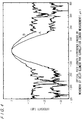
- Curve A shown in FIG. 4 represents the test result of measuring obtained through use of the optical pulse characteristic measuring apparatus according to the second embodiment, the pulses from the titan-sapphire laser (FIG. 3). As can be clearly seen, the S-N ratio of larger than 25 dB was secured. In this case, a lock-in amplifier was used as the synchronous detector and the integration time was set to 1 second.
- Curve B in FIG. 4 represents the test result obtained through use of the optical pulse characteristic measuring apparatus according to the first embodiment. Comparing the two results in this graph, we can see that the results of the second embodiment are more than 10 dB higher in S-N ratio and superior in terms of sensitivity.
- the amplitude of the output of the homodyne detection is proportional to the square root of the product of the respective intensities of the local oscillation light and the signal light. Therefore, under this measurement condition, if the splitting ratio of the incidence side beam splitter is set to 1 : 1, optical pulse width measurement can be performed for incidence light energy of about 8.6 nW with an S-N ratio of higher than 25 dB, which represents excellent sensitivity.
- FIGs. 1 and 2 use a Mach-Zehnder interferometer
- a Michelson interferometer can be substituted for the same use.
- Optical fibers can also be used in some of the components.
- the present invention provides the following effects:
Landscapes
- Physics & Mathematics (AREA)
- General Physics & Mathematics (AREA)
- Spectroscopy & Molecular Physics (AREA)
- Nonlinear Science (AREA)
- Optics & Photonics (AREA)
- Photometry And Measurement Of Optical Pulse Characteristics (AREA)
- Testing Of Optical Devices Or Fibers (AREA)
- Optical Modulation, Optical Deflection, Nonlinear Optics, Optical Demodulation, Optical Logic Elements (AREA)
Applications Claiming Priority (2)
| Application Number | Priority Date | Filing Date | Title |
|---|---|---|---|
| JP185235/96 | 1996-07-16 | ||
| JP18523596A JP3657362B2 (ja) | 1996-07-16 | 1996-07-16 | 光パルス特性測定装置およびその測定方法 |
Publications (2)
| Publication Number | Publication Date |
|---|---|
| EP0819924A2 true EP0819924A2 (fr) | 1998-01-21 |
| EP0819924A3 EP0819924A3 (fr) | 1999-02-10 |
Family
ID=16167255
Family Applications (1)
| Application Number | Title | Priority Date | Filing Date |
|---|---|---|---|
| EP97112135A Withdrawn EP0819924A3 (fr) | 1996-07-16 | 1997-07-16 | Appareil et procédé pour la mesure des caractéristiques d'impulsions optiques |
Country Status (3)
| Country | Link |
|---|---|
| US (1) | US6057919A (fr) |
| EP (1) | EP0819924A3 (fr) |
| JP (1) | JP3657362B2 (fr) |
Families Citing this family (27)
| Publication number | Priority date | Publication date | Assignee | Title |
|---|---|---|---|---|
| JPH11316245A (ja) * | 1998-05-01 | 1999-11-16 | Ando Electric Co Ltd | 電気光学サンプリングオシロスコープ |
| JP3631025B2 (ja) * | 1998-12-24 | 2005-03-23 | アンリツ株式会社 | 波長分散測定装置及び偏波分散測定装置 |
| US6504612B2 (en) | 2000-11-14 | 2003-01-07 | Georgia Tech Research Corporation | Electromagnetic wave analyzer |
| US7450618B2 (en) * | 2001-01-30 | 2008-11-11 | Board Of Trustees Operating Michigan State University | Laser system using ultrashort laser pulses |
| US8208505B2 (en) * | 2001-01-30 | 2012-06-26 | Board Of Trustees Of Michigan State University | Laser system employing harmonic generation |
| US7583710B2 (en) * | 2001-01-30 | 2009-09-01 | Board Of Trustees Operating Michigan State University | Laser and environmental monitoring system |
| US7973936B2 (en) * | 2001-01-30 | 2011-07-05 | Board Of Trustees Of Michigan State University | Control system and apparatus for use with ultra-fast laser |
| AU2002245345A1 (en) * | 2001-01-30 | 2002-08-12 | Board Of Trustees Operating Michigan State University | Control system and apparatus for use with laser excitation or ionization |
| US7609731B2 (en) * | 2001-01-30 | 2009-10-27 | Board Of Trustees Operating Michigan State University | Laser system using ultra-short laser pulses |
| US7567596B2 (en) * | 2001-01-30 | 2009-07-28 | Board Of Trustees Of Michigan State University | Control system and apparatus for use with ultra-fast laser |
| DE10118392A1 (de) * | 2001-04-13 | 2002-11-07 | Zeiss Carl | System und Verfahren zum Bestimmen einer Position oder/und Orientierung zweier Objekte relativ zueinander sowie Strahlführungsanordnung, Interferometeranordnung und Vorrichtung zum Ändern einer optischen Weglänge zum Einsatz in einem solchen System und Verfahren |
| US6933845B2 (en) * | 2003-04-08 | 2005-08-23 | Lockheed Martin Corporation | Photon intrusion detector |
| WO2006088841A1 (fr) * | 2005-02-14 | 2006-08-24 | Board Of Trustees Of Michigan State University | Systeme laser ultra-rapide |
| CN100403190C (zh) * | 2005-06-27 | 2008-07-16 | 西安交通大学 | 相位共轭阿秒和频极化拍的测量方法 |
| US8618470B2 (en) | 2005-11-30 | 2013-12-31 | Board Of Trustees Of Michigan State University | Laser based identification of molecular characteristics |
| WO2007145702A2 (fr) * | 2006-04-10 | 2007-12-21 | Board Of Trustees Of Michigan State University | Système d'usinage par laser |
| US8311069B2 (en) | 2007-12-21 | 2012-11-13 | Board Of Trustees Of Michigan State University | Direct ultrashort laser system |
| CN100595537C (zh) * | 2008-02-01 | 2010-03-24 | 北京工业大学 | 飞秒激光脉冲自相关测试仪及其方法 |
| EP2211430A3 (fr) * | 2009-01-23 | 2015-05-27 | Board of Trustees of Michigan State University | Système d'autocorrélation laser |
| US8861075B2 (en) | 2009-03-05 | 2014-10-14 | Board Of Trustees Of Michigan State University | Laser amplification system |
| US8630322B2 (en) * | 2010-03-01 | 2014-01-14 | Board Of Trustees Of Michigan State University | Laser system for output manipulation |
| WO2012140922A1 (fr) * | 2011-04-15 | 2012-10-18 | 日本電気株式会社 | Récepteur cohérent |
| CN103048053B (zh) * | 2012-12-07 | 2015-09-02 | 中国科学院西安光学精密机械研究所 | 单次激光信噪比探测装置 |
| CN104019911A (zh) * | 2014-06-18 | 2014-09-03 | 苏州紫光伟业激光科技有限公司 | 实时宽频反射性自相干仪 |
| CN104048814B (zh) * | 2014-06-25 | 2016-07-06 | 首都师范大学 | 太赫兹波导测试系统 |
| CN104503081A (zh) * | 2014-12-15 | 2015-04-08 | 哈尔滨工程大学 | 一种基于环形光纤反射镜的共光路菲索干涉仪型光程相关器 |
| CN112033279B (zh) * | 2020-07-24 | 2021-12-10 | 长沙麓邦光电科技有限公司 | 白光干涉系统 |
Family Cites Families (8)
| Publication number | Priority date | Publication date | Assignee | Title |
|---|---|---|---|---|
| US4480192A (en) * | 1982-02-16 | 1984-10-30 | The University Of Rochester | Optical pulse correlation measurement |
| JPS61222290A (ja) * | 1985-03-28 | 1986-10-02 | Hamamatsu Photonics Kk | レ−ザパルス列のジツタ測定装置 |
| US4792230A (en) * | 1986-09-08 | 1988-12-20 | Nippon Telegraph And Telephone Corporation | Method and apparatus for measuring ultrashort optical pulses |
| US4907885A (en) * | 1986-09-24 | 1990-03-13 | The United States Of America As Represented By The United States Department Of Energy | Heterodyne laser diagnostic system |
| JPS63208729A (ja) * | 1987-02-25 | 1988-08-30 | Hitachi Ltd | オ−トコリレ−タ |
| US4973160A (en) * | 1989-04-06 | 1990-11-27 | Yoshihiro Takiguchi | SHG autocorrelator |
| US5530544A (en) * | 1992-10-26 | 1996-06-25 | Sandia Corporation | Method and apparatus for measuring the intensity and phase of one or more ultrashort light pulses and for measuring optical properties of materials |
| US5585913A (en) * | 1994-04-01 | 1996-12-17 | Imra America Inc. | Ultrashort pulsewidth laser ranging system employing a time gate producing an autocorrelation and method therefore |
-
1996
- 1996-07-16 JP JP18523596A patent/JP3657362B2/ja not_active Expired - Fee Related
-
1997
- 1997-07-11 US US08/893,647 patent/US6057919A/en not_active Expired - Fee Related
- 1997-07-16 EP EP97112135A patent/EP0819924A3/fr not_active Withdrawn
Also Published As
| Publication number | Publication date |
|---|---|
| US6057919A (en) | 2000-05-02 |
| JP3657362B2 (ja) | 2005-06-08 |
| JPH1030965A (ja) | 1998-02-03 |
| EP0819924A3 (fr) | 1999-02-10 |
Similar Documents
| Publication | Publication Date | Title |
|---|---|---|
| US6057919A (en) | Apparatus and method for measuring characteristics of optical pulses | |
| US4005936A (en) | Interferometric methods and apparatus for measuring distance to a surface | |
| EP3588015B1 (fr) | Capteur réparti de brillouin et de rayleigh | |
| US5936732A (en) | Apparatus and method for characterizing ultrafast polarization varying optical pulses | |
| EP2708856A1 (fr) | Dispositif et procédé pour la mesure de la distribution de grandeurs physiques dans une fibre optique | |
| US5256968A (en) | Measurement of high-frequency electrical signals by electro-optical effect | |
| JPS6235051B2 (fr) | ||
| US8279438B2 (en) | Optical measuring apparatus | |
| US6025911A (en) | Broadband ultrashort pulse measuring device using non-linear electronic components | |
| US6266145B1 (en) | Apparatus for measurement of an optical pulse shape | |
| JPH06174592A (ja) | 光ファイバの波長分散測定方法 | |
| JP2003270127A (ja) | 光振幅位相時間応答測定装置 | |
| JP3393081B2 (ja) | 光デバイスの特性評価システム | |
| JPH0427843A (ja) | レーザダイオードを用いた低ノイズパルス光源及びこの光源を用いた電圧検出装置 | |
| US4980632A (en) | Electrical signal observing device | |
| JPH09133585A (ja) | 光パルス列測定方法 | |
| JP2972885B1 (ja) | 光ファイバ分散測定方法 | |
| RU2843086C1 (ru) | Распределенный оптоволоконный фазовый датчик виброакустических воздействий и способ его применения | |
| RU232797U1 (ru) | Оптоволоконный фазовый датчик распределенных виброакустических воздействий | |
| JP3453745B2 (ja) | 光ファイバ検査装置 | |
| Tanaka et al. | Profilometry using optical microwaves with different carrier frequencies and two-photon absorption process of photodetector | |
| JP2002509612A (ja) | 波長測定システム | |
| JPH0712679A (ja) | 光共振器周波数特性測定方法および装置 | |
| JP3183472B2 (ja) | 光波長切替特性測定方法および測定装置 | |
| JP2591610Y2 (ja) | 光周波数変調特性測定装置 |
Legal Events
| Date | Code | Title | Description |
|---|---|---|---|
| PUAI | Public reference made under article 153(3) epc to a published international application that has entered the european phase |
Free format text: ORIGINAL CODE: 0009012 |
|
| AK | Designated contracting states |
Kind code of ref document: A2 Designated state(s): DE FR GB |
|
| 17P | Request for examination filed |
Effective date: 19980612 |
|
| PUAL | Search report despatched |
Free format text: ORIGINAL CODE: 0009013 |
|
| AK | Designated contracting states |
Kind code of ref document: A3 Designated state(s): AT BE CH DE DK ES FI FR GB GR IE IT LI LU MC NL PT SE |
|
| AKX | Designation fees paid |
Free format text: DE FR GB |
|
| RAP1 | Party data changed (applicant data changed or rights of an application transferred) |
Owner name: JAPAN SCIENCE AND TECHNOLOGY CORPORATION |
|
| 17Q | First examination report despatched |
Effective date: 20070924 |
|
| STAA | Information on the status of an ep patent application or granted ep patent |
Free format text: STATUS: THE APPLICATION HAS BEEN WITHDRAWN |
|
| 18W | Application withdrawn |
Effective date: 20110704 |