EP0819926A2 - System und Verfahren zur Erfassung von der chromatischen Dispersion in optischen Fasern - Google Patents
System und Verfahren zur Erfassung von der chromatischen Dispersion in optischen Fasern Download PDFInfo
- Publication number
- EP0819926A2 EP0819926A2 EP97304975A EP97304975A EP0819926A2 EP 0819926 A2 EP0819926 A2 EP 0819926A2 EP 97304975 A EP97304975 A EP 97304975A EP 97304975 A EP97304975 A EP 97304975A EP 0819926 A2 EP0819926 A2 EP 0819926A2
- Authority
- EP
- European Patent Office
- Prior art keywords
- fiber
- wavelength
- wavelengths
- signal
- dispersion
- Prior art date
- Legal status (The legal status is an assumption and is not a legal conclusion. Google has not performed a legal analysis and makes no representation as to the accuracy of the status listed.)
- Granted
Links
- 239000006185 dispersion Substances 0.000 title claims abstract description 80
- 238000000034 method Methods 0.000 title claims abstract description 47
- 239000013307 optical fiber Substances 0.000 title claims description 9
- 238000013507 mapping Methods 0.000 title claims 2
- 239000000835 fiber Substances 0.000 claims abstract description 67
- 230000003287 optical effect Effects 0.000 claims abstract description 18
- 239000000523 sample Substances 0.000 claims abstract description 18
- 230000008569 process Effects 0.000 claims abstract description 17
- 238000005259 measurement Methods 0.000 claims abstract description 12
- 230000010355 oscillation Effects 0.000 claims abstract description 10
- 238000012360 testing method Methods 0.000 claims abstract description 9
- 230000003466 anti-cipated effect Effects 0.000 claims description 3
- 230000002123 temporal effect Effects 0.000 abstract description 4
- 238000000253 optical time-domain reflectometry Methods 0.000 description 7
- 230000005540 biological transmission Effects 0.000 description 5
- 230000001066 destructive effect Effects 0.000 description 5
- 229910052691 Erbium Inorganic materials 0.000 description 4
- UYAHIZSMUZPPFV-UHFFFAOYSA-N erbium Chemical compound [Er] UYAHIZSMUZPPFV-UHFFFAOYSA-N 0.000 description 4
- 230000000694 effects Effects 0.000 description 3
- 230000002547 anomalous effect Effects 0.000 description 2
- 230000008859 change Effects 0.000 description 2
- 238000012545 processing Methods 0.000 description 2
- 238000000926 separation method Methods 0.000 description 2
- 230000003595 spectral effect Effects 0.000 description 2
- 238000012935 Averaging Methods 0.000 description 1
- VYPSYNLAJGMNEJ-UHFFFAOYSA-N Silicium dioxide Chemical compound O=[Si]=O VYPSYNLAJGMNEJ-UHFFFAOYSA-N 0.000 description 1
- 238000013459 approach Methods 0.000 description 1
- BJQHLKABXJIVAM-UHFFFAOYSA-N bis(2-ethylhexyl) phthalate Chemical compound CCCCC(CC)COC(=O)C1=CC=CC=C1C(=O)OCC(CC)CCCC BJQHLKABXJIVAM-UHFFFAOYSA-N 0.000 description 1
- 238000004891 communication Methods 0.000 description 1
- 230000007812 deficiency Effects 0.000 description 1
- 230000001419 dependent effect Effects 0.000 description 1
- 238000013461 design Methods 0.000 description 1
- 238000001514 detection method Methods 0.000 description 1
- 238000010586 diagram Methods 0.000 description 1
- 238000004134 energy conservation Methods 0.000 description 1
- 238000004146 energy storage Methods 0.000 description 1
- 239000003365 glass fiber Substances 0.000 description 1
- 238000011835 investigation Methods 0.000 description 1
- 238000000691 measurement method Methods 0.000 description 1
- 238000012986 modification Methods 0.000 description 1
- 230000004048 modification Effects 0.000 description 1
- 230000010287 polarization Effects 0.000 description 1
- 230000001902 propagating effect Effects 0.000 description 1
- 230000009467 reduction Effects 0.000 description 1
- 238000005070 sampling Methods 0.000 description 1
- 239000007787 solid Substances 0.000 description 1
- 238000001228 spectrum Methods 0.000 description 1
- 238000013519 translation Methods 0.000 description 1
Images


Classifications
-
- G—PHYSICS
- G01—MEASURING; TESTING
- G01M—TESTING STATIC OR DYNAMIC BALANCE OF MACHINES OR STRUCTURES; TESTING OF STRUCTURES OR APPARATUS, NOT OTHERWISE PROVIDED FOR
- G01M11/00—Testing of optical apparatus; Testing structures by optical methods not otherwise provided for
- G01M11/30—Testing of optical devices, constituted by fibre optics or optical waveguides
- G01M11/31—Testing of optical devices, constituted by fibre optics or optical waveguides with a light emitter and a light receiver being disposed at the same side of a fibre or waveguide end-face, e.g. reflectometers
- G01M11/3109—Reflectometers detecting the back-scattered light in the time-domain, e.g. OTDR
- G01M11/3163—Reflectometers detecting the back-scattered light in the time-domain, e.g. OTDR by measuring dispersion
Definitions
- the present invention relates generally to optical fiber communications and, more particularly, to systems and methods for measuring and managing chromatic dispersion in optical fibers.
- Fiber chromatic dispersion has played an important role in the design of optical fiber systems for more than a decade. Until the advent of the erbium-doped fiber amplifier, the systems were more or less linear. Hence, it was only the integrated dispersion over a fiber span that influenced system performance. As the need to satisfy the demand for transmission capacity over greater distances has led to more sophisticated processing of optical signals, dispersion management -- in which a dispersion "map" is chosen to minimize and/or hamess the effects of fiber nonlinearities, has becoming an increasingly important tool.
- dispersion-shifted fiber In dispersion-shifted fiber (DSF), dispersion is known to vary as a function of location in the fiber.
- DSF dispersion-shifted fiber
- K. lnoue entitled “Four-Wave Mixing in an Optical Fiber in the Zero-Dispersion Wavelength Region” J. Lightwave Technol., Vol. 10, pp. 1553-1561 (1992) it was reported that when a 10-km section of DSF was cut into four 2.5-km segments, the average dispersion zero wavelength for the segments for the segments varied by at least 1 nm - a significant deviation for some applications. Accordingly, a reliable map of chromatic dispersion can not be obtained merely by measuring the average dispersion in the fiber span.
- a non-destructive dispersion measurement method was described that determined the local dispersion zero from modulation-instability-induced gain at wavelengths longer than the dispersion zero.
- a strong pump pulse of wavelength ⁇ p and a weak signal pulse of wavelength ⁇ s are injected simultaneously into a test fiber with the difference between ⁇ p and ⁇ s being about 5 to 10 nm.
- the backscattered signal light is observed through OTDR.
- the modulation instability will provide gain for the probe pulse -- gain that can be observed in the OTDR trace.
- Yet another technique that has been proposed uses partially-degenerate four-photon mixing to determine the dispersion zero.
- the mixing generates an idler wave from pump and signal waves of angular frequencies ⁇ p and ⁇ s propagating in the fiber.
- phase matching occurs when ⁇ p is set to the dispersion zero of the fiber.
- the zero-dispersion wavelength is obtained by using signal and pump pulses with widely-separated wavelengths. Specifically, the differing group velocities of the pump and signal pulses cause the pump to overtake the signal pulse (assuming the pump wavelength is near the dispersion zero of the fiber). With sufficient group-velocity dispersion and short enough pulses, the region of overlap of the pulses occurs over some useful distance. The timing of the pulses at ⁇ p and ⁇ s can then be adjusted so that this overlap occurs at some desired point within the fiber.
- first and second optical pulses are repetitively launched into a fiber under test to thereby generate, by a four-wave mixing process in the fiber, a probe signal. Because of the wave-vector phase mismatch, the probe signal power oscillates with a spatial frequency that can be measured as a function of distance in the fiber. These intensity oscillations are measurable as, for example, as temporal variations in the Rayleigh backscattered light detected at the input end of the fiber.
- the dispersion parameter at one or both of the first and second optical signal wavelengths, as a function of length along the fiber is derived directly from these intensity oscillation measurements. From this information, it is possible to further derive maps at other wavelengths of interest.
- strong, sub-microsecond pulses at fixed wavelengths ⁇ 1 and ⁇ 2 , respectively, are simultaneously launched into a length of fiber under test, so that they may generate respective FWM product fields at the Stokes wavelength ⁇ S and the anti-Stokes wavelength ⁇ A , sequentially in each part of the fiber.
- a detailed dispersion map, D( ⁇ i , z ) can be obtained directly, where D is the dispersion parameter, ⁇ i is the wavelength of one of the two aforementioned fixed-wavelength sources used and z is the distance to a particular point along the fiber.
- the dispersion relation for an optical fiber is given by: where k 0 and all derivatives are evaluated at the (arbitrary) frequency ⁇ 0 .
- the first derivative of the dispersion relation with respect to ⁇ is the inverse group velocity, and its second derivative is the corresponding dispersion.
- the present invention is based upon the realization by the inventors herein that the dispersion parameter D( ⁇ i ) is directly proportional to the wave-vector mismatch for one of two four-wave mixing processes depicted in FIG. 1.
- two photons at angular frequency ⁇ i combine with one at angular frequency ⁇ 2 to form a Stokes photon at ⁇ s .
- two photons at angular frequency ⁇ 2 combine with one at angular frequency ⁇ 1 to form an anti-Stokes photon at ⁇ A .
- all spectral terms in FIG. 1 are separated uniformly by an amount ⁇ .
- the wave-vector mismatch, ⁇ k, for the aforementioned first and second mixing process is in direct proportion to dispersion parameters D( ⁇ 1 ) and D( ⁇ 2 ), respectively.
- the wave-vector mismatch can be related to the dispersion parameter D( ⁇ 1 ) as follows:
- the net term in Eq. (3) contributed by third order dispersion ⁇ 3 k/ ⁇ 3 ⁇ ⁇ D/ ⁇ is identically zero.
- ⁇ t is 9.73 ⁇ s for each kilometer of fiber.
- the frequencies dictated by Eq. 7 are typically in a range of some tens to a few hundreds of kilohertz.
- the strength of the Rayleigh backscattered signal can be estimated.
- P S ( z ) 8 ⁇ Dc ⁇ 2 2 n 2 P 1 0 A eff 2 P 2 0 sin 2 ( ⁇ kz /2) ⁇ R ⁇ z ⁇ exp(-4 ⁇ z )
- P 1 0 and P 2 0 are the pulse powers at the fiber input
- a eff is the effective area of the fiber core
- n 2 is the non-linear index coefficient ( n 2 is 2.7 X 10 -8 ⁇ m 2 /W for silica glass fibers)
- R is the Rayleigh back-scattering coefficient
- ⁇ z is the fiber length occupied by the pulses at any given time
- ⁇ is the fiber's loss coefficient.
- the factor of four in the exponential loss term stems from the facts that (1) the product P 1 2 P 2 declines as exp(-3 ⁇ z ), and (2) the Rayleigh backscattering at a given point z along the fiber suffers an additional loss factor of exp(- ⁇ z ) in retuming to the fiber input. From Eq. (8), it can be seen that for pulse input powers (P 1 0 and P 2 0 ) on the order of 1W, there should be adequate signal strength for measurements of fiber spans up to several tens of kilometers long.
- the band of wavelengths currently of greatest interest for long distance transmission corresponds to the broad, relatively flat gain peak of erbium fiber amplifiers lying roughly between 1552 and 1560 nm.
- the wavelength of zero dispersion, ⁇ 0 will correspondingly lie in the range between ⁇ 1542 to 1553 nm, and for "non-retum-to-zero systems" (NRZ), ⁇ 0 will lie at even longer wavelengths.
- NRZ non-retum-to-zero systems
- the input or measuring wavelengths ⁇ 1 and ⁇ 2 be to the short wavelength side of the shortest anticipated value for ⁇ 0 .
- the input power levels of the measuring wavelength signals should be reduced below the threshold for modulational instability, that is, below about 200 mw.
- an amplifier with a different characteristic gain curve might be employed.
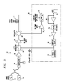
- the fixed input signals ⁇ 1 and ⁇ 2 are generated by first and second cw sources 12 and 14, respectively.
- the sources 12 and 14 are configured as diode lasers tuned to provide pulses at 1532.6 nm and 1536.15 nm, respectively (for a wavelength separation of 3.55 nm).
- the wavelengths provided are for exemplary purposes only, and, moreover, they may be generated by any suitable optical signal generating device, including an optical pulse generation. Because orthogonal polarizations have the potential to reduce the signal intensity by up to a factor of ten or more, care should be taken to see that the cw sources 12 and 14 are co-polarized to provide an adequate signal intensity.
- the cw signals output by optical sources 12 and 14 are combined and input to a phase modulator 16. While not required, the phase modulator advantageously serves to remove the annoying high-frequency ( ⁇ 1 MHz) modulation from the input signals that results from the finite temporal width of the exciting pulses.
- the output of the phase modulator is amplified by amplifier 18, and an accousto-optic modulator 20 coupled to a pulse generator 22 shapes the output of the cw sources into pulses at ⁇ 1 and ⁇ 2 .
- the output of the accousto-optic modulator 20 is supplied to an optical amplifier 24, an erbium doped fiber amplifier (EDFA) in the illustrative example, which amplifier provides sufficient gain to bring the pulse signals up to peak power levels near 1 W.
- EDFA erbium doped fiber amplifier
- a three-port optical circulator 26 launches the pulses into the fiber under test, indicated generally at F, and directs the Rayleigh backscattered signal to a tunable receiver arrangement 28.
- the receiver arrangement 28 comprises an EDFA pre-amplifier 30 which provides sufficient gain to allow subsequent processing of the backscattered signals.
- Tuning to the desired backscattered signal, which will at either the Stokes or anti-Stokes wavelength, is achieved by a tunable narrow band optical filter 32 which passes the signal of interest to a photodetector 34 for detection.
- Such an optical filter may be constructed, for example, by cascading a piezo-tuned Fabry-Perot etalon with a bandwidth of 20 Ghz and a free spectral range of 16 nm, with a tuneable, 1 nm bandwidth interference filter (neither of which are shown).
- the output of photodetector 34 is filtered by a bandpass filter 36, amplified by an amplifier 37, and supplied to a sampling oscilliscope 38.
- FIG. 4 shows samples of the signal retumed from a 34.4 km long, "dispersion tapered" span of fiber under test using the apparatus of FIG. 3.
- the high-intensity input end is at 0 km.
- An excellent signal-to-noise ratio can be observed, even at the far end of the span. This is due, in part, to the narrow effective bandwidth used to compute the noise referred to the input of the EDFA pre-amplifier 30 (FIG.
- FIG. 5 there are shown the nearly identical dispersion maps D(1557, z ) of the same dispersion tapered span discussed above, as inferred from (1) the Stokes signal, (2) the ant-Stokes signals, and (3) as translated to the common wavelength of 1557 nm.
- the dashed curve corresponds to the ideal exponential taper.
- Similar results were also obtained using a conventional destructive technique during which the fiber was cut into five sections.
- the results obtained in accordance with the present invention compare favorably to the results of the destructive examination, the latter being shown by the solid horizontal lines in FIG. 5.
- third order dispersion values were used, as determined from a comparison of the Stokes and anti-Stokes signals themselves. These third order dispersion values were not strictly constant across the span.
- the pump intensities at ⁇ 1 and ⁇ 2 were adjusted to be in a two-to-one ratio, respectively, for the measurement at ⁇ S , and in a one-to-two ratio for the measurement at ⁇ A .
- Eq. (9), supra no nonlinear contribution to the wave-vector mismatch should be discemible. This prediction was confirmed by noting a lack of any measurable change in the observed frequencies as the net pump power is reduced, so long as the two-to-one power ratios are maintained.
Landscapes
- Chemical & Material Sciences (AREA)
- Physics & Mathematics (AREA)
- Dispersion Chemistry (AREA)
- Optics & Photonics (AREA)
- Analytical Chemistry (AREA)
- General Physics & Mathematics (AREA)
- Optical Modulation, Optical Deflection, Nonlinear Optics, Optical Demodulation, Optical Logic Elements (AREA)
- Testing Of Optical Devices Or Fibers (AREA)
- Lasers (AREA)
- Optical Communication System (AREA)
- Light Guides In General And Applications Therefor (AREA)
Applications Claiming Priority (2)
| Application Number | Priority Date | Filing Date | Title |
|---|---|---|---|
| US08/682,229 US5956131A (en) | 1996-07-17 | 1996-07-17 | System and method for mapping chromatic dispersion in optical fibers |
| US682229 | 1996-07-17 |
Publications (3)
| Publication Number | Publication Date |
|---|---|
| EP0819926A2 true EP0819926A2 (de) | 1998-01-21 |
| EP0819926A3 EP0819926A3 (de) | 1999-03-31 |
| EP0819926B1 EP0819926B1 (de) | 2002-02-20 |
Family
ID=24738772
Family Applications (1)
| Application Number | Title | Priority Date | Filing Date |
|---|---|---|---|
| EP97304975A Expired - Lifetime EP0819926B1 (de) | 1996-07-17 | 1997-07-08 | System und Verfahren zur Erfassung von der chromatischen Dispersion in optischen Fasern |
Country Status (5)
| Country | Link |
|---|---|
| US (1) | US5956131A (de) |
| EP (1) | EP0819926B1 (de) |
| JP (1) | JP3376251B2 (de) |
| CA (1) | CA2206413A1 (de) |
| DE (1) | DE69710524T2 (de) |
Cited By (13)
| Publication number | Priority date | Publication date | Assignee | Title |
|---|---|---|---|---|
| EP1189367A1 (de) * | 2000-07-27 | 2002-03-20 | Alcatel | Verfahren und Vorrichtung zum Bestimmen einer wellenlängenabhängigen Information in einem optischen System |
| WO2002027292A1 (de) * | 2000-09-27 | 2002-04-04 | Siemens Aktiengesellschaft | Verfahren und vorrichtung zur messung der fasernichtlinearität einer lichtleitfaser in einer datenübertragungsstrecke |
| US6580500B2 (en) | 2001-02-22 | 2003-06-17 | Ando Electric Co., Ltd. | Chromatic dispersion distribution measurement apparatus and method for the same |
| US6580499B2 (en) | 2001-02-06 | 2003-06-17 | Ando Electric Co., Ltd. | Chromatic dispersion distribution measurement apparatus and method for the same |
| US6594005B2 (en) | 2001-02-02 | 2003-07-15 | Ando Electric Co., Ltd. | Chromatic dispersion distribution measurement apparatus, method and storage medium for the same |
| WO2003060456A1 (en) * | 2002-01-16 | 2003-07-24 | Agilent Technologies, Inc. | Otdr with concurrently applied stimulus signals |
| US6643603B2 (en) | 2001-02-07 | 2003-11-04 | Ando Electric Co., Ltd. | Chromatic dispersion distribution measurement apparatus and method for the same |
| EP1227309A3 (de) * | 2001-01-29 | 2004-01-21 | Ando Electric Co., Ltd. | Verfahren und Apparat zur Messung der Verteilung von chromatischen Dispersion |
| EP1236985A3 (de) * | 2001-03-02 | 2004-01-21 | Ando Electric Co., Ltd. | Apparat und Verfahren zur Messung der Verteilung von chromatischer Dispersion |
| EP1211499A3 (de) * | 2000-11-29 | 2004-01-28 | Ando Electric Co., Ltd. | Vorrichtung zur Messung der Farbstreuungsverteilung in optischen Fasern und dazugehöriges Messverfahren |
| EP1219945A3 (de) * | 2000-11-29 | 2004-01-28 | Ando Electric Co., Ltd. | Apparat und Verfahren zur Messung der chromatischen Dispersion in einer optischen Faser |
| US6882410B2 (en) | 2002-01-31 | 2005-04-19 | Ando Electric Co., Ltd. | Filter processing system for the output signal of optical time domain reflectometer in the chromatic dispersion distribution measurement apparatus |
| EP2202502A3 (de) * | 2008-12-25 | 2016-07-20 | Sumitomo Electric Industries, Ltd. | Vorrichtung und Verfahren zum Messen der chromatischen Dispersion |
Families Citing this family (20)
| Publication number | Priority date | Publication date | Assignee | Title |
|---|---|---|---|---|
| DE19808601A1 (de) * | 1998-02-28 | 1999-09-09 | Deutsche Telekom Ag | Messverfahren für Einzelfasern von Kabeln |
| US6650466B1 (en) * | 1999-08-27 | 2003-11-18 | Frank Wise | High-energy pulse compression using phase shifts produced by the cascade quadriatic nonlinearity |
| US6323950B1 (en) * | 1999-09-28 | 2001-11-27 | Lucent Technologies, Inc. | Chromatic dispersion measurement for optical components |
| KR100337132B1 (ko) * | 1999-10-15 | 2002-05-18 | 윤덕용 | 광 신호 대 잡음비를 측정하는 장치 및 방법 |
| JP4004720B2 (ja) * | 2000-08-09 | 2007-11-07 | 富士通株式会社 | 波長分散測定装置及びその方法 |
| US6462863B1 (en) * | 2001-07-11 | 2002-10-08 | Jds Uniphase Inc. | System and method for resolving polarization mode dispersion in optical fibers |
| US6654516B2 (en) * | 2001-08-20 | 2003-11-25 | Texas Instruments Incorporated | Optical system and method |
| JP2003130761A (ja) * | 2001-10-26 | 2003-05-08 | Ando Electric Co Ltd | 光ファイバの波長分散分布特性の測定方法及び測定装置 |
| WO2003042652A1 (en) * | 2001-11-13 | 2003-05-22 | Advantest Corporation | Wavelength dispersion probing system |
| US7667830B2 (en) * | 2004-05-13 | 2010-02-23 | The Boeing Company | Mixer-based time domain reflectometer and method |
| US7919325B2 (en) | 2004-05-24 | 2011-04-05 | Authentix, Inc. | Method and apparatus for monitoring liquid for the presence of an additive |
| US7221439B2 (en) * | 2005-04-29 | 2007-05-22 | Corning Incorporated | Method of estimating and measuring longitudinal dispersion in optical fibers |
| JP4463828B2 (ja) * | 2005-09-22 | 2010-05-19 | 日本電信電話株式会社 | 光導波路の波長分散の測定方法、測定装置及び測定プログラム |
| US20070171638A1 (en) * | 2006-01-24 | 2007-07-26 | Sbc Knowledge Ventures, L.P. | Apparatus and methods for transmitting light over optical fibers |
| US7787127B2 (en) * | 2007-10-15 | 2010-08-31 | Michael Galle | System and method to determine chromatic dispersion in short lengths of waveguides using a common path interferometer |
| JP5577592B2 (ja) * | 2008-12-25 | 2014-08-27 | 住友電気工業株式会社 | 波長分散測定装置及び波長分散測定方法 |
| JP5567126B2 (ja) * | 2010-10-18 | 2014-08-06 | 株式会社フジクラ | 波長分散測定装置及びそれを用いた波長分散測定方法 |
| US10545036B2 (en) * | 2016-11-22 | 2020-01-28 | Baker Hughes, A Ge Company, Llc | Distributed parameter measurements using multiple optical sources |
| US10211920B1 (en) * | 2017-09-07 | 2019-02-19 | Amazon Technologies, Inc. | Latency based chromatic dispersion estimation methods |
| US12050150B2 (en) * | 2021-06-04 | 2024-07-30 | Exfo Inc. | Spectral averaging of OTDR traces |
Family Cites Families (2)
| Publication number | Priority date | Publication date | Assignee | Title |
|---|---|---|---|---|
| JPH079386B2 (ja) * | 1988-05-18 | 1995-02-01 | 国際電信電話株式会社 | 光ファイバ分散特性測定方式 |
| US4994675A (en) * | 1989-04-28 | 1991-02-19 | Rebo Research, Inc. | Method and apparatus for checking continuity of optic transmission |
-
1996
- 1996-07-17 US US08/682,229 patent/US5956131A/en not_active Expired - Lifetime
-
1997
- 1997-05-28 CA CA002206413A patent/CA2206413A1/en not_active Abandoned
- 1997-07-08 EP EP97304975A patent/EP0819926B1/de not_active Expired - Lifetime
- 1997-07-08 DE DE69710524T patent/DE69710524T2/de not_active Expired - Fee Related
- 1997-07-16 JP JP19166097A patent/JP3376251B2/ja not_active Expired - Fee Related
Non-Patent Citations (3)
| Title |
|---|
| MAMSYSHEV P V ET AL: "PSEUDO-PHASE-MATCHED FOUR-WAVE MIXING IN SOLITON WAVELENGTH- DIVISION MULTIPLEXING TRANSMISSION" OPTICS LETTERS, vol. 21, no. 6, 15 March 1996, pages 396-398, XP000587033 * |
| NISHI S ET AL: "TECHNIQUE FOR MEASURING THE DISTRIBUTED ZERO DISPERSION WAVELENGTH OF OPTICAL FIBRES USING IDLER PULSE GENERATION CAUSED BY MODULATIONINSTABILITY" ELECTRONICS LETTERS, vol. 32, no. 6, 14 March 1996, pages 579-581, XP000593648 * |
| SHIBATA N ET AL: "PHASE-MISMATCH DEPENDENCE OF EFFICIENCY OF WAVE GENERATION THROUGH FOUR-WAVE MIXING IN A SINGLE-MODE OPTICAL FIBER" IEEE JOURNAL OF QUANTUM ELECTRONICS, vol. 23, no. 7, July 1987, pages 1205-1210, XP000616790 * |
Cited By (17)
| Publication number | Priority date | Publication date | Assignee | Title |
|---|---|---|---|---|
| EP1189367A1 (de) * | 2000-07-27 | 2002-03-20 | Alcatel | Verfahren und Vorrichtung zum Bestimmen einer wellenlängenabhängigen Information in einem optischen System |
| WO2002027292A1 (de) * | 2000-09-27 | 2002-04-04 | Siemens Aktiengesellschaft | Verfahren und vorrichtung zur messung der fasernichtlinearität einer lichtleitfaser in einer datenübertragungsstrecke |
| US7057713B2 (en) | 2000-09-27 | 2006-06-06 | Siemens Aktiengesellschaft | Method and device for measuring the fiber non-linearity of an optical fiber in a data transmission path |
| EP1219945A3 (de) * | 2000-11-29 | 2004-01-28 | Ando Electric Co., Ltd. | Apparat und Verfahren zur Messung der chromatischen Dispersion in einer optischen Faser |
| EP1211499A3 (de) * | 2000-11-29 | 2004-01-28 | Ando Electric Co., Ltd. | Vorrichtung zur Messung der Farbstreuungsverteilung in optischen Fasern und dazugehöriges Messverfahren |
| EP1227309A3 (de) * | 2001-01-29 | 2004-01-21 | Ando Electric Co., Ltd. | Verfahren und Apparat zur Messung der Verteilung von chromatischen Dispersion |
| EP1229318A3 (de) * | 2001-02-02 | 2004-01-28 | Ando Electric Co., Ltd. | Verfahren und Apparat zur Messung der chromatischen Dispersionsverteilung und zugehöriges Speichermedium |
| US6594005B2 (en) | 2001-02-02 | 2003-07-15 | Ando Electric Co., Ltd. | Chromatic dispersion distribution measurement apparatus, method and storage medium for the same |
| US6580499B2 (en) | 2001-02-06 | 2003-06-17 | Ando Electric Co., Ltd. | Chromatic dispersion distribution measurement apparatus and method for the same |
| EP1236984A3 (de) * | 2001-02-06 | 2004-01-21 | Ando Electric Co., Ltd. | Vorrichtung und Verfahren zur Messung der chromatischen Dispersionsverteilung |
| US6643603B2 (en) | 2001-02-07 | 2003-11-04 | Ando Electric Co., Ltd. | Chromatic dispersion distribution measurement apparatus and method for the same |
| EP1235064A3 (de) * | 2001-02-22 | 2004-01-28 | Ando Electric Co., Ltd. | Verfahren und Apparat zur Messung der Verteilung der chromatischen Dispersion |
| US6580500B2 (en) | 2001-02-22 | 2003-06-17 | Ando Electric Co., Ltd. | Chromatic dispersion distribution measurement apparatus and method for the same |
| EP1236985A3 (de) * | 2001-03-02 | 2004-01-21 | Ando Electric Co., Ltd. | Apparat und Verfahren zur Messung der Verteilung von chromatischer Dispersion |
| WO2003060456A1 (en) * | 2002-01-16 | 2003-07-24 | Agilent Technologies, Inc. | Otdr with concurrently applied stimulus signals |
| US6882410B2 (en) | 2002-01-31 | 2005-04-19 | Ando Electric Co., Ltd. | Filter processing system for the output signal of optical time domain reflectometer in the chromatic dispersion distribution measurement apparatus |
| EP2202502A3 (de) * | 2008-12-25 | 2016-07-20 | Sumitomo Electric Industries, Ltd. | Vorrichtung und Verfahren zum Messen der chromatischen Dispersion |
Also Published As
| Publication number | Publication date |
|---|---|
| DE69710524T2 (de) | 2002-09-12 |
| JPH1083006A (ja) | 1998-03-31 |
| US5956131A (en) | 1999-09-21 |
| JP3376251B2 (ja) | 2003-02-10 |
| DE69710524D1 (de) | 2002-03-28 |
| CA2206413A1 (en) | 1998-01-17 |
| EP0819926B1 (de) | 2002-02-20 |
| EP0819926A3 (de) | 1999-03-31 |
Similar Documents
| Publication | Publication Date | Title |
|---|---|---|
| EP0819926B1 (de) | System und Verfahren zur Erfassung von der chromatischen Dispersion in optischen Fasern | |
| US7869014B2 (en) | System for measuring the wavelength dispersion and nonlinear coefficient of an optical fiber | |
| Mollenauer et al. | Method for facile and accurate measurement of optical fiber dispersion maps | |
| Prigent et al. | Measurement of fiber nonlinear Kerr coefficient by four-wave mixing | |
| US5724126A (en) | Method for measuring distribution of zero dispersion wavelengths in an optical fiber and apparatus therefor | |
| Fatome et al. | Measurement of nonlinear and chromatic dispersion parameters of optical fibers using modulation instability | |
| US6118523A (en) | High-resolution zero-dispersion wavelength mapping in single mode fiber | |
| US6462863B1 (en) | System and method for resolving polarization mode dispersion in optical fibers | |
| US6067149A (en) | Dispersion-map measurements of optical fibers | |
| US6801308B2 (en) | Method and apparatus for measuring chromatic dispersion in optical fibers | |
| Barry et al. | Simultaneous measurement of optical fibre nonlinearity and dispersion using frequency resolved optical gating | |
| US6580499B2 (en) | Chromatic dispersion distribution measurement apparatus and method for the same | |
| Hotate | A correlation-based continuous-wave technique for measuring Brillouin gain spectrum distribution along an optical fiber with centimeter-order spatial resolution | |
| EP1927838B1 (de) | Verfahren, vorrichtung und programm zur messung der wellenlängendispersion eines optischen wellenleiters | |
| JP4690690B2 (ja) | 光ファイバの波長分散値及び非線形定数の測定方法、光ファイバの波長分散値及び非線形定数の測定装置、ファイバ製造方法、分散分布測定方法、測定誤差補償方法、測定条件特定方法 | |
| US8102519B2 (en) | System and method for measuring dispersion | |
| Suetsugu et al. | Measurement of zero-dispersion wavelength variation in concatenated dispersion-shifted fibers by improved four-wave-mixing technique | |
| Philen | Measurement of the Non-Linear Index of Refraction, N2 | |
| JP3291158B2 (ja) | 光ファイバの非線形屈折率の測定方法およびその装置 | |
| US7298465B2 (en) | Measurement and characterization of nonlinear phase shifts | |
| González-Herráez et al. | Simultaneous position-resolved mapping of chromatic dispersion and Brillouin shift along single-mode optical fibers | |
| Rai et al. | 2000 Fibre Bragg Gratings Interrogated with Correlation-Aided Optical Time Domain Reflectometry with Direct Detection | |
| MXPA97005348A (en) | System and method for the correlation of the cromatic dispersion in optimal fibers | |
| JP3259437B2 (ja) | 光ファイバパラメータの長手方向分布測定装置 | |
| Dudley et al. | Intermodal dispersion and polarization mode dispersion measurements in optical fibers using a self-modelocked Ti: sapphire laser |
Legal Events
| Date | Code | Title | Description |
|---|---|---|---|
| PUAI | Public reference made under article 153(3) epc to a published international application that has entered the european phase |
Free format text: ORIGINAL CODE: 0009012 |
|
| AK | Designated contracting states |
Kind code of ref document: A2 Designated state(s): DE FR GB |
|
| PUAL | Search report despatched |
Free format text: ORIGINAL CODE: 0009013 |
|
| AK | Designated contracting states |
Kind code of ref document: A3 Designated state(s): AT BE CH DE DK ES FI FR GB GR IE IT LI LU MC NL PT SE |
|
| 17P | Request for examination filed |
Effective date: 19990916 |
|
| AKX | Designation fees paid |
Free format text: DE FR GB |
|
| GRAG | Despatch of communication of intention to grant |
Free format text: ORIGINAL CODE: EPIDOS AGRA |
|
| 17Q | First examination report despatched |
Effective date: 20010504 |
|
| GRAG | Despatch of communication of intention to grant |
Free format text: ORIGINAL CODE: EPIDOS AGRA |
|
| GRAH | Despatch of communication of intention to grant a patent |
Free format text: ORIGINAL CODE: EPIDOS IGRA |
|
| GRAH | Despatch of communication of intention to grant a patent |
Free format text: ORIGINAL CODE: EPIDOS IGRA |
|
| REG | Reference to a national code |
Ref country code: GB Ref legal event code: IF02 |
|
| GRAA | (expected) grant |
Free format text: ORIGINAL CODE: 0009210 |
|
| AK | Designated contracting states |
Kind code of ref document: B1 Designated state(s): DE FR GB |
|
| REF | Corresponds to: |
Ref document number: 69710524 Country of ref document: DE Date of ref document: 20020328 |
|
| ET | Fr: translation filed | ||
| PLBE | No opposition filed within time limit |
Free format text: ORIGINAL CODE: 0009261 |
|
| STAA | Information on the status of an ep patent application or granted ep patent |
Free format text: STATUS: NO OPPOSITION FILED WITHIN TIME LIMIT |
|
| 26N | No opposition filed |
Effective date: 20021121 |
|
| PGFP | Annual fee paid to national office [announced via postgrant information from national office to epo] |
Ref country code: GB Payment date: 20040825 Year of fee payment: 8 |
|
| PGFP | Annual fee paid to national office [announced via postgrant information from national office to epo] |
Ref country code: FR Payment date: 20040831 Year of fee payment: 8 |
|
| PGFP | Annual fee paid to national office [announced via postgrant information from national office to epo] |
Ref country code: DE Payment date: 20040917 Year of fee payment: 8 |
|
| PG25 | Lapsed in a contracting state [announced via postgrant information from national office to epo] |
Ref country code: GB Free format text: LAPSE BECAUSE OF NON-PAYMENT OF DUE FEES Effective date: 20050708 |
|
| PG25 | Lapsed in a contracting state [announced via postgrant information from national office to epo] |
Ref country code: DE Free format text: LAPSE BECAUSE OF NON-PAYMENT OF DUE FEES Effective date: 20060201 |
|
| GBPC | Gb: european patent ceased through non-payment of renewal fee |
Effective date: 20050708 |
|
| PG25 | Lapsed in a contracting state [announced via postgrant information from national office to epo] |
Ref country code: FR Free format text: LAPSE BECAUSE OF NON-PAYMENT OF DUE FEES Effective date: 20060331 |
|
| REG | Reference to a national code |
Ref country code: FR Ref legal event code: ST Effective date: 20060331 |