EP0819965A1 - Méthode et appareil pour enregistrer une information d'images - Google Patents
Méthode et appareil pour enregistrer une information d'images Download PDFInfo
- Publication number
- EP0819965A1 EP0819965A1 EP97111492A EP97111492A EP0819965A1 EP 0819965 A1 EP0819965 A1 EP 0819965A1 EP 97111492 A EP97111492 A EP 97111492A EP 97111492 A EP97111492 A EP 97111492A EP 0819965 A1 EP0819965 A1 EP 0819965A1
- Authority
- EP
- European Patent Office
- Prior art keywords
- light
- mirror
- light guide
- emitted
- section
- Prior art date
- Legal status (The legal status is an assumption and is not a legal conclusion. Google has not performed a legal analysis and makes no representation as to the accuracy of the status listed.)
- Granted
Links
- 238000000034 method Methods 0.000 title claims description 6
- OAICVXFJPJFONN-UHFFFAOYSA-N Phosphorus Chemical compound [P] OAICVXFJPJFONN-UHFFFAOYSA-N 0.000 claims description 42
- 230000005855 radiation Effects 0.000 claims description 17
- 239000013307 optical fiber Substances 0.000 claims description 12
- 230000004936 stimulating effect Effects 0.000 claims description 3
- 239000011247 coating layer Substances 0.000 claims description 2
- 229910000679 solder Inorganic materials 0.000 claims 1
- 239000004020 conductor Substances 0.000 abstract 4
- 239000000835 fiber Substances 0.000 description 47
- 239000011888 foil Substances 0.000 description 8
- 230000008878 coupling Effects 0.000 description 7
- 238000010168 coupling process Methods 0.000 description 7
- 238000005859 coupling reaction Methods 0.000 description 7
- 239000004065 semiconductor Substances 0.000 description 3
- 230000000638 stimulation Effects 0.000 description 3
- 230000003287 optical effect Effects 0.000 description 2
- 241001479434 Agfa Species 0.000 description 1
- 239000011258 core-shell material Substances 0.000 description 1
- 238000011156 evaluation Methods 0.000 description 1
- 238000002474 experimental method Methods 0.000 description 1
- 230000002349 favourable effect Effects 0.000 description 1
- 239000011521 glass Substances 0.000 description 1
- 238000004519 manufacturing process Methods 0.000 description 1
- 239000002184 metal Substances 0.000 description 1
- 238000012986 modification Methods 0.000 description 1
- 230000004048 modification Effects 0.000 description 1
- 238000012545 processing Methods 0.000 description 1
- 238000002601 radiography Methods 0.000 description 1
- 239000004753 textile Substances 0.000 description 1
- 238000012546 transfer Methods 0.000 description 1
Images
Classifications
-
- H—ELECTRICITY
- H04—ELECTRIC COMMUNICATION TECHNIQUE
- H04N—PICTORIAL COMMUNICATION, e.g. TELEVISION
- H04N1/00—Scanning, transmission or reproduction of documents or the like, e.g. facsimile transmission; Details thereof
- H04N1/024—Details of scanning heads ; Means for illuminating the original
- H04N1/028—Details of scanning heads ; Means for illuminating the original for picture information pick-up
- H04N1/02815—Means for illuminating the original, not specific to a particular type of pick-up head
- H04N1/0282—Using a single or a few point light sources, e.g. a laser diode
- H04N1/0283—Using a single or a few point light sources, e.g. a laser diode in combination with a light deflecting element, e.g. a rotating mirror
-
- G—PHYSICS
- G03—PHOTOGRAPHY; CINEMATOGRAPHY; ANALOGOUS TECHNIQUES USING WAVES OTHER THAN OPTICAL WAVES; ELECTROGRAPHY; HOLOGRAPHY
- G03B—APPARATUS OR ARRANGEMENTS FOR TAKING PHOTOGRAPHS OR FOR PROJECTING OR VIEWING THEM; APPARATUS OR ARRANGEMENTS EMPLOYING ANALOGOUS TECHNIQUES USING WAVES OTHER THAN OPTICAL WAVES; ACCESSORIES THEREFOR
- G03B42/00—Obtaining records using waves other than optical waves; Visualisation of such records by using optical means
- G03B42/08—Visualisation of records by optical means
-
- H—ELECTRICITY
- H04—ELECTRIC COMMUNICATION TECHNIQUE
- H04N—PICTORIAL COMMUNICATION, e.g. TELEVISION
- H04N1/00—Scanning, transmission or reproduction of documents or the like, e.g. facsimile transmission; Details thereof
- H04N1/024—Details of scanning heads ; Means for illuminating the original
- H04N1/028—Details of scanning heads ; Means for illuminating the original for picture information pick-up
- H04N1/0281—Details of scanning heads ; Means for illuminating the original for picture information pick-up with means for collecting light from a line or an area of the original and for guiding it to only one or a relatively low number of picture element detectors
-
- G—PHYSICS
- G02—OPTICS
- G02B—OPTICAL ELEMENTS, SYSTEMS OR APPARATUS
- G02B6/00—Light guides; Structural details of arrangements comprising light guides and other optical elements, e.g. couplings
- G02B6/04—Light guides; Structural details of arrangements comprising light guides and other optical elements, e.g. couplings formed by bundles of fibres
Definitions
- the invention relates to a method and a device for receiving Light according to the preamble of claim 1.
- Devices of this type are required for image information relating to a stimulable fluorescent plate.
- stimulable phosphor foils instead conventional X-ray sheet films used.
- the phosphor foils have opposite conventional X-ray films have the advantage of an almost linear reproduction characteristic. The image quality that can be achieved is therefore far less sensitive compared to too low or too high dose rates during production of the x-ray image.
- Another advantage of stimulable phosphor foils is that they are reusable. After an x-ray or after reading the image information and saving it in electronic Media deleted and used for further X-rays.
- phosphor foils Another advantage of using phosphor foils is that they are: their mechanical handling largely the conventional X-ray sheet films are similar. Existing loading and unloading devices for X-ray sheet film facilities X-ray sheet film cassettes are therefore largely can also be used for phosphor foils.
- a method and an apparatus for handling such phosphor-coated Foils is e.g. B. known from DE 37 31 203 A1.
- the phosphor sheet is initially loaded into an X-ray cassette. Then in data relevant to admission such as patient name, date of birth, treating doctor etc. in a semiconductor memory located on the cassette written. Then the X-ray is taken. To capture The X-ray image is inserted into a digital reader. There the cassette is opened, the phosphor film is removed and the Film stimulated with a scanner. This from the phosphor film emitted light is received by a light collecting device and in rasterized, digital image signals converted. These signals can then be in one digital image processing device can be processed further.
- the present invention relates to the scanning part of the entry mentioned device.
- scanning the image information from the phosphor sheet does it come u. a. depends on as much of the radiation energy as possible in the phosphor sheet is included.
- the stimulation of the phosphor foil takes place in usually by a laser beam. It stimulates and stimulates the phosphor film in that the stored X-ray energy through low-energy radiation, preferably visible light of a certain wavelength from which Phosphor film emerges.
- DE-OS 29 51 501 is a radiation image reading device become known, the radiation energy from a stimulable Phosphor plate and leads to a radiation detector.
- a disadvantage of this arrangement is that those rays emitted by the stimulable Fluorescent plate escape almost vertically, not or only under penetrate the light guide arrangement at a very steep entry angle. This causes these beams to be coupled in very poorly when the light guide arrangement consists of light fibers.
- the light entry area is a light guide arrangement with which the light is guided from the medium to be scanned to the photodetector
- the mirror is arranged so that it is in relation to a laser beam which is the medium illuminated, located on the side of the light guide arrangement. This leaves the light coming from the medium is optimally coupled into the light guide arrangement.
- Coupling angle, d. H. those that are substantially perpendicular to the entrance surface of the fibers are standing and therefore smaller than the acceptance angle of the light fibers are achieve.
- the acceptance angle is the largest allowable angle for the incident radiation is passed on in the fiber.
- the light guide arrangement can be arranged by the arrangement according to the invention arrange with respect to the medium to be scanned such that the Entry surface of the light guide arrangement opposite the plane in which the medium lies, has a relatively small angle of inclination.
- the light guide arrangement is arranged in the immediate vicinity of the scanning laser beam. Thereby those rays of the medium to be scanned that are close of the incoming laser beam are emitted, to a large extent in the Couple in the light guide arrangement.
- This arrangement is particularly advantageous when scanning stimulable phosphor panels because of their spatial radiation characteristics is essentially a so-called Lambert radiator characteristic, that the greatest beam intensity in the vertical direction from the light emitting Level is emitted.
- the mirror is on the Light guide arrangement attached. This allows the adjustment of the mirror arrangement significantly easier relative to the light guide arrangement because relative movements, hardly possible, in particular when the reading device is shaken are.
- the mirror arrangement is such that those coupled into the light guide arrangement Rays have an entry angle that is at most as large as that maximum coupling or acceptance angle predetermined by the light fibers of the light guide arrangement. This is typically around 30 °.
- the surface of the mirror arrangement has a curvature profile through which rays emitted laterally from the medium are reflected so that they are as possible steep, essentially vertical, impinge on the light guide arrangement.
- the mirror surface is preferably coated in such a way that it is suitable for the wavelength of the emitted rays results in a particularly high reflection coefficient.
- the light guide arrangements on both sides attached with mirrors attached. It is particularly advantageous the light fibers of the two light guide arrangements in the area of the light-detecting Elements (photomultiplier) merge, the shape of the merged end piece to the shape of the light-collecting Elements is adjusted.
- the end face of the two merged light guide elements and the area of the photomultiplier one circle each. However, other shapes such as a rectangular shape are also possible.
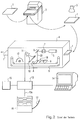
- An x-ray cassette 1 is with a stimulable image plate, especially a phosphor film. She will be in an identification station 2 is introduced, in which the data relevant to the exposure are semiconductor memory located in the cassette can be written. Over a Input console is various data such as patient name, admission area, treating doctor etc., can be entered. It can be provided a digital Read patient data card and the data directly to the semiconductor memory of the Transfer cassette. You can also choose from certain selection menus desired evaluation parameters for the phosphor film can be defined. After The identification of the cassette is the x-ray under an x-ray tube 3 created. The phosphor film carries the X-ray image as a latent image.
- the X-ray cassette 1 is read out of this latent image in a digital scanning device 4 entered. There opens a mechanical not shown Set up the X-ray cassette 1 and remove the phosphor film 8. Via a The phosphor device is then transported to a reading station 18 fed.
- the reading station 18 comprises a laser 5, a movable mirror 6, a lens 7, a light guide arrangement 10 and one Photomultiplier 11.
- the laser 5 emits a light beam 25 with which the stimulable phosphor sheet 8 can be excited.
- the wavelength of the light beam 25 can be in the infrared, red or green wavelength range, depending on what type of phosphor film is present.
- the light is on the lens 7 on the Focused on phosphor sheet 8.
- the movable mirror 6 (oscillating mirror or rotating polygon mirror) direct the laser radiation in direction B point and line by line on the phosphor film 8.
- stimulation light is emitted from the phosphor film 8.
- This light is collected by the light guides 10 and to the photomultiplier 11 emitted, which amplifies the signals.
- the Digitized signals and forwarded to a computer 13 with image memory.
- the signals can additionally filter stages according to methods known per se run through like an anti-aliasing filter and / or electronically compressed will.
- the phosphor sheet 8 is removed from a conveyor belt 9 transported in a slow scan direction A.
- the phosphor film 8 After the phosphor film 8 has been scanned, it is removed by an erasing device 12 deleted. Then the X-ray cassette 1 is again with the same Load phosphor sheet 8 and is available for the next X-ray Available.
- the digitized image can be stored in a digital memory 15 by the computer 13, evaluable on a diagnostic screen 14 or via a digital Interface 13a can be output to a hardcopy device 16 which prints the image reproduced on photographic film 17. These are via the interface 13a Image data can also be forwarded to any other digital image system.
- Fig. 3 shows details of a light guide arrangement, such as in the System Agfa Diagnostic Center (ADC 70) sold by the applicant is.
- ADC 70 System Agfa Diagnostic Center
- the figure shows the laser beam 25, which at point 19 on the stimulable phosphor film 8 hits.
- the light stimulated by the laser beam 25 is according to one Lambertian radiation distribution in those above the phosphor sheet 8 Room radiated.
- Light beams 50 stimulated in this way are emitted by the light guide arrangement 10 added. It has a large number of optical fibers 21 which are held in a fiber module 33.
- the stimulated light rays 50 hit the center of the fiber module 33 in substantially perpendicular to the end faces of the optical fibers 21 while in the edge areas of the fiber module at a relatively flat angle in the Fibers are coupled.
- the one coupled into the light guide arrangement 10 The proportion of light is therefore lower in the edge region of the fiber module 33 than in FIG its center.
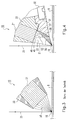
- Fig. 4 shows a first embodiment of the invention.
- a laser beam 25 in turn stimulates the impact point 90 of a phosphor plate 8 therein stored energy.
- Light rays 50 emerge from the point of impact 90 Phosphor film 8. Some of the stimulated rays enter directly into the Entry surface 49 of the light guide arrangement 10, i. H. into the light fibers 21.
- the Light fibers 21 are built up in a core-shell structure and have typical Acceptance angle of about 30 ° around the perpendicular to the entrance surface 49. They are made of plastic, but could just as well be made of glass. Your fiber ends 48 are cut substantially flat and perpendicular to their longitudinal direction or ground.
- the fibers 21 are ordered, i. H.
- a mirror block 31 is attached to the fiber module 33, the mirror surface 30 thereof is highly reflective for light of the wavelength that the image plate 8 as emits stimulated light.
- This light can e.g. B. be green or blue or in a wavelength range outside visible light, e.g. B. in UV range.
- the wavelength of the laser beam 25 is adapted to the image plate 8 and lies in the visible wavelength range, e.g. B. at 633 nm, or in Infrared range.
- the stimulated light typically has a shorter one Wavelength as the stimulating light.
- the mirror surface 30 can be provided with an optical coating layer 37 so that it reflects the stimulated light better than the stimulating light of the laser beam 25.
- the mirror block 31 is attached, for example, with screws 32 attached to the optical fiber module.
- the mirror surface 30 can be flat. in the shown embodiment, however, it is curved. This can be the advantage achieved that the light in the light entry region 22 of the light guide arrangement is optimally coupled into the optical fibers 21.
- the mirror surface 30 can be shaped accordingly so that all in the light entry area 22 of the light guide assembly 10 located so steep on the Fiber ends 48 meet the total reflection condition within the fiber the fiber. Experiments have shown that with the arrangement according to FIG. 4 in comparison to an arrangement according to FIG. 3 at the exit of the light fibers significantly more fibers are light, d. H. that at the entrance more light in the Fibers can be coupled, so more light is the condition of the Total reflection inside the fiber fulfilled.
- the structure according to FIG. 4 can also achieve the steepest slope beam 51 which is reflected away from the image plate 8 and which is still in the optical fibers 21 is coupled, is coupled essentially vertically.
- This ray 51 is due to the Lambertian radiation characteristic of the stimulated radiation the brightest. Due to the essentially vertical coupling into the Optical fibers it is optimal, d. H. with minimal losses, to the output side End of the light fibers.
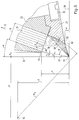
- FIG. 5 shows geometric details of the light guide arrangement according to FIG. 4.
- the plane is designated in which the surface of the image plate 8 lies.
- 54 denotes the perpendicular to plane 59, which passes through pixel 19.
- the distance f of the edge 53 from the image plate 59 is 6.5 mm.
- the Width b of the light fibers 21 is 4.0 mm.
- the fibers are along the direction C arranged in the fiber module 33 parallel to each other. You are opposite the center perpendicular 54 by an angle ⁇ in the range between 10 and 30 °, preferably inclined by 20 °.
- the curvature of the mirror surface 30 is in the shape of the entry surface 59 adapted to the fiber arrangement 21.
- a cylindrical mirror surface 30 has been selected.
- elliptical or other curved surfaces can also be advantageous. They result from the optical boundary conditions.
- An optimal one Curvature surface can, for example, by interpolation of the ideal reflection points be generated on an ideal reflection surface.
- Figure 5 shows that the coupling angle into the optical fiber arrangement 21 of those beams 56, 57 and 58, which strike in edge areas of the entry surface 49, always are still so large that sufficient total reflection within the fibers 21 for guiding the light is guaranteed.
- the coupling angles ⁇ , ⁇ and ⁇ for the Beams 57, 56 and 58 are 9.5 °, 25.4 ° and 24.7 °, i.e. H. they are all below the maximum fiber coupling angle of 30 °.
- the whole, with the fiber arrangement coupling angle ⁇ is 71.6 °.
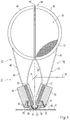
- FIG. 1 shows a further improved embodiment of a light guide arrangement 10. It is based on the fact that two of the same kind, arranged in mirror-image relation to each other Light-guiding elements are mirror-symmetrical to the scanning laser beam 25 are arranged.
- the laser beam 25 divides the space above the image plate 8 into two half-spaces 26 and 27.
- the dividing line 28 divides the two half-spaces 26, 27.
- a fiber module 33 is arranged in the first half space 26, in the second half space 27 a fiber module 34. Both fiber modules can according to the embodiment 4 may be configured.
- the fiber modules are in the range of incident laser beam 25 shaped so that it just barely on the image plate 8 can hit without reflecting on one of the two fiber modules. Stimulations are in turn stimulated from the surface 20 of the phosphor film 8 Light rays emitted into the space above the phosphor sheet 8.
- the fiber module 34 has light fibers 35, which Light from the light entry area 36 via a light guide area 42 lead a light exit area 24 of the light guide assembly 10.
- the fiber module 33 also merges into a light guide area 23, which is at the light exit area 24 ends.
- the fiber module 34 also has a mirror 38 on a mirror block 39. This mirror block 39 is included, for example Screws 40 attached to the fiber module 34.
- the fibers 21 and 35 are each loosely guided. You are in this embodiment covered with light-tight textile covers 41 and 43.
- the light fibers 21, 35 are embedded in a holder 44.
- the fibers of the two modules 33 and 34 are each in a semicircular shape Metal frame 40 or 46 embedded. They are on a butt edge 47 laid together.
- the entire light guide arrangement 10 thus has a circular shape Exit cross section. He is at the light entry window of the photomultiplier 11 adapted, the shape of which is also circular.
Landscapes
- Physics & Mathematics (AREA)
- Engineering & Computer Science (AREA)
- Multimedia (AREA)
- Signal Processing (AREA)
- Optics & Photonics (AREA)
- General Physics & Mathematics (AREA)
- Facsimile Scanning Arrangements (AREA)
- Radiography Using Non-Light Waves (AREA)
Applications Claiming Priority (2)
| Application Number | Priority Date | Filing Date | Title |
|---|---|---|---|
| DE19629299A DE19629299A1 (de) | 1996-07-20 | 1996-07-20 | Verfahren und Vorrichtung zum Aufnehmen einer Bildinformation |
| DE19629299 | 1996-07-20 |
Publications (2)
| Publication Number | Publication Date |
|---|---|
| EP0819965A1 true EP0819965A1 (fr) | 1998-01-21 |
| EP0819965B1 EP0819965B1 (fr) | 2001-10-17 |
Family
ID=7800345
Family Applications (1)
| Application Number | Title | Priority Date | Filing Date |
|---|---|---|---|
| EP97111492A Expired - Lifetime EP0819965B1 (fr) | 1996-07-20 | 1997-07-08 | Méthode et appareil pour enregistrer une information d'images |
Country Status (3)
| Country | Link |
|---|---|
| US (1) | US5898184A (fr) |
| EP (1) | EP0819965B1 (fr) |
| DE (2) | DE19629299A1 (fr) |
Cited By (1)
| Publication number | Priority date | Publication date | Assignee | Title |
|---|---|---|---|---|
| US9916722B2 (en) | 2009-12-03 | 2018-03-13 | Patent Investment & Licensing Company | Gaming device having advance game information analyzer |
Families Citing this family (6)
| Publication number | Priority date | Publication date | Assignee | Title |
|---|---|---|---|---|
| US6555838B1 (en) * | 2000-06-29 | 2003-04-29 | Essex Electro Engineering, Inc. | Method and apparatus for radiographic imaging |
| US6800870B2 (en) * | 2000-12-20 | 2004-10-05 | Michel Sayag | Light stimulating and collecting methods and apparatus for storage-phosphor image plates |
| EP1612582B1 (fr) * | 2004-06-29 | 2009-09-09 | Agfa-Gevaert HealthCare GmbH | Dispositif et méthode pour la lecture d'information d'image à partir d'une couche de phosphore |
| DE502004002961D1 (de) * | 2004-06-29 | 2007-04-05 | Agfa Gevaert Healthcare Gmbh | Vorrichtung und Verfahren zum Auslesen von in einer Speicherphosphorschicht gespeicherten Röntgeninformationen |
| DE102005038999A1 (de) * | 2005-08-16 | 2007-03-01 | Schott Ag | Strahlformungseinrichtung eines optischen Systems, insbesondere eines optischen Signalaufnehmers und optisches System, insbesondere optischer Signalaufnehmer mit Strahlformungseinrichtung |
| DE502005007861D1 (de) * | 2005-12-29 | 2009-09-17 | Agfa Gevaert Healthcare Gmbh | Antriebsvorrichtung für eine optische Abtasteinrichtung |
Citations (4)
| Publication number | Priority date | Publication date | Assignee | Title |
|---|---|---|---|---|
| DE2951501A1 (de) * | 1978-12-26 | 1980-07-17 | Fuji Photo Film Co Ltd | Strahlungsbildlesevorrichtung |
| US4736102A (en) * | 1985-07-29 | 1988-04-05 | Minnesota Mining And Manufacturing Company | Reading device for stimulable phosphor panel |
| US4818861A (en) * | 1986-06-25 | 1989-04-04 | Hitachi Medical Corp. | Film image reading out device |
| JPH02254408A (ja) * | 1989-03-29 | 1990-10-15 | Fuji Photo Film Co Ltd | 画像読取装置 |
Family Cites Families (8)
| Publication number | Priority date | Publication date | Assignee | Title |
|---|---|---|---|---|
| US4485302A (en) * | 1978-12-26 | 1984-11-27 | Fuji Photo Film Co., Ltd. | Radiation image read out device |
| EP0144856B1 (fr) * | 1983-04-01 | 1989-03-01 | Fuji Photo Film Co., Ltd. | Dispositif pour la reproduction d'image de rayonnement |
| JPS6411256A (en) * | 1987-07-03 | 1989-01-13 | Toshiba Corp | Radiograph reader |
| DE3731203A1 (de) * | 1987-09-17 | 1989-03-30 | Agfa Gevaert Ag | Verfahren zur handhabung von roentgenaufnahmekassetten mit einer phosphorbeschichteten folie und zur durchfuehrung des verfahrens geeignete lesestation |
| JPH0678908A (ja) * | 1992-09-03 | 1994-03-22 | Fujitsu Ltd | 放射線画像読取装置 |
| JPH07128759A (ja) * | 1993-11-05 | 1995-05-19 | Fuji Photo Film Co Ltd | 放射線画像読取方法および装置 |
| DE29510683U1 (de) * | 1995-07-09 | 1995-08-31 | Thoms, Michael, Dr., 91058 Erlangen | Einrichtung zum Lesen von Bildinformationen einer Bildvorlage |
| ES2289159T3 (es) * | 2001-11-14 | 2008-02-01 | Ortho-Mcneil Pharmaceutical Corporation | Derivados tetraciclicos sustituidos de pirroloquinolona utilizados como inhibidores de fosfodiesterasa. |
-
1996
- 1996-07-20 DE DE19629299A patent/DE19629299A1/de not_active Withdrawn
-
1997
- 1997-07-08 DE DE59704937T patent/DE59704937D1/de not_active Expired - Fee Related
- 1997-07-08 EP EP97111492A patent/EP0819965B1/fr not_active Expired - Lifetime
- 1997-07-16 US US08/895,196 patent/US5898184A/en not_active Expired - Fee Related
Patent Citations (4)
| Publication number | Priority date | Publication date | Assignee | Title |
|---|---|---|---|---|
| DE2951501A1 (de) * | 1978-12-26 | 1980-07-17 | Fuji Photo Film Co Ltd | Strahlungsbildlesevorrichtung |
| US4736102A (en) * | 1985-07-29 | 1988-04-05 | Minnesota Mining And Manufacturing Company | Reading device for stimulable phosphor panel |
| US4818861A (en) * | 1986-06-25 | 1989-04-04 | Hitachi Medical Corp. | Film image reading out device |
| JPH02254408A (ja) * | 1989-03-29 | 1990-10-15 | Fuji Photo Film Co Ltd | 画像読取装置 |
Non-Patent Citations (1)
| Title |
|---|
| PATENT ABSTRACTS OF JAPAN vol. 015, no. 005 (P - 1149) 8 January 1991 (1991-01-08) * |
Cited By (1)
| Publication number | Priority date | Publication date | Assignee | Title |
|---|---|---|---|---|
| US9916722B2 (en) | 2009-12-03 | 2018-03-13 | Patent Investment & Licensing Company | Gaming device having advance game information analyzer |
Also Published As
| Publication number | Publication date |
|---|---|
| EP0819965B1 (fr) | 2001-10-17 |
| US5898184A (en) | 1999-04-27 |
| DE19629299A1 (de) | 1998-01-22 |
| DE59704937D1 (de) | 2001-11-22 |
Similar Documents
| Publication | Publication Date | Title |
|---|---|---|
| DE2951501C2 (de) | Strahlungsbildlesevorrichtung | |
| DE19752925A1 (de) | Vorrichtung zum Auslesen von einer in einem Phosphorträger abgespeicherten Information und Röntgenkassette | |
| DE3650489T2 (de) | Strahlungsbild-Speicherplatte und Verfahren zum Bewegen dieser Platte in einem Bildspeicher- und Auslesegerät | |
| EP1014684A2 (fr) | Appareil et méthode pour lire des données enregistrées dans une couche de phosphore | |
| DE3686849T2 (de) | Bildaufzeichnungs- und auslesegeraet fuer lichtanregbare leuchtstoffe. | |
| DE68927719T2 (de) | Verfahren zur Erkennung der Unterverteilungsmuster von Strahlungsbildern | |
| EP0819965B1 (fr) | Méthode et appareil pour enregistrer une information d'images | |
| EP0179247B1 (fr) | Dispositif de conversion des informations d'une image de rayonnement enregistrée sur une cible en une suite de signaux de télévision | |
| DE69117743T2 (de) | Streulichtminimierung bei einem zweiteiligen, v-förmigen spiegelkollektor | |
| DE69814868T2 (de) | Optisches element,abbildeeinheit,abbildevorrichtung,strahlungsabbildungssensor und fingerabdruckanalysator unter verwendung derselben | |
| EP0440853B1 (fr) | Ecran de mémoire luminescent stimulable | |
| DE69809976T2 (de) | Verfahren zur Erzeugung eines strahlungsbildes mit CCD-Sensors | |
| DE69626934T2 (de) | Strahlungsbildlesevorrichtung | |
| DE69834954T2 (de) | Strahlungsbildlesegerät | |
| DE69130242T2 (de) | Verfahren zur Einstellung der Bedingung für ein Strahlungsaufzeichnungs- und -wiedergabesystem | |
| EP1111408B1 (fr) | Dispositif pour lire les informations contenues sur une surface de mémorisation et cassette à rayons X et table radiologique | |
| DE4329691A1 (de) | Strahlungsbild-Lesegerät | |
| DE60132274T2 (de) | Auslesevorrichtung von Strahlungsbildern | |
| DE69615523T2 (de) | Vorrichtung zum Auslesen eines Strahlungsbildes | |
| EP1298458B1 (fr) | Dispositif d'imagerie d'un objet étendu en longueur | |
| DE69212823T2 (de) | Lesegerät und lichtempfanger für bildern hergestellt mittels stimulierte radiation | |
| DE69526837T2 (de) | Lichtkollektor für lichtstimulierbare Leuchtstoff-Bilderfassungssysteme | |
| EP1503241B1 (fr) | Dispositif de lecture d'informations enregistrées dans une couche de stockage | |
| DE3686227T2 (de) | Geraet zum aufzeichnen und wiedergeben von strahlungsbildern. | |
| DE60013738T2 (de) | Leuchtstoffträger mit verbessertem Leuchtwirkungsgrad |
Legal Events
| Date | Code | Title | Description |
|---|---|---|---|
| PUAI | Public reference made under article 153(3) epc to a published international application that has entered the european phase |
Free format text: ORIGINAL CODE: 0009012 |
|
| AK | Designated contracting states |
Kind code of ref document: A1 Designated state(s): DE FR GB IT SE |
|
| 17P | Request for examination filed |
Effective date: 19980721 |
|
| AKX | Designation fees paid |
Free format text: DE FR GB IT SE |
|
| RBV | Designated contracting states (corrected) |
Designated state(s): DE FR GB IT SE |
|
| 17Q | First examination report despatched |
Effective date: 19991102 |
|
| GRAG | Despatch of communication of intention to grant |
Free format text: ORIGINAL CODE: EPIDOS AGRA |
|
| GRAG | Despatch of communication of intention to grant |
Free format text: ORIGINAL CODE: EPIDOS AGRA |
|
| GRAH | Despatch of communication of intention to grant a patent |
Free format text: ORIGINAL CODE: EPIDOS IGRA |
|
| GRAH | Despatch of communication of intention to grant a patent |
Free format text: ORIGINAL CODE: EPIDOS IGRA |
|
| GRAA | (expected) grant |
Free format text: ORIGINAL CODE: 0009210 |
|
| AK | Designated contracting states |
Kind code of ref document: B1 Designated state(s): DE FR GB IT SE |
|
| PG25 | Lapsed in a contracting state [announced via postgrant information from national office to epo] |
Ref country code: IT Free format text: LAPSE BECAUSE OF FAILURE TO SUBMIT A TRANSLATION OF THE DESCRIPTION OR TO PAY THE FEE WITHIN THE PRESCRIBED TIME-LIMIT;WARNING: LAPSES OF ITALIAN PATENTS WITH EFFECTIVE DATE BEFORE 2007 MAY HAVE OCCURRED AT ANY TIME BEFORE 2007. THE CORRECT EFFECTIVE DATE MAY BE DIFFERENT FROM THE ONE RECORDED. Effective date: 20011017 Ref country code: GB Free format text: LAPSE BECAUSE OF FAILURE TO SUBMIT A TRANSLATION OF THE DESCRIPTION OR TO PAY THE FEE WITHIN THE PRESCRIBED TIME-LIMIT Effective date: 20011017 Ref country code: FR Free format text: LAPSE BECAUSE OF FAILURE TO SUBMIT A TRANSLATION OF THE DESCRIPTION OR TO PAY THE FEE WITHIN THE PRESCRIBED TIME-LIMIT Effective date: 20011017 |
|
| REF | Corresponds to: |
Ref document number: 59704937 Country of ref document: DE Date of ref document: 20011122 |
|
| PG25 | Lapsed in a contracting state [announced via postgrant information from national office to epo] |
Ref country code: SE Free format text: LAPSE BECAUSE OF FAILURE TO SUBMIT A TRANSLATION OF THE DESCRIPTION OR TO PAY THE FEE WITHIN THE PRESCRIBED TIME-LIMIT Effective date: 20020117 |
|
| GBV | Gb: ep patent (uk) treated as always having been void in accordance with gb section 77(7)/1977 [no translation filed] |
Effective date: 20011017 |
|
| PGFP | Annual fee paid to national office [announced via postgrant information from national office to epo] |
Ref country code: FR Payment date: 20020617 Year of fee payment: 6 |
|
| EN | Fr: translation not filed | ||
| PLBE | No opposition filed within time limit |
Free format text: ORIGINAL CODE: 0009261 |
|
| STAA | Information on the status of an ep patent application or granted ep patent |
Free format text: STATUS: NO OPPOSITION FILED WITHIN TIME LIMIT |
|
| 26N | No opposition filed | ||
| PGFP | Annual fee paid to national office [announced via postgrant information from national office to epo] |
Ref country code: DE Payment date: 20090704 Year of fee payment: 13 |
|
| PG25 | Lapsed in a contracting state [announced via postgrant information from national office to epo] |
Ref country code: DE Free format text: LAPSE BECAUSE OF NON-PAYMENT OF DUE FEES Effective date: 20110201 |
|
| REG | Reference to a national code |
Ref country code: DE Ref legal event code: R119 Ref document number: 59704937 Country of ref document: DE Effective date: 20110201 |