EP0820119B1 - Installation der Stromversorgung elektrischer Verbraucher an Fahrzeugdächern - Google Patents
Installation der Stromversorgung elektrischer Verbraucher an Fahrzeugdächern Download PDFInfo
- Publication number
- EP0820119B1 EP0820119B1 EP97401665A EP97401665A EP0820119B1 EP 0820119 B1 EP0820119 B1 EP 0820119B1 EP 97401665 A EP97401665 A EP 97401665A EP 97401665 A EP97401665 A EP 97401665A EP 0820119 B1 EP0820119 B1 EP 0820119B1
- Authority
- EP
- European Patent Office
- Prior art keywords
- pins
- power supply
- electrical appliances
- supply installation
- electrical
- Prior art date
- Legal status (The legal status is an assumption and is not a legal conclusion. Google has not performed a legal analysis and makes no representation as to the accuracy of the status listed.)
- Expired - Lifetime
Links
- 238000009434 installation Methods 0.000 title claims description 25
- 239000002184 metal Substances 0.000 claims description 7
- 239000004033 plastic Substances 0.000 claims description 7
- 238000002788 crimping Methods 0.000 claims description 4
- 230000000873 masking effect Effects 0.000 claims description 4
- 239000000463 material Substances 0.000 claims description 4
- 230000000903 blocking effect Effects 0.000 claims description 3
- 230000014759 maintenance of location Effects 0.000 claims description 2
- 239000004020 conductor Substances 0.000 description 11
- 210000000056 organ Anatomy 0.000 description 9
- 239000011810 insulating material Substances 0.000 description 2
- 238000012856 packing Methods 0.000 description 2
- 238000009413 insulation Methods 0.000 description 1
- 239000012212 insulator Substances 0.000 description 1
- 238000012986 modification Methods 0.000 description 1
- 230000004048 modification Effects 0.000 description 1
- 239000002991 molded plastic Substances 0.000 description 1
- 238000000465 moulding Methods 0.000 description 1
- 238000005192 partition Methods 0.000 description 1
Images


Classifications
-
- B—PERFORMING OPERATIONS; TRANSPORTING
- B60—VEHICLES IN GENERAL
- B60R—VEHICLES, VEHICLE FITTINGS, OR VEHICLE PARTS, NOT OTHERWISE PROVIDED FOR
- B60R16/00—Electric or fluid circuits specially adapted for vehicles and not otherwise provided for; Arrangement of elements of electric or fluid circuits specially adapted for vehicles and not otherwise provided for
- B60R16/02—Electric or fluid circuits specially adapted for vehicles and not otherwise provided for; Arrangement of elements of electric or fluid circuits specially adapted for vehicles and not otherwise provided for electric constitutive elements
- B60R16/023—Electric or fluid circuits specially adapted for vehicles and not otherwise provided for; Arrangement of elements of electric or fluid circuits specially adapted for vehicles and not otherwise provided for electric constitutive elements for transmission of signals between vehicle parts or subsystems
- B60R16/027—Electric or fluid circuits specially adapted for vehicles and not otherwise provided for; Arrangement of elements of electric or fluid circuits specially adapted for vehicles and not otherwise provided for electric constitutive elements for transmission of signals between vehicle parts or subsystems between relatively movable parts of the vehicle, e.g. between steering wheel and column
-
- B—PERFORMING OPERATIONS; TRANSPORTING
- B60—VEHICLES IN GENERAL
- B60Q—ARRANGEMENT OF SIGNALLING OR LIGHTING DEVICES, THE MOUNTING OR SUPPORTING THEREOF OR CIRCUITS THEREFOR, FOR VEHICLES IN GENERAL
- B60Q3/00—Arrangement of lighting devices for vehicle interiors; Lighting devices specially adapted for vehicle interiors
- B60Q3/50—Mounting arrangements
- B60Q3/51—Mounting arrangements for mounting lighting devices onto vehicle interior, e.g. onto ceiling or floor
Definitions
- the present invention relates to food electrical of electrical devices arranged on the internal surface of the vehicle roof.
- the invention relates to the mounting of various electrical components provided on the surface internal motor vehicle pavilions, for example front and rear ceiling lights, the spotlight card reading, electronic closing receiver centralized doors, etc ... (See US-A-5 324 203).
- these different organs are protruding from the headlining, while electrical conductors, connectors, etc. are masked by the trim which is stuck on said roof which comprises, at least, a connector with a power supply.
- the present invention has in particular for aim to facilitate assembly.
- the installation according to the invention is for powering electrical devices on pavilions of motor vehicles, for example, ceiling lights, spotlights, mirror lighting, device centralized door closing control, etc ... and includes at least one electrical connector provided with electrical contact members intended for be connected by conductors to a power source electric, and the pavilion being intended to receive a gasket on which are mounted the various electrical devices, said installation being characterized in that the packing comprises, pre-assembled and pre-wired, the various electrical devices which are formed from at least two devices comprising, each a series of pins which constitute organs of electrical connections, the pins of the two devices receiving eyelets of conductor plies such as printed circuits that form the pre-wiring and the pins of one of said devices being intended to be fixed to the electrical contact members of the electrical connector and means being provided for electrically isolate the pins of the other device. Thanks to this arrangement, the fitting of the trim is simplified since it is enough to connect electrically the pins of the device corresponding to the connector and attach the trim to the roof.
- the electrical contact members of the connectors consist of washers having radially lugs for crimping electrical conductors, the pins having, at their free end, slots so that after engagement in the washers you can rivet.
- the installation has a housing provided with means for its fixing in an opening of the lining and intended to receive a housing of an electrical device, said casing with a base pierced with a first series holes for the pins to pass through housing and a second series of holes for to be crossed by pins of bypass studs.
- the installation includes mounting plates intended to be mounted on the pins to keep the eyelets engaged on said pins.
- the fixing plates include means for their attachment to the housing.
- the means for electrically isolating the pins from the other device include a fixing plate intended to be mounted on the pins to ensure maintaining the eyelets on said pins and closed by a cap masking said pins.
- the fixing plates are made of a material insulating plastic in which are partially embedded elastic metal bars pierced with a hole for the passage of the pins, said holes being circumscribed by a groove, the diameter of the holes being slightly less than the pin section and at least a radial slot being made in said bars elastic and opening into the holes.
- the eyelet fixing plates on the pins of the other device and having a cap masking pins are made of plastic insulating, elastic metal bars being, in part, embedded in the plastic and having a hole for the passage of the pins, circumscribed by a groove, the diameter of the hole being slightly less than the cross-section of the pins and the least one slot being made radially and opening out in the hole.
- the electrical contact members of the electrical connector have washers intended to be passed through by the pins these being, at their end free, shaped so as to be crimped on said washers.
- the connector has pin locking means.
- the pins automatically wedge in the electrical contact members.
- the connector comprises, partly embedded, a series elastic washers each having a series of legs delimiting a passage for a pin, the legs being inclined so as to deviate elastically when engaging the pins and forming harpoons to oppose the removal of said pins.
- the electrical contact members have a part in the form of a truncated cone, the large base is turned towards the blocking means pins and whose small open base has a diameter slightly smaller than the diameter of the pins, said small base having a radial slot.
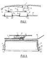
- Figure 1 is a schematic view showing installation of the installation according to the invention.
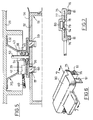
- Figure 2 is an exploded perspective view showing the installation of the installation.
- Figure 3 is a sectional view at a larger ladder showing the pavilion with its trim and installation.
- Figure 4 is an exploded perspective view of an alternative embodiment.
- Figure 5 shows in section the installation of the ceiling light on the pavilion.
- Figure 6 shows in perspective a variant a mounting plate.
- Figure 7 is a sectional view along the line 7-7 of figure 6.
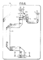
- Figure 8 is a schematic plan view showing a headliner arranged ready to be glued to a vehicle roof.
- Figure 9 is an enlarged sectional view scale along line 9-9 of figure 8.
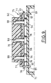
- Figure 10 is a sectional view along line 10-10 of Figure 4.
- Figure 11 is a sectional view along line 11-11 of figure 4.
- the internal face of a vehicle roof 1 is intended to receive an incoming beam 2 of current for powering different devices electric, ceiling, spot or other whose conductors 3 are stripped at a corresponding end and receive electrical connections 4 provided with crimping lugs 5 and 6, the lugs 5 being intended to enclose a conductor 3 and the legs 6 the stripped part, said organs being terminated by a washer 7 (see figure 2).
- the organs 4 are housed in a connector insulator 8 comprising a series of separate channels 9 by partitions 10, each channel having a hole 11 with each of which the washer coincides 7.
- the boxes are modular and can be assembled one at the ends of the other.
- the end of harness 2, opposite to that connected to the connector 8, has a socket 12 intended to be connected to a power supply.
- a ceiling lamp 15 On the housing of a ceiling lamp 15 are provided with pins 16 electrically connected to a lighting lamp, for example, with interposition a switch. The realization of the ceiling light is not shown here.
- the pins 16 comprise, at near their free end, a slot 22 for allow development such as riveting.
- each eyelet 20 being crimped on a track 19a if it is a printed circuit or on a conductor, if we use conductors in tablecloth.
- the other end of the printed circuit 19 has eyelets 20a.
- a housing 15a On a lining 23 are fixed, in a opening 24, the housing 15 and, in an opening 26, a housing 15a, the latter constituting, for example, the rear ceiling lamp of a vehicle, while the box 15 constitutes the front courtesy light.
- the box 15 has elastic tabs 21 allowing its installation and its retention, once engaged in the opening 24, this being bordered by a crimped ring 25.
- the housing 15a is mounted in the same way with elastic tabs 21a in the opening 26 of the lining 23 and has pins 16a intended to receive the corresponding eyelets 20a of the printed circuit 19.
- the lining 23 is thus delivered with the housings 15 and 15a, the printed circuit 19 mounted on pins 16 and 16a, an insulating cap 27 being mounted on pins 16a and pins 16 engaged in washers 7 and riveted at their free end.
- the filling thus is then glued to the roof, while the socket 12 is connected to a suitable power source.
- This embodiment is a simplified mode providing only two fixed electrical devices in pavilion 1.
- fixed connectors 30 comprising a body 31 of insulating material with two pierced tabs 32 of holes 33 for fixing by screws, rivets or others on said pavilion 29.
- Each connector 30 is of a modular type that is to say that it can be fixed, by one end, at the end of another.
- the assembly is carried out by tails dovetails provided at said ends.
- the connectors 30 receive organs of electrical contacts 36 having a part in shape of a truncated cone 38 whose small base ends by a flaring 37, this part 38 being integral of crimping lugs 39 for fixing a electrical conductor 40.
- Connectors 30 have tracks 42 opening onto housings 43 pierced with a hole 44 and in which extend locking members 45 of part 38. These organs 45 have a opening encasing the external surface of the part in the shape of a truncated cone to the right of the smallest diameter.
- each channel 42 is inserted an organ electrical contact 36, the part of which truncated cone 38, is located to the right of the hole corresponding 44.
- the part in the shape of a truncated cone 38 may include a radial slot 50.
- an elastic washer 93 comprising a series of legs 94 inclined towards the blocking member 45. These legs 94 form harpoons so that one element, engaged between them, can no longer be removed.
- the housing of a form 51 ceiling light general parallelepiped has a bottom 52 from from which a series of pins 53 is erected intended for receive eyelets 54 integral with the tracks 55 of a printed circuit 56.
- the printed circuit can be replaced by a sheet of conductors.
- Part of the pins 53 is intended to supply a housed lamp in the ceiling unit 51 with interposition a switch. This fitting of the ceiling light is not shown here.
- the housing 51 is housed in a housing 100 which has holes 101 for passage pins 53 and holes 102 intended to be crossed by pins 103 of branch pads 104 formed by a base 105 made of insulating material from from which two or three pins are erected 103.
- the housing 51 has elastic tabs 106 allowing its engagement and fixation in an opening 107 of the casing 100.
- the housing 100 is fixed in a hole 108 of a lining 70, the edge of the opening being reinforced by a crimped ring 109.
- the casing 100 laterally, is provided elastic legs 111 which allow its engagement in opening 108 and opposes its removal a once mounted.
- the eyelets 54 are held on the pins 53 by fixing plates 58 formed of a plastic body 62 with, on one side, elastic legs 59 provided with a hook 60, these being intended to pass through openings 61 of the printed circuit and lights 57 of the housing 100, the hooks 60, cooperating with the edges of the lights 57, ensuring the fixing.
- each hole 65 and the groove corresponding of a bar extend opposite an opening 67 of the wafer 58.
- each groove 66 It can be provided, in each groove 66, a slot 68 opening in the hole 65 in order to allow some distortion.
- FIG. 6 and 7 there is shown a mounting plate 75 which is intended to be used with certain devices, for example, with rear ceiling light of a vehicle, mirror or whatever.
- This plate 75 is made up by a molded plastic body, with fixing lugs 76 terminated by hooks 81, said tabs being intended to pass through the openings 61 and corresponding lights 92 of said devices.
- elastic metal bars 77 which have, each, a groove 78 circumscribing a hole 79, the grooves being located at the right of an opening 74 of the plate located on the side of the legs 76.
- the plate fixing On the side opposite to that provided with the legs, the plate fixing has a cap 80 for receiving pins 53 and isolate them electrically.
- the elastic metal bars 77 comprising a radial slot opening into hole 79.
- FIG 8 there is shown schematically in plan, headliner 70 ready to be placed with, on its face intended to be glued on the roof, flexible printed circuits 56, 56a and 56b.
- a device is provided lighting of a mirror 71 located opposite the front right seat of the vehicle, a transceiver electronic 72 for central locking control doors, a rear overhead light 73, the overhead light 51 which may include a reading spot 74.
- the pins 53 of the ceiling light 51 pass through the holes 101 of the housing 100, the eyelets 54 being mounted on the pins 53 and the pads 58 being engaged on said pins.
- the rear dome 73 has pins 88 which receive the eyelets 54 of the printed circuit corresponding, the pins receiving a plate fixing 75 which ensures, on the one hand, the fixing from the corresponding end of the printed circuit, the insulation electric pins 88, legs 76 fitting into the openings 92 thereof which correspond to the openings 57 (see FIGS. 8 and 9).
- Holes 79 like holes 65, have a slightly smaller diameter than the pins 53 and 88 so that they sink into force and that thus, once engaged in said holes, they cannot be extracted unexpectedly, the gorges 78 and 66 facilitating the engagement of the pins.
- the holes 79 may also have radial slots.
- the transceiver 72 is connected by a printed circuit 56b to pins 103 of a pad 104 and said transmitter has pins 89 receiving a mounting plate 75.
- the mounting is therefore the same as that of the rear dome 73.
- the mirror lamp 71 is powered by a printed circuit 56a interposed between pins 103 of a second pad 104 and pins 90 of said device, the latter being fixed to the lining 70 by a plate 75 which also ensures the fixing printed circuit eyelets.
- This assembly corresponds to those of the rear dome 73 and the transceiver 72.
- a connector 30 or a series of connectors 30 assembled end to end, these receiving, in the channels 42, organs 36 connected by conductors 40 to the power supply, the contacts 36 being wedged in the housings 43 by the organs 45.
- the packing 70 provided with printed circuits 56, 56a and 56b of the ceiling lights, etc ..., is presented opposite of the corresponding surface of pavilion 29 duly glued so that the pins 53 pass through the washers 93, the tabs 94 of which secure final and fit into the shaped parts truncated cone 38 whose opening described by the small base is slightly smaller than the diameter pins 53 so that they sink into force in order to achieve an efficient electrical connection.
- Pins 102 are similarly engaged in the washers 93 and in the trunk-shaped parts of cone 38.
- the trim is fixed on the roof simultaneously. So, without any tool, we realize, when installing the trim, on the one hand, the connections electrical and, on the other hand, the mounting of circuits and electrical devices on the pavilion.
Landscapes
- Engineering & Computer Science (AREA)
- Mechanical Engineering (AREA)
- Arrangements Of Lighting Devices For Vehicle Interiors, Mounting And Supporting Thereof, Circuits Therefore (AREA)
- Vehicle Interior And Exterior Ornaments, Soundproofing, And Insulation (AREA)
- Coupling Device And Connection With Printed Circuit (AREA)
Claims (12)
- Einrichtung zur Stromversorgung elektrischer Einrichtungen an Fahrzeugdächern, wie Deckenleuchte (15,51), Steuervorrichtung (72) zur Zentralverriegelung von Türen u.dgl., mit zumindest einem elektrischen Verbinder (8,30), der mit elektrischen Kontaktorganen (4,36) versehen ist, die dazu vorgesehen sind, über Leiter (3,40) mit einer elektrischen Stromquelle verbunden zu werden, und wobei das Dach dazu vorgesehen ist, eine Verkleidung (23,70) aufzunehmen, an der die verschiedenen elektrischen Einrichtungen (15,51) angebracht sind, wobei genannte Einrichtung dadurch gekennzeichnet ist, daß die Verkleidung (23,70) die verschiedenen elektrischen Einrichtungen vormontiert und vorverkabelt enthält, welche aus zumindest zwei Einrichtungen gebildet sind, die jede eine Reihe von Kontaktstiften (16,53,88) aufweist, die elektrische Verbindungsorgane bilden, daß die Kontaktstifte der zwei Einrichtungen Kontaktösen (20,54) von Leiterbündeln (19,56), wie gedruckte Schaltungen, aufnehmen, die die Vorverkabelung bilden, und daß die Kontaktstifte der einen der genannten Einrichtungen (51) dazu vorgesehen sind, an elektrischen Kontaktorganen (4,36) des elektrischen Verbinders (8,30) befestigt zu werden und Mittel (75) vorgesehen sind, um die Kontaktstifte (88) der anderen Einrichtung elektrisch zu isolieren.
- Einrichtung zur Stromversorgung elektrischer Einrichtungen nach Anspruch 1, dadurch gekennzeichnet, daß die elektrischen Kontaktorgane der Verbinder durch Ringscheiben (4) gebildet sind, die radiale Klemmlaschen für elektrische Leiter besitzen, daß die Kontaktstifte (16) an ihrem freien Ende Schlitze (22) aufweisen, damit man nach dem Eintreten in die Ringscheiben (7) eine Vernietung bewirken kann.
- Einrichtung zur Stromversorgung elektrischer Einrichtungen nach Anspruch 1, dadurch gekennzeichnet, daß sie einen Kasten (100) aufweist, der mit Mitteln (111) für seine Befestigung in einer Öffnung (108) der Verkleidung (70) versehen und zur Aufnahme eines Gehäuses (51) einer elektrischen Einrichtung vorgesehen ist, daß genannter Kasten einen Boden besitzt, der durch eine erste Reihe von Löchern (101) durchzogen ist, die dazu vorgesehen sind, durch die Kontaktstifte (53) des Gehäuses durchgriffen zu werden, und eine zweite Reihe von Löchern (102) aufweist, die dazu vorgesehen sind, durch die Kontaktstifte (103) von Abzweigkontakten (104) durchgriffen zu werden.
- Einrichtung zur Stromversorgung elektrischer Einrichtungen nach Anspruch 1, dadurch gekennzeichnet, daß sie Befestigungsplatten (58) aufweist, die dazu vorgesehen sind, auf den Kontaktstiften angebracht zu werden, um die Ösen mit den genannten Kontaktstiften in Eingriff zu halten.
- Einrichtung zur Stromversorgung elektrischer Einrichtungen nach den Ansprüchen 1 und 4, dadurch gekennzeichnet, daß die Befestigungsplatten (58) Mittel (59,60) für ihre Befestigung am Kasten (100) aufweisen.
- Einrichtung zur Stromversorgung elektrischer Einrichtungen nach Anspruch 1, dadurch gekennzeichnet, daß die Mittel zur elektrischen Isolierung der Kontaktstifte (88) der anderen Einrichtung eine Befestigungsplatte (75) aufweisen, die zur Anordnung auf den Kontaktstiften (88) zum Sicherstellen des Haltens der Ösen (54) auf den genannten Kontaktstiften vorgesehen und durch eine Haube (80) abgeschlossen ist, die die genannten Kontaktstifte überdeckt.
- Einrichtung zur Stromversorgung elektrischer Einrichtungen nach Anspruch 4, dadurch gekennzeichnet, daß die Befestigungsplatten (58) aus einem isolierenden Kunststoffmaterial hergestellt sind, in dem federnde metallische Schienen (64) teilweise eingebettet sind, die von einem Loch (65) für den Durchgriff der Kontaktstifte (53, 103) durchzogen sind, daß die genannten Löcher (65) durch eine Rille (66) umgrenzt sind, wobei der Durchmesser der Löcher (65) etwas kleiner als der Querschnitt der Kontaktstifte ist, und daß zumindest ein radialer Schlitz in den genannten federnden Schienen ausgebildet ist und in die Löcher (65) mündet.
- Einrichtung zur Stromversorgung elektrischer Einrichtungen nach Anspruch 6, dadurch gekennzeichnet, daß die für die Ösen (54) auf den Kontaktstiften (88) der anderen Einrichtung vorgesehenen Befestigungsplatten (75), die eine die Kontaktstifte überdeckende Haube (80) aufweisen, aus einem isolierenden Kunststoffmaterial hergestellt sind, daß federnde metallische Schienen (77) teilweise in das Kunststoffmaterial eingebettet sind und ein Loch (79) für den Durchtritt der Kontaktstifte aufweisen, welches durch eine Rille (74) umgrenzt ist, wobei der Durchmesser des Loches (79) etwas kleiner ist als der Querschnitt der Kontaktstifte (88), und daß zumindest ein Schlitz radial ausgebildet ist und in das Loch (79) mündet.
- Einrichtung zur Stromversorgung elektrischer Einrichtungen nach Anspruch 1, dadurch gekennzeichnet, daß die elektrischen Kontaktorgane (4) des elektrischen Verbinders (8) Ringscheiben aufweisen, die dazu vorgesehen sind, durch die Kontaktstifte durchgriffen zu werden, die an ihrem freien Ende so ausgebildet sind, daß sie an den genannten Ringscheiben festgeklemmt werden.
- Einrichtung zur Stromversorgung elektrischer Einrichtungen nach Anspruch 1, dadurch gekennzeichnet, daß der Verbinder (30) Mittel (93,94) zum Blockieren der Kontaktstifte (53,103) aufweist.
- Einrichtung zur Stromversorgung elektrischer Einrichtungen nach Anspruch 10, dadurch gekennzeichnet, daß der Verbinder (30) eine Reihe von teilweise eingebetteten, federnden Ringscheiben (93) aufweist, die jede eine Reihe von Laschen (94) besitzen, die einen Durchgang für einen Kontaktstift (53,103) begrenzen, wobei die Laschen so geneigt sind, daß sie sich federnd beim Einsetzen der Kontaktstifte spreizen und Anker bilden, die dem Herausziehen der genannten Kontaktstifte entgegenwirken.
- Einrichtung zur Stromversorgung elektrischer Einrichtungen nach den Ansprüchen 10 und 11, dadurch gekennzeichnet, daß die elektrischen Kontaktorgane einen Teil in Form eines Kegelstumpfes (38) aufweisen, dessen große Basis der Seite der Blockiermittel für die Kontaktstifte zugewandt ist und dessen kleine, offene Basis einen Durchmesser bildet, der etwas geringer ist als der Durchmesser der Kontaktstifte (53,103), wobei die genannte kleine Basis einen radialen Schlitz (50) aufweist.
Applications Claiming Priority (2)
| Application Number | Priority Date | Filing Date | Title |
|---|---|---|---|
| FR9608863A FR2751481B1 (fr) | 1996-07-16 | 1996-07-16 | Installation d'alimentation de dispositifs electriques sur des pavillons de vehicules |
| FR9608863 | 1996-07-16 |
Publications (2)
| Publication Number | Publication Date |
|---|---|
| EP0820119A1 EP0820119A1 (de) | 1998-01-21 |
| EP0820119B1 true EP0820119B1 (de) | 1999-11-03 |
Family
ID=9494087
Family Applications (1)
| Application Number | Title | Priority Date | Filing Date |
|---|---|---|---|
| EP97401665A Expired - Lifetime EP0820119B1 (de) | 1996-07-16 | 1997-07-10 | Installation der Stromversorgung elektrischer Verbraucher an Fahrzeugdächern |
Country Status (4)
| Country | Link |
|---|---|
| EP (1) | EP0820119B1 (de) |
| DE (1) | DE69700731T2 (de) |
| ES (1) | ES2139425T3 (de) |
| FR (1) | FR2751481B1 (de) |
Families Citing this family (5)
| Publication number | Priority date | Publication date | Assignee | Title |
|---|---|---|---|---|
| DE19734032C1 (de) * | 1997-08-06 | 1998-12-17 | Siemens Ag | Elektronisches Steuergerät mit Kontaktstift sowie Herstellungsverfahren |
| DE19825692A1 (de) * | 1998-06-09 | 1999-12-16 | Alcatel Sa | Drehverbinder mit Flachbandleitung und Rundleiter |
| FR2788888B1 (fr) * | 1999-01-26 | 2001-04-13 | Sylea | Connecteur electrique pour cable plat |
| DE102005027852A1 (de) | 2005-06-16 | 2006-12-21 | Robert Bosch Gmbh | Anordnung und Verfahren zum elektrischen Anschluss einer elektronischen Schaltung in einem Gehäuse |
| JP5674147B2 (ja) * | 2011-04-28 | 2015-02-25 | 矢崎総業株式会社 | 車輌用室内照明灯の取り付け構造 |
Family Cites Families (4)
| Publication number | Priority date | Publication date | Assignee | Title |
|---|---|---|---|---|
| GB1597913A (en) * | 1978-02-24 | 1981-09-16 | Ford Motor Co | Circuit board assembly |
| JPS56126280A (en) * | 1980-03-10 | 1981-10-03 | Nissan Motor | Connector for flexible printed board |
| US4640561A (en) * | 1985-11-15 | 1987-02-03 | Ford Motor Company | Flexible printed circuit connector |
| DE4139434C2 (de) * | 1990-11-30 | 1997-01-30 | Yazaki Corp | Aufbau einer elektrischen Verkabelung für elektrische Komponenten in einem Fahrzeugarmaturenbrett und zum Anschluß an das Bordnetz eines Kraftfahrzeugs |
-
1996
- 1996-07-16 FR FR9608863A patent/FR2751481B1/fr not_active Expired - Fee Related
-
1997
- 1997-07-10 ES ES97401665T patent/ES2139425T3/es not_active Expired - Lifetime
- 1997-07-10 DE DE69700731T patent/DE69700731T2/de not_active Expired - Fee Related
- 1997-07-10 EP EP97401665A patent/EP0820119B1/de not_active Expired - Lifetime
Also Published As
| Publication number | Publication date |
|---|---|
| FR2751481A1 (fr) | 1998-01-23 |
| DE69700731D1 (de) | 1999-12-09 |
| DE69700731T2 (de) | 2000-07-20 |
| EP0820119A1 (de) | 1998-01-21 |
| ES2139425T3 (es) | 2000-02-01 |
| FR2751481B1 (fr) | 1998-09-04 |
Similar Documents
| Publication | Publication Date | Title |
|---|---|---|
| FR2788888A1 (fr) | Connecteur electrique pour cable plat | |
| EP1151499B1 (de) | Elektrische schalteranordnung | |
| FR2793955A1 (fr) | Dispositif pour relier electriquement une ligne coaxiale a une carte de circuit imprime | |
| FR2729509A1 (fr) | Connecteur electrique | |
| FR2684242A1 (fr) | Assemblage de connecteur electrique comportant un element de verrouillage des bornes. | |
| EP0820119B1 (de) | Installation der Stromversorgung elektrischer Verbraucher an Fahrzeugdächern | |
| FR2867838A1 (fr) | Lampe d'eclairage interieur | |
| EP0624495A1 (de) | Elektrische Baugruppe für die Multiplexsteuerung einer Beleuchtungs- oder Signaleinrichtung an Kraftfahrzeugen | |
| EP0289429A1 (de) | Rahmenelementengruppe, um Kabelbündel zu realisieren | |
| FR2699744A1 (fr) | Groupe boîte à bornes-câbles, en particulier pour l'alimentation électrique d'appareils électroménagers. | |
| EP0660461B1 (de) | Mehrfacher Sockel für Steckdose | |
| EP1100105A1 (de) | Verdrahtungsvorrichtung für Schutzschaltung | |
| EP0547929B1 (de) | Elektrische Anschlussbuchse, insbesondere für Kraftfahrzeuge | |
| EP0860901B1 (de) | Gehäuse für elektrischen Gerät und elektrische Vorrichtung mit einem solchen Gehäuse | |
| FR2802718A1 (fr) | Boite a fusibles pour vehicules automobiles | |
| FR2759529A1 (fr) | Appareil electrique comportant un agencement de connexion solidaire de sa plaque de circuit imprime | |
| EP0416965A1 (de) | Vorrichtung zum Anschliessen eines Abzweigleiters an einen isolierten Hauptleiter | |
| EP0669696B1 (de) | Modulare Speise- und Steuereinheit für einen Wechselstromgenerator eines Fahrzeugs | |
| EP1248330B1 (de) | Elektrische Leistungssteckdose für KFZ mit eingebauter Beleuchtungsvorrichtung | |
| EP0720250B1 (de) | Kraftfahrzeugantenne und Anpassungsvorrichtung mit aktiver Impedanz für eine solche Antenne | |
| FR2748977A1 (fr) | Motoreducteur pour essuie-glace et organe de connexion associe | |
| FR2806249A1 (fr) | Montage des circuits decoupes sur des supports de lampes | |
| FR2823914A1 (fr) | Dispositif de blindage electromagnetique pour connecteur electrique | |
| FR2732824A1 (fr) | Prise bi-tension | |
| EP0739070B1 (de) | Elektrische Verbindungsvorrichtung für die Kupplung eines Elektrogerätes am Netz |
Legal Events
| Date | Code | Title | Description |
|---|---|---|---|
| PUAI | Public reference made under article 153(3) epc to a published international application that has entered the european phase |
Free format text: ORIGINAL CODE: 0009012 |
|
| AK | Designated contracting states |
Kind code of ref document: A1 Designated state(s): DE ES GB IT |
|
| 17P | Request for examination filed |
Effective date: 19980519 |
|
| AKX | Designation fees paid |
Free format text: DE ES GB IT |
|
| RBV | Designated contracting states (corrected) |
Designated state(s): DE ES GB IT |
|
| GRAG | Despatch of communication of intention to grant |
Free format text: ORIGINAL CODE: EPIDOS AGRA |
|
| GRAG | Despatch of communication of intention to grant |
Free format text: ORIGINAL CODE: EPIDOS AGRA |
|
| GRAH | Despatch of communication of intention to grant a patent |
Free format text: ORIGINAL CODE: EPIDOS IGRA |
|
| 17Q | First examination report despatched |
Effective date: 19990324 |
|
| GRAH | Despatch of communication of intention to grant a patent |
Free format text: ORIGINAL CODE: EPIDOS IGRA |
|
| GRAA | (expected) grant |
Free format text: ORIGINAL CODE: 0009210 |
|
| AK | Designated contracting states |
Kind code of ref document: B1 Designated state(s): DE ES GB IT |
|
| ITF | It: translation for a ep patent filed | ||
| REF | Corresponds to: |
Ref document number: 69700731 Country of ref document: DE Date of ref document: 19991209 |
|
| GBT | Gb: translation of ep patent filed (gb section 77(6)(a)/1977) |
Effective date: 19991207 |
|
| REG | Reference to a national code |
Ref country code: ES Ref legal event code: FG2A Ref document number: 2139425 Country of ref document: ES Kind code of ref document: T3 |
|
| PLBE | No opposition filed within time limit |
Free format text: ORIGINAL CODE: 0009261 |
|
| STAA | Information on the status of an ep patent application or granted ep patent |
Free format text: STATUS: NO OPPOSITION FILED WITHIN TIME LIMIT |
|
| 26N | No opposition filed | ||
| REG | Reference to a national code |
Ref country code: GB Ref legal event code: IF02 |
|
| PGFP | Annual fee paid to national office [announced via postgrant information from national office to epo] |
Ref country code: GB Payment date: 20030704 Year of fee payment: 7 |
|
| PGFP | Annual fee paid to national office [announced via postgrant information from national office to epo] |
Ref country code: DE Payment date: 20030708 Year of fee payment: 7 |
|
| PGFP | Annual fee paid to national office [announced via postgrant information from national office to epo] |
Ref country code: ES Payment date: 20030714 Year of fee payment: 7 |
|
| PG25 | Lapsed in a contracting state [announced via postgrant information from national office to epo] |
Ref country code: GB Free format text: LAPSE BECAUSE OF NON-PAYMENT OF DUE FEES Effective date: 20040710 |
|
| PG25 | Lapsed in a contracting state [announced via postgrant information from national office to epo] |
Ref country code: ES Free format text: LAPSE BECAUSE OF NON-PAYMENT OF DUE FEES Effective date: 20040712 |
|
| PG25 | Lapsed in a contracting state [announced via postgrant information from national office to epo] |
Ref country code: DE Free format text: LAPSE BECAUSE OF NON-PAYMENT OF DUE FEES Effective date: 20050201 |
|
| GBPC | Gb: european patent ceased through non-payment of renewal fee |
Effective date: 20040710 |
|
| PG25 | Lapsed in a contracting state [announced via postgrant information from national office to epo] |
Ref country code: IT Free format text: LAPSE BECAUSE OF NON-PAYMENT OF DUE FEES Effective date: 20050710 |
|
| REG | Reference to a national code |
Ref country code: ES Ref legal event code: FD2A Effective date: 20040712 |