EP0820400B3 - Mooring bed assessment apparatus and method - Google Patents
Mooring bed assessment apparatus and method Download PDFInfo
- Publication number
- EP0820400B3 EP0820400B3 EP96912098A EP96912098A EP0820400B3 EP 0820400 B3 EP0820400 B3 EP 0820400B3 EP 96912098 A EP96912098 A EP 96912098A EP 96912098 A EP96912098 A EP 96912098A EP 0820400 B3 EP0820400 B3 EP 0820400B3
- Authority
- EP
- European Patent Office
- Prior art keywords
- trajectory
- soil
- body member
- burying
- data
- Prior art date
- Legal status (The legal status is an assumption and is not a legal conclusion. Google has not performed a legal analysis and makes no representation as to the accuracy of the status listed.)
- Expired - Lifetime
Links
- 238000000034 method Methods 0.000 title claims description 10
- 239000002689 soil Substances 0.000 claims abstract description 85
- 238000005259 measurement Methods 0.000 claims abstract description 30
- 238000009933 burial Methods 0.000 claims abstract description 25
- 230000035515 penetration Effects 0.000 claims abstract description 12
- 241000935974 Paralichthys dentatus Species 0.000 claims description 21
- 238000006073 displacement reaction Methods 0.000 claims description 8
- 238000000926 separation method Methods 0.000 claims description 8
- 238000003860 storage Methods 0.000 claims description 6
- 230000001133 acceleration Effects 0.000 claims description 5
- 230000005540 biological transmission Effects 0.000 claims description 5
- 230000010354 integration Effects 0.000 claims description 3
- 238000004519 manufacturing process Methods 0.000 claims description 2
- 239000000463 material Substances 0.000 claims description 2
- 239000000126 substance Substances 0.000 claims description 2
- 230000001419 dependent effect Effects 0.000 claims 1
- 239000004020 conductor Substances 0.000 description 6
- 239000004927 clay Substances 0.000 description 5
- 230000005355 Hall effect Effects 0.000 description 4
- 238000012360 testing method Methods 0.000 description 4
- XLYOFNOQVPJJNP-UHFFFAOYSA-N water Substances O XLYOFNOQVPJJNP-UHFFFAOYSA-N 0.000 description 4
- 230000007423 decrease Effects 0.000 description 3
- 238000005520 cutting process Methods 0.000 description 2
- 239000004519 grease Substances 0.000 description 2
- 238000000691 measurement method Methods 0.000 description 2
- 239000000523 sample Substances 0.000 description 2
- 238000005070 sampling Methods 0.000 description 2
- 238000004873 anchoring Methods 0.000 description 1
- 238000012512 characterization method Methods 0.000 description 1
- 238000005553 drilling Methods 0.000 description 1
- 238000011835 investigation Methods 0.000 description 1
- 238000009533 lab test Methods 0.000 description 1
- 239000002184 metal Substances 0.000 description 1
- 238000012986 modification Methods 0.000 description 1
- 230000004048 modification Effects 0.000 description 1
- 239000011148 porous material Substances 0.000 description 1
- 230000003068 static effect Effects 0.000 description 1
Images


Classifications
-
- B—PERFORMING OPERATIONS; TRANSPORTING
- B63—SHIPS OR OTHER WATERBORNE VESSELS; RELATED EQUIPMENT
- B63B—SHIPS OR OTHER WATERBORNE VESSELS; EQUIPMENT FOR SHIPPING
- B63B21/00—Tying-up; Shifting, towing, or pushing equipment; Anchoring
-
- B—PERFORMING OPERATIONS; TRANSPORTING
- B63—SHIPS OR OTHER WATERBORNE VESSELS; RELATED EQUIPMENT
- B63B—SHIPS OR OTHER WATERBORNE VESSELS; EQUIPMENT FOR SHIPPING
- B63B21/00—Tying-up; Shifting, towing, or pushing equipment; Anchoring
- B63B21/22—Handling or lashing of anchors
-
- G—PHYSICS
- G01—MEASURING; TESTING
- G01V—GEOPHYSICS; GRAVITATIONAL MEASUREMENTS; DETECTING MASSES OR OBJECTS; TAGS
- G01V1/00—Seismology; Seismic or acoustic prospecting or detecting
- G01V1/38—Seismology; Seismic or acoustic prospecting or detecting specially adapted for water-covered areas
-
- B—PERFORMING OPERATIONS; TRANSPORTING
- B63—SHIPS OR OTHER WATERBORNE VESSELS; RELATED EQUIPMENT
- B63B—SHIPS OR OTHER WATERBORNE VESSELS; EQUIPMENT FOR SHIPPING
- B63B21/00—Tying-up; Shifting, towing, or pushing equipment; Anchoring
- B63B21/24—Anchors
- B63B21/26—Anchors securing to bed
- B63B2021/262—Anchors securing to bed by drag embedment
Definitions
- the present invention relates to a mooring bed assessment apparatus and method.
- the drag embedment anchors are being assessed as anchoring elements in a spread mooring for deployment in a submerged marine mooring bed, it is desirable to have knowledge of the engineering properties of the mooring bed soil at co-ordinate points on the trajectory that each anchor is expected to follow as it buries in the mooring bed in response to a large pulling force applied substantially horizontally to its attached pulling cable.
- drag embedment anchors of the most modern designs have been shown experimentally to follow a trajectory which penetrates as much as five fluke lengths below the surface of a frequently-occurring normally consolidated clay seabed, of shear strength gradient 1.6kPa/m, when pulled by a chain cable.
- the trajectory penetrates as much as nine fluke lengths.
- the burial trajectory forms a curve that decreases progressively in inclination to the horizontal from 50° at the initial penetration point until it becomes horizontal at a maximum anchor holding capacity of about 40 times anchor weight when the anchor has moved about 300 metres horizontally and buried about 54 metres vertically.
- engineering data for the mooring bed soil over a planar vertical area extending at least 300 metres along the sea bed surface and 54 metres below it at each of as many as twelve widely-separated locations in a spread mooring site to enable each trajectory to be predicted.
- Horizontal co-ordinates on a trajectory have been determined by obtaining approximate horizontal displacements of the anchor by measuring the corresponding horizontal displacements of a designated point on a horizontal portion of its pulling cable which has not buried under the seabed surface.
- Corresponding vertical co-ordinates have been determined either directly, by using a thin cable attached to the anchor and pulled up vertically to measure its depth of penetration below the seabed surface, or indirectly, by using a pressure sensor mounted on the anchor to measure the static pressure of the column of water from the buried anchor to the sea surface via a flexible tube serving to conduct the water column from the seabed surface to the anchor.
- disadvantages of these past measurement methods include lack of certainty that the thin cable has been pulled up taut enough to become truly vertical in the soll without disturbing the buried anchor and the necessity for numerous repetitions of this operation.
- disadvantages of these past measurement methods include uncertainty due to pressure fluctuations caused by long swells at the surface of the sea and occlusion of the water column conducting tube by wall collapse due to soil pressure, by kinking, or by ingress of soil at its free end.
- An object of the present invention is to provide apparatus for producing measurement data capable of characterising a burial trajectory traced out by a point on a burying apparatus burying in a mooring bed soil.
- a subsidiary object of the present invention is to provide a drag embedment burying apparatus capable of establishing a deep burial trajectory in a sea bed soil while producing a horizontal resistance to draw embedment substantially less than would be produced by a drag embedment anchor and its cable while establishing such a trajectory in the soil.
- Another subsidiary object of the present invention is to provide apparatus for measuring an engineering characteristic of said soil at characterising points on said trajectory traced out by said point on said burying apparatus.
- Another object of the present invention is to provide a method for assessing the anchorability of a marine mooring bed by interpreting the shape of a burial trajectory produced therein by said drag embedment burial apparatus.
- an apparatus for producing measurement data capable of characterising a burial trajectory in a sea-bed soil
- said apparatus comprising assessment means including a body member for inclusion in a burying apparatus adapted for burying in a sea-bed soil, said assessment means being adapted to produce data for determining positions in the soil of a point (P) on said burying apparatus or body member during burial to enable determination of the trajectory of said point (P), said assessment means including measurement means responsive to movement of the burying apparatus and wherein the measurement means is adapted to produce an electrical pulse output defining successive points of known fixed separation on the trajectory, and wherein the electrical pulse output triggers the measurement means to produce said data at said points on the trajectory.
- an apparatus for establishing and characterising a burial trajectory in a sea-bed soil comprises the inventive characteristic-measuring apparatus as defined above included in a burying apparatus which includes a wire rope pulling cable attached to one end of an elongate shank member another end of which is attached to a fluke member for drag embedment in said soil along a trajectory lying in a vertical fore-and-aft central plane (x-x) of the burying apparatus, wherein the minimum projected area of said shank member and said fluke member projected in a particular direction in said plane does not exceed 20 per cent (and preferably does not exceed 10 per cent) of the corresponding maximum projected area projected at right-angles to said direction in said plane.
- said measurement means serves to measure distance along the trajectory separating two spaced points thereon and additionally a further parameter comprising any of
- said means for measuring distance along said trajectory separating two points thereon is included in said body member.
- said body member is elongated and hollow and pivotably connected to said point on said burying apparatus whereby it can axially align itself in said trajectory.
- a line member attached to said body member is provided which is streamable out behind said body member to coincide with said trajectory as the burying apparatus buries into the mooring bed soil.
- said body member has an internal compartment containing storage means which stores said line member.
- said line member at an end remote from its attachment to said body member is attached to a resistive element external to said body member which resists penetration into and remains on the mooring bed surface as said body member moves along said trajectory whereby the line member is drawn out of the body member to coincide with said trajectory.
- said means for measuring distance between points along said trajectory is actuated by said line member as it exits from said body member.
- said means for measuring distance between points along said trajectory comprises a pulley wheel mounted in said body member and turnable by passage thereover of said line member as it is drawn out of said body member and a magnet orbitally rotated by said pulley wheel to trigger a magnetic field sensing switch in said body member to provide an electrical pulse output which defines successive points of known fixed separation on said line member occupying said trajectory as said pulley wheel is turned by the exiting line member.
- said measuring means for providing data from which the angle of inclination of the trajectory at a point on the trajectory may be determined comprises an electrical inclinometer device rigidly attached to said body member the output of which is sampled using the point-defining pulse from said magnetic field sensing circuit in said body member.
- the inclinometer device comprises an accelerometer arranged to provide an output voltage proportional to the product of the earth's gravitational acceleration and the cosine of the angle of tilt of the accelerometer relative to the horizontal,
- the body member contains an electrically driven data logger to store the inclination angle measurement data of all of the pulse-defined points of known fixed separation along said line member occupying said trajectory.
- said storage means for said line member comprises a helically wound coil with the line member drawable out from the inside of the coil,
- said internal compartment containing said storage means is filled with a grease-like substance.
- said compartment is closed by a sealed sliding piston pierced by an orifice close fitting about the line member which exits therethrough whereby pressure-induced movement of the piston as the line member exits eliminates pressure differentials across the piston and so prevents ingress of mooring bed soil material into said compartment.
- the line member comprises an electrical cable which serves additionally to conduct data by way of electrical signals from the body member along the path of the trajectory to an acoustic transponder adjacent the mooring bed surface whereby the trajectory characterising data may be transmitted to a receiver adjacent the surface of the sea.
- said means for measuring distance between points along said trajectory comprises turbine vanes mounted on a shaft protruding from said body member and a magnet attached to and orbitally rotated by said shaft to trigger a magnetic field sensing switch in said body member to provide an electrical pulse output which defines successive points of known fixed separation on said trajectory as said shaft is rotated by soil impingement on said vanes due to movement of said body member through the soil along said trajectory.
- said apparatus includes means for measuring a soil parameter such as for example penetration resistance.
- a soil parameter such as for example penetration resistance.
- said means for measuring soils parameter comprises an electrically readable penetrometer arranged to measure penetration resistance of said soil.
- an apparatus for producing measurement data capable of characterising a burial trajectory in a sea-bed soil
- said apparatus comprising assessment means including a body member for inclusion in a burying apparatus adapted for burying in a sea-bed soil, said assessment means being adapted to produce data for determining positions in the soil of a point (P) on said burying apparatus or body member during burial to enable determination of the trajectory of said point (P), said assessment means including measurement means responsive to movement of the burying apparatus to produce said data said measurement means including an accelerometer serving to measure acceleration whereby data is produced to enable determination of the position of said point (P) moving on the trajectory by utilising an integration process.
- a method for producing data for assessing the anchorability of a sea-bed soil in a marine mooring bed comprising:
- an apparatus 1 for establishing and characterising a burial trajectory 2 in a sea-bed soil 3 comprises a trajectory characteristic measuring apparatus 4 connected to a point P on a burying apparatus 5 formed by a relatively thin wire rope cable 6 pivotably attached to one end of a shank 7, the other end of which shank is attached to a fluke 8 for drag embedment burial through seabed surface 9 into seabed soil 3 when pulled horizontally thereon by a marine vessel 10 at the sea surface 11.
- Trajectory 2 lies in a vertical plane containing shank 7 and the central plane (x-x) of the burying apparatus ( Figs 3 and 4 ) and commences at the seabed surface 9 at an angle of inclination of approximately 50° to the horizontal. Trajectory 2 then progressively decreases in slope until it is horizontal at a depth of embedment D below the seabed surface 9.
- depth D may be in the range 9L to 18L and the trajectory 2 will become horizontal after apparatus 5 has been dragged a distance of approximately 40L to 50L measured horizontally.
- burying apparatus 5 is constructed with minimum projected area present for each of its components when viewed In a forward direction F ( Fig 2 ).
- Fluke 8 of length L, has maximum projected area A ( Fig 3 ) when viewed at right angles to direction F in the fore-and-aft central plane X-X containing shank 7.
- the diameter of wire rope 6 does not exceed A and preferably 24L does not exceed A.
- Shank 7 and fluke 8 are streamlined and have sharp forward cutting edges to minimise resistance to forward cutting edges to minimise resistance to forward movement in soil 3.
- the minimum projected area in direction F of shank 7 and fluke 8 combined does not exceed 0.2A and preferably does not exceed 0.12A.
- the minimum projected area in direction F of shank 7 does not exceed 0.1A.
- Cross-sections of fluke 8 in plans parallel to plan X-X are substantially wedge-shaped with a forward included angle of not more than 10° and preferably not more than 6°.
- the maximum depth of cross-sections adjacent plane X-X does not exceed o.15L and preferably does not exceed 0.07L.
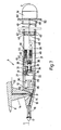
- a trajectory measuring apparatus 4 includes a hollow closed cylindrical metal body 12 having a forward conical nose portion 13 attached to a lug 14 protruding from a forward portion of the undersurface of fluke 8 of burying apparatus 5 by means of pivot 15 at point P which allows body 12 to align automatically with trajectory 2 due to impingement of undisturbed soil thereon.
- a tubular probe 16 is attached to conical nose portion 13 which carries a known industry standard cone - penetrometer 17 in undisturbed soil in advance of body 12, the cone of the penetrometer being axially symmetrical.
- the penetrometer 17 provides an electrical output proportional to soil pressure thereon.
- a soil flow turbine rotor 18, with four radial equally spaced vanes 19, is mounted on a shaft 20 protruding axially from a conical rear tail portion 21 of body 12. Shaft 20 also extends forwardly into an interior cavity 22 inside body 12.
- the area swept by the turbine vanes 19 exceeds the maximum cross-sectional area of body 12 sufficiently to ensure that passing soil 3 impinges on the vanes 19 to turn rotor 18 and shaft 20 as point P moves along trajectory 2 ( Fig 2 ) due to the pulling force in wire rope 6.
- Shaft 20 is fitted with a shaft seal 23 and bearing bushes 24 pressed into tail portion 21 of body 12.
- a disc 25 is mounted on shaft 20 in cavity 22 and carries a magnet 26.
- a Hall Effect magnetic switch 27 is mounted Inside cavity 22 adjacent disc 25 such that transit of magnet 26 past switch 27 as shaft 20 rotates produces an electrical pulse once for each revolution of turbine rotor 18. This electrical pulse thus denotes successively arriving equally spaced points on trajectory 2 with the spacing determined by the pitch chosen for the turbine vanes 19.
- a known voltage output accelerometer acting as a sensitive inclinometer 28, a datalogger 29, and a battery power supply 30 are mounted in cavity 22 of body 12.
- Inclinometer 28 is mounted with its vertical axis lying in the fore-and-aft plane of burial apparatus 5 which contains shank 7 and with its horizontal axis parallel to the axis body 12.
- the inclinometer (accelerometer) 28 gives a voltage output proportional to the product of the earth's gravitational acceleration g and the cosine of the angle ⁇ ( Fig 1 ) of inclination of its horizontal axis and the axis of body 12 to the horizontal. Since g is a constant, the output of inclinometer 28 is proportional to cos ⁇ .
- the output of inclinometer 28 and cone - penetrometer 17 are sampled by datalogger 29 and stored therein on the arrival of each asynchronous position-denoting pulse from switch 27.
- Wire rope 6 is constructed to include electrical conductor wires 53 ( Fig 2 ) to permit equipment in vessel 10 to receive and store the sampled outputs as they are stored in datalogger 29. This allows the sampled outputs to be monitored as trajectory 2 is being established, with the datalogger 29 acting as a safeguard against loss of data due to possible disruption of the signal path between body 12 and the equipment on marine vessel 10.
- An electrical jumper cable 52 is fitted to buying apparatus 5 leading from an electrical connector 54 on conductor wires 53 in wire rope 6 via shank 7, fluke 8, and lug 14, to connect with the datalogger 29 in body 12.
- an alternative cylindrical tail portion 31 is fitted to body 12 instead of tail portion 12 of Fig 5 and the device of Fig 7 has a somewhat different operation from the device of Fig 5 as will be explained later.
- a shaft 32 is mounted in a forward wall 33 of tail portion 31 by means of bearing bush 34 and shaft seal 35 and protrudes into cavity 22.
- Disc 36 is mounted on one end of shaft 32 within cavity 22 and carries a magnet 37 to actuate Hall Effect switch 27 as previously described.
- a bevel gear 38 is mounted on the other end of shaft 32 in a grease filled cavity 39 inside tail portion 31.
- a bevel gear 40 meshes with bevel gear 38 and is fixed coaxially to a pulley wheel 41.
- cavity 39 contains a hollow cylindrical coil 44 of twine 45 which issues from a hollow interior space 46 within coil 44 and passes twice around pulley wheel 41 before exiting from cavity 39 through nozzle 47 in piston 42 to an attachment point 48 on a removable end cap 49 push fitting on the aft end of tail portion 31.
- End cap 49 has a soil flow arrestment flange 50, extending beyond the external diameter of cylindrical tail portion 31, which serves to drag end cap 49 off tail portion 31 when soil impinges thereon.
- the diameter of pulley wheel 41 is chosen to give two revolutions of disc 36 for each metre of twine 45 passing over pulley wheel 41.
- disc 36 rotates twice for each metre of movement of body 12 along trajectory 2 as for disc 25 of tail portion 21 of Fig 5 .
- An acoustic transponder 51 may be attached to the end cap 49 and twine 45 replaced with a thin flexible multi-strand electrical conductor connected to datalogger 29 at one end and to acoustic transponder 51 at the other end.
- burying apparatus 5 with trajectory measuring apparatus 4 attached thereto is laid out on a seabottom surface 9 on a mooring bed, of frequently occurring normally consolidated clay of 1.6kPa/meter shear strength gradient, in water depth H by a marine vessel 10 which applies a horizontal pull to wire rope 6 to cause fluke 8 of apparatus 5 to drag forward and penetrate into seabed surface 9 and further pulling on the wire rope 6 causes the apparatus to bury in the sea bed soil.
- Soil pressure forces on fluke 8 and resistance forces on shank 7 and wire rope 6 constrain fluke 8 to follow a curved trajectory 2 traced out by a point P on fluke 8 during burial of the apparatus 5.
- the trajectory 2 has an inclination of about 50° to the horizontal initially and progressively decreases in inclination until horizontal is reached at a large penetration depth D below the seabed surface 9 of approximately to 9 to 18 times the length L of fluke 8 following a horizontal movement of approximately 50L.
- Body 12 of apparatus 4 is held in alignment axially with trajectory 2 by soil forces causing it to pivot about point P so that measurement of the inclination of body 12 of inclinometer 28 is also a measurement of the local inclination of trajectory 2.
- turbine rotor 18 is turned by soil impingement on rotor vanes 19 which in turn rotates shaft 20 and disc 25.
- magnet 26 on disc 25 rotates past Hall Effect switch 27, an electrical pulse is produced which triggers datalogger 29 to sample and store the electrical output of cone - penetrometer 17 and inclinometer 28.
- the pitch of vanes 19 is chosen to give two revolutions of turbine rotor 18 for each meter of movement of body 12 along trajectory 2.
- measurements of penetration resistance and trajectory inclination are made and stored at 600 points on trajectory 2 each separated by a half of a metre.
- tail portion 31 in use has end cap 49 pushed off by soil impingement on flange 50 as body 12 is drawn through seabed surface 9 and along trajectory 2.
- End cap 49 is too large to be drawn into seabed soil 3 by the attached twine 45 and consequently remains on surface 9 of seabed soil 3 ( Fig 1 ) and so causes attached twine 45 to be drawn out of nozzle 47 in piston 42 to lie in trajectory 2.
- the exiting twine 45 grips and turns pulley wheel 41 which, via the bevel gears 38, 40 and shaft 32, turns disc 36 and rotates magnet 37 past Hall Effect switch 27 to produce trigger pulses are previously described.
- piston 42 moves into cavity 39 under external soil pressure to increase the pressure of the grease therein as twine 45 is withdrawn.
- a zero pressure differential is thus maintained across piston 42 which inhibits ingress of soil 3 into cavity 39 through nozzle 47.
- twine 45 is replaced by a thin flexible multi-strand electrical conductor
- data stored in datalogger 29 is transmissible to acoustic transponder 51 attached to end cap 49 at seabed surface 9 for onward transmission to an acoustic receiver on marine vessel 10 ( Fig 1 ) as an alternative to having an electrical conductor included in wire rope 6 ( Fig 1 ).
- Objectives of the present invention are thus realised by burying apparatus 5 giving a value of D in the range of 9L to 18L in 1.6kPa/m shear strength gradient normally consolidated clay for a relatively low horizontal dragging force, by the characterisation of trajectory 2, and by the determination of a soils parameter along this trajectory. Another objective is met by noting the shape of a particular trajectory and observing that sudden changes in slope denote deviation from uniform soil conditions such as layering discontinuities and presence of obstructions. Anchorability is then assessable from the number and severity of deviations from a smooth curve observed in the characterised trajectory. The apparatus and method of use described therefor can thus be applied to evaluate the suitability of particular locations in a mooring bed for the deployment of drag embedment anchors having high horizontal resistance to movement without need for expensive drilling of boreholes.
- the measuring means for determining the horizontal and vertical displacements of a moving point on the trajectory could be different, as could the means for determining the trajectory inclination at a point on the resistance of the soil could be different from that described above.
- a bevelled disc, or portion thereof, lying parallel to a plane of symmetry of the burying apparatus could replace the axially symmetrical cone of the known industry-standard cone-penetrometer. Said disc would allow measurements of penetration resistance at different angles of soil flow direction without the need for pivoting of the penetrometer to bring it into axial alignment with the soil flow direction.
- known means for measuring skin friction and pore pressures may be included in the apparatus to provide corresponding data for points on the measured trajectory.
- an accelerometer may be used whereby, by utilising an integration process, the displacement of a point on the burying member 5 moving along the trajectory 2 could again be measured and the position of said moving point in the soil assessed to provide a tracing said soil trajectory.
Landscapes
- Engineering & Computer Science (AREA)
- Life Sciences & Earth Sciences (AREA)
- Combustion & Propulsion (AREA)
- Mechanical Engineering (AREA)
- Ocean & Marine Engineering (AREA)
- Chemical & Material Sciences (AREA)
- Physics & Mathematics (AREA)
- Geology (AREA)
- Acoustics & Sound (AREA)
- Environmental & Geological Engineering (AREA)
- Oceanography (AREA)
- Remote Sensing (AREA)
- General Life Sciences & Earth Sciences (AREA)
- General Physics & Mathematics (AREA)
- Geophysics (AREA)
- Testing Or Calibration Of Command Recording Devices (AREA)
- Geophysics And Detection Of Objects (AREA)
- Piles And Underground Anchors (AREA)
- Force Measurement Appropriate To Specific Purposes (AREA)
- Investigation Of Foundation Soil And Reinforcement Of Foundation Soil By Compacting Or Drainage (AREA)
Applications Claiming Priority (3)
| Application Number | Priority Date | Filing Date | Title |
|---|---|---|---|
| GBGB9508476.0A GB9508476D0 (en) | 1995-04-26 | 1995-04-26 | Mooring bed assessment apparatus and method |
| GB9508476 | 1995-04-26 | ||
| PCT/GB1996/001006 WO1996033907A1 (en) | 1995-04-26 | 1996-04-26 | Mooring bed assessment apparatus and method |
Publications (3)
| Publication Number | Publication Date |
|---|---|
| EP0820400A1 EP0820400A1 (en) | 1998-01-28 |
| EP0820400B1 EP0820400B1 (en) | 2001-01-03 |
| EP0820400B3 true EP0820400B3 (en) | 2010-07-28 |
Family
ID=10773553
Family Applications (1)
| Application Number | Title | Priority Date | Filing Date |
|---|---|---|---|
| EP96912098A Expired - Lifetime EP0820400B3 (en) | 1995-04-26 | 1996-04-26 | Mooring bed assessment apparatus and method |
Country Status (18)
| Country | Link |
|---|---|
| US (1) | US5970901A (no) |
| EP (1) | EP0820400B3 (no) |
| JP (1) | JP3957316B2 (no) |
| KR (1) | KR19990008098A (no) |
| CN (1) | CN1069279C (no) |
| AU (1) | AU703249B2 (no) |
| BR (1) | BR9608089A (no) |
| CA (1) | CA2218911C (no) |
| DE (1) | DE69611441D1 (no) |
| ES (1) | ES2154813T7 (no) |
| GB (1) | GB9508476D0 (no) |
| NO (1) | NO311880B3 (no) |
| NZ (1) | NZ306484A (no) |
| PT (1) | PT820400E (no) |
| RU (1) | RU2166454C2 (no) |
| TR (1) | TR199701237T1 (no) |
| WO (1) | WO1996033907A1 (no) |
| ZA (1) | ZA963364B (no) |
Families Citing this family (27)
| Publication number | Priority date | Publication date | Assignee | Title |
|---|---|---|---|---|
| GB9701285D0 (en) | 1997-01-22 | 1997-03-12 | Brupat Ltd | Marine anchor |
| US6834550B2 (en) * | 2001-09-10 | 2004-12-28 | The Regents Of The University Of California | Soil profile force measurement using an instrumented tine |
| GB0130891D0 (en) * | 2001-12-22 | 2002-02-06 | Fugro Udi Ltd | Apparatus and method |
| KR101234832B1 (ko) * | 2005-01-18 | 2013-02-19 | 벤틱 지오테크 피티와이 리미티드 | 해저 인시튜 측정 및 테스트를 위한 기기 프로브 |
| AU2005325649B2 (en) * | 2005-01-18 | 2010-06-17 | Benthic Geotech Pty Ltd | Instrumentation probe for in situ measurement and testing of seabed |
| US7316196B2 (en) | 2005-03-18 | 2008-01-08 | Shell Oil Company | Method and apparatus for handling mooring lines |
| US8028462B2 (en) * | 2005-06-17 | 2011-10-04 | Sieman Robert A | Rigid-rod-anchor-weight assembly |
| EP2200894A4 (en) * | 2007-10-26 | 2012-03-07 | Horton Deepwater Dev Systems Inc | WET ANCHOR BY JET |
| US8847421B2 (en) | 2008-07-16 | 2014-09-30 | Anadarko Petroleum Corporation | Subsystems for a water current power generation system |
| NL2002086C (nl) * | 2008-10-10 | 2010-04-13 | Stevlos Bv | Anker met meetkoppeling. |
| NO331792B1 (no) * | 2010-08-10 | 2012-04-02 | Deep Sea Anchors As | Et gravitasjonsinstallert anker og fremgangsmate for installasjon av ankeret |
| GB201018670D0 (en) | 2010-11-05 | 2010-12-22 | Brupat Ltd | Anchor data communicaiton system |
| CN102582790A (zh) * | 2012-02-21 | 2012-07-18 | 福建省水产研究所 | 一种母子锚及其设置方法 |
| WO2013162520A2 (en) * | 2012-04-24 | 2013-10-31 | Anadarko Petroleum Corporation | Subsystems for a water current power generation system |
| CH707573A1 (de) | 2013-02-07 | 2014-08-15 | Thomas Frizlen | Verfahren und System zur Bestimmung der Verlagerung eines Ankers. |
| WO2015166207A1 (en) * | 2014-05-01 | 2015-11-05 | Brupat Limited | Fluked burying devices |
| CN104280060A (zh) * | 2014-10-24 | 2015-01-14 | 中国石油天然气集团公司 | 系泊基础安装缆绳在海床土中的形态测量方法及测量装置 |
| KR101691960B1 (ko) * | 2014-11-17 | 2017-01-04 | 삼성중공업(주) | 해양 구조물의 계류 장치 |
| CN105067037B (zh) * | 2015-08-08 | 2017-10-17 | 大连理工大学 | 用于测量锚在土中运动轨迹和承载力的装置及方法 |
| CN105423935B (zh) * | 2015-11-19 | 2019-04-30 | 中国石油天然气集团公司 | 系泊基础安装缆绳在海床土中的形态测量方法及测量装置 |
| CN105526910B (zh) * | 2016-01-29 | 2017-10-10 | 西南石油大学 | 一种海底地形变化监测系统及方法 |
| US10625824B2 (en) | 2018-01-13 | 2020-04-21 | Thomas Frizlen | Method and system for determining displacement of an anchor |
| EP4056458A1 (en) * | 2019-04-04 | 2022-09-14 | Single Buoy Moorings Inc | A method for inspection of catenary anchor lines connected to a floating object |
| CN110409399B (zh) * | 2019-07-01 | 2021-02-19 | 大连理工大学 | 一种软土场地土体参数横向连续测量方法 |
| CN110406634A (zh) * | 2019-07-11 | 2019-11-05 | 广西万鑫源环境科技工程有限公司 | 一种水下机器人锚固定装置 |
| CN111664887B (zh) * | 2020-05-05 | 2021-09-21 | 中国海洋大学 | 基于电阻率探杆的海底浮泥层动态变化原位观测方法 |
| US12351275B2 (en) * | 2022-09-02 | 2025-07-08 | Honda Motor Co., Ltd. | Marine vessel |
Family Cites Families (3)
| Publication number | Priority date | Publication date | Assignee | Title |
|---|---|---|---|---|
| US3685479A (en) * | 1968-12-24 | 1972-08-22 | Peter Bruce | Anchor-cable systems |
| CH659981A5 (de) * | 1983-06-22 | 1987-03-13 | Martin W Oettli | Verfahren zur ueberwachung der drift eines vor anker liegenden schiffes und einrichtung zur durchfuehrung des verfahrens. |
| US5325714A (en) * | 1993-05-12 | 1994-07-05 | Baker Hughes Incorporated | Steerable motor system with integrated formation evaluation logging capacity |
-
1995
- 1995-04-26 GB GBGB9508476.0A patent/GB9508476D0/en active Pending
-
1996
- 1996-04-26 DE DE69611441T patent/DE69611441D1/de not_active Expired - Lifetime
- 1996-04-26 ZA ZA963364A patent/ZA963364B/xx unknown
- 1996-04-26 AU AU55052/96A patent/AU703249B2/en not_active Expired
- 1996-04-26 KR KR1019970707622A patent/KR19990008098A/ko not_active Abandoned
- 1996-04-26 EP EP96912098A patent/EP0820400B3/en not_active Expired - Lifetime
- 1996-04-26 JP JP53227896A patent/JP3957316B2/ja not_active Expired - Lifetime
- 1996-04-26 TR TR97/01237T patent/TR199701237T1/xx unknown
- 1996-04-26 RU RU97119190/28A patent/RU2166454C2/ru active
- 1996-04-26 WO PCT/GB1996/001006 patent/WO1996033907A1/en not_active Ceased
- 1996-04-26 ES ES96912098T patent/ES2154813T7/es active Active
- 1996-04-26 BR BR9608089A patent/BR9608089A/pt not_active IP Right Cessation
- 1996-04-26 NZ NZ306484A patent/NZ306484A/en not_active IP Right Cessation
- 1996-04-26 CA CA002218911A patent/CA2218911C/en not_active Expired - Lifetime
- 1996-04-26 PT PT96912098T patent/PT820400E/pt unknown
- 1996-04-26 US US08/945,324 patent/US5970901A/en not_active Expired - Lifetime
- 1996-04-26 CN CN96193477A patent/CN1069279C/zh not_active Expired - Lifetime
-
1997
- 1997-10-24 NO NO19974930A patent/NO311880B3/no not_active IP Right Cessation
Also Published As
| Publication number | Publication date |
|---|---|
| WO1996033907A1 (en) | 1996-10-31 |
| GB9508476D0 (en) | 1995-06-14 |
| ZA963364B (en) | 1996-11-08 |
| KR19990008098A (ko) | 1999-01-25 |
| AU703249B2 (en) | 1999-03-25 |
| DE69611441D1 (de) | 2001-02-08 |
| EP0820400B1 (en) | 2001-01-03 |
| BR9608089A (pt) | 1999-02-23 |
| MX9708159A (es) | 1998-03-31 |
| AU5505296A (en) | 1996-11-18 |
| CN1069279C (zh) | 2001-08-08 |
| NO974930D0 (no) | 1997-10-24 |
| JPH11504709A (ja) | 1999-04-27 |
| US5970901A (en) | 1999-10-26 |
| NO974930L (no) | 1997-12-23 |
| CN1182394A (zh) | 1998-05-20 |
| JP3957316B2 (ja) | 2007-08-15 |
| NO311880B3 (no) | 2011-10-03 |
| TR199701237T1 (xx) | 1998-03-21 |
| EP0820400A1 (en) | 1998-01-28 |
| RU2166454C2 (ru) | 2001-05-10 |
| ES2154813T7 (es) | 2012-06-14 |
| NO311880B1 (no) | 2002-02-11 |
| PT820400E (pt) | 2001-06-29 |
| ES2154813T3 (es) | 2001-04-16 |
| NZ306484A (en) | 1999-04-29 |
| CA2218911A1 (en) | 1996-10-31 |
| CA2218911C (en) | 2008-04-01 |
Similar Documents
| Publication | Publication Date | Title |
|---|---|---|
| EP0820400B3 (en) | Mooring bed assessment apparatus and method | |
| AU2019100321A4 (en) | A multistage penetrating in-situ device and method to observe sand waves on the seabed based on resistivity probe | |
| US6526818B1 (en) | Seabed analysis | |
| US3940982A (en) | Subbottom rock mapping probe | |
| CN107700458A (zh) | 用于海洋超软土原位测试的梨形扩底全流触探探头 | |
| CN107747306B (zh) | 一种用于海洋超软土原位测试的十字形全流触探探头 | |
| CN110438967B (zh) | 一种软土场地土体软化参数长距离连续测量方法 | |
| MXPA97008159A (en) | Apparatus and method for evaluating an ama bed | |
| CN117947763A (zh) | 一种搭载在hov/rov上的深海自落式动力触探测试装置及方法 | |
| Dayal | Free fall penetrometer: a performance evaluation | |
| EP2460939A1 (en) | Determination of a waterway characteristic | |
| JPH039249B2 (no) | ||
| JPH0320336Y2 (no) | ||
| CN220284767U (zh) | 一种静力触探装置 | |
| Anderson et al. | Instrumenting RUM for in situ subsea soil surveys | |
| Christian et al. | The FFCPT-an innovative and cost-effective option for supplementary offshore windfarm reconnaissance data acquisition | |
| Soils et al. | State-of-the-art of marine soil mechanics and foundation engineering | |
| Baez et al. | Assessment of soil strength using a robotically deployed and retrieved penetrometer | |
| CN114322923A (zh) | 一种沉降监测装置及方法 | |
| McGinnis et al. | Design And Operation Of A Seafloor Burial Assessment System | |
| EP2446225B1 (en) | Method and device for determining a rheological transition level | |
| KR102446377B1 (ko) | 자유낙하식 수중 관입시험기 | |
| Hueoner Jr et al. | Sediment survey by Hi-Resolve system | |
| Stephan et al. | LIRmeter: A new tool for rapid assessment of sea floor parameters. Bridging the gap between free-fall instruments and frame-based CPT | |
| WO2024107568A1 (en) | Geotechnical helical penetrometer to measure engineering properties of sediment |
Legal Events
| Date | Code | Title | Description |
|---|---|---|---|
| PUAI | Public reference made under article 153(3) epc to a published international application that has entered the european phase |
Free format text: ORIGINAL CODE: 0009012 |
|
| 17P | Request for examination filed |
Effective date: 19971120 |
|
| AK | Designated contracting states |
Kind code of ref document: A1 Designated state(s): DE DK ES FI FR GB GR IE IT NL PT SE |
|
| GRAG | Despatch of communication of intention to grant |
Free format text: ORIGINAL CODE: EPIDOS AGRA |
|
| 17Q | First examination report despatched |
Effective date: 19980205 |
|
| RAP1 | Party data changed (applicant data changed or rights of an application transferred) |
Owner name: BRUPAT LIMITED |
|
| GRAG | Despatch of communication of intention to grant |
Free format text: ORIGINAL CODE: EPIDOS AGRA |
|
| GRAG | Despatch of communication of intention to grant |
Free format text: ORIGINAL CODE: EPIDOS AGRA |
|
| GRAH | Despatch of communication of intention to grant a patent |
Free format text: ORIGINAL CODE: EPIDOS IGRA |
|
| GRAH | Despatch of communication of intention to grant a patent |
Free format text: ORIGINAL CODE: EPIDOS IGRA |
|
| GRAA | (expected) grant |
Free format text: ORIGINAL CODE: 0009210 |
|
| AK | Designated contracting states |
Kind code of ref document: B1 Designated state(s): DE DK ES FI FR GB GR IE IT NL PT SE |
|
| PG25 | Lapsed in a contracting state [announced via postgrant information from national office to epo] |
Ref country code: SE Free format text: THE PATENT HAS BEEN ANNULLED BY A DECISION OF A NATIONAL AUTHORITY Effective date: 20010103 Ref country code: FI Free format text: LAPSE BECAUSE OF FAILURE TO SUBMIT A TRANSLATION OF THE DESCRIPTION OR TO PAY THE FEE WITHIN THE PRESCRIBED TIME-LIMIT Effective date: 20010103 |
|
| REG | Reference to a national code |
Ref country code: IE Ref legal event code: FG4D |
|
| REF | Corresponds to: |
Ref document number: 69611441 Country of ref document: DE Date of ref document: 20010208 |
|
| ET | Fr: translation filed | ||
| ITF | It: translation for a ep patent filed | ||
| PG25 | Lapsed in a contracting state [announced via postgrant information from national office to epo] |
Ref country code: DK Free format text: LAPSE BECAUSE OF FAILURE TO SUBMIT A TRANSLATION OF THE DESCRIPTION OR TO PAY THE FEE WITHIN THE PRESCRIBED TIME-LIMIT Effective date: 20010403 |
|
| PG25 | Lapsed in a contracting state [announced via postgrant information from national office to epo] |
Ref country code: DE Free format text: LAPSE BECAUSE OF FAILURE TO SUBMIT A TRANSLATION OF THE DESCRIPTION OR TO PAY THE FEE WITHIN THE PRESCRIBED TIME-LIMIT Effective date: 20010404 |
|
| PG25 | Lapsed in a contracting state [announced via postgrant information from national office to epo] |
Ref country code: GR Free format text: LAPSE BECAUSE OF FAILURE TO SUBMIT A TRANSLATION OF THE DESCRIPTION OR TO PAY THE FEE WITHIN THE PRESCRIBED TIME-LIMIT Effective date: 20010406 |
|
| REG | Reference to a national code |
Ref country code: ES Ref legal event code: FG2A Ref document number: 2154813 Country of ref document: ES Kind code of ref document: T3 |
|
| REG | Reference to a national code |
Ref country code: PT Ref legal event code: SC4A Free format text: AVAILABILITY OF NATIONAL TRANSLATION Effective date: 20010316 |
|
| PLBE | No opposition filed within time limit |
Free format text: ORIGINAL CODE: 0009261 |
|
| REG | Reference to a national code |
Ref country code: GB Ref legal event code: IF02 |
|
| 26N | No opposition filed | ||
| PLCP | Request for limitation filed |
Free format text: ORIGINAL CODE: EPIDOSNLIM1 |
|
| PLCQ | Request for limitation of patent found admissible |
Free format text: ORIGINAL CODE: 0009231 |
|
| LIM1 | Request for limitation found admissible |
Free format text: SEQUENCE NO: 1; FILED AFTER OPPOSITION PERIOD Filing date: 20090512 |
|
| PLCO | Limitation procedure: reply received to communication from examining division + time limit |
Free format text: ORIGINAL CODE: EPIDOSNLIR3 |
|
| PLCR | Communication despatched that request for limitation of patent was allowed |
Free format text: ORIGINAL CODE: 0009245 |
|
| PLCN | Payment of fee for limitation of patent |
Free format text: ORIGINAL CODE: EPIDOSNRAL3 |
|
| PUAM | (expected) publication of b3 document |
Free format text: ORIGINAL CODE: 0009410 |
|
| STAA | Information on the status of an ep patent application or granted ep patent |
Free format text: STATUS: THE PATENT HAS BEEN LIMITED |
|
| REG | Reference to a national code |
Ref country code: NL Ref legal event code: VDEP Effective date: 20010103 |
|
| PG25 | Lapsed in a contracting state [announced via postgrant information from national office to epo] |
Ref country code: IT Free format text: LAPSE BECAUSE OF NON-PAYMENT OF DUE FEES Effective date: 20100426 |
|
| PG25 | Lapsed in a contracting state [announced via postgrant information from national office to epo] |
Ref country code: NL Free format text: LAPSE BECAUSE OF FAILURE TO SUBMIT A TRANSLATION OF THE DESCRIPTION OR TO PAY THE FEE WITHIN THE PRESCRIBED TIME-LIMIT Effective date: 20010103 |
|
| PGRI | Patent reinstated in contracting state [announced from national office to epo] |
Ref country code: IT Effective date: 20110616 |
|
| REG | Reference to a national code |
Ref country code: NL Ref legal event code: RD1H Effective date: 20110722 |
|
| REG | Reference to a national code |
Ref country code: NL Ref legal event code: RD2H Effective date: 20110929 |
|
| REG | Reference to a national code |
Ref country code: NL Ref legal event code: T3 |
|
| REG | Reference to a national code |
Ref country code: ES Ref legal event code: NE2A Effective date: 20111222 |
|
| PGRI | Patent reinstated in contracting state [announced from national office to epo] |
Ref country code: NL Effective date: 20111010 |
|
| REG | Reference to a national code |
Ref country code: FR Ref legal event code: PLFP Year of fee payment: 20 |
|
| PGFP | Annual fee paid to national office [announced via postgrant information from national office to epo] |
Ref country code: IE Payment date: 20150331 Year of fee payment: 20 Ref country code: PT Payment date: 20150327 Year of fee payment: 20 |
|
| PGFP | Annual fee paid to national office [announced via postgrant information from national office to epo] |
Ref country code: GB Payment date: 20150317 Year of fee payment: 20 |
|
| PGFP | Annual fee paid to national office [announced via postgrant information from national office to epo] |
Ref country code: NL Payment date: 20150407 Year of fee payment: 20 |
|
| PGFP | Annual fee paid to national office [announced via postgrant information from national office to epo] |
Ref country code: ES Payment date: 20150331 Year of fee payment: 20 |
|
| PGFP | Annual fee paid to national office [announced via postgrant information from national office to epo] |
Ref country code: IT Payment date: 20150404 Year of fee payment: 20 Ref country code: FR Payment date: 20150407 Year of fee payment: 20 |
|
| REG | Reference to a national code |
Ref country code: NL Ref legal event code: MK Effective date: 20160425 |
|
| REG | Reference to a national code |
Ref country code: PT Ref legal event code: MM4A Free format text: MAXIMUM VALIDITY LIMIT REACHED Effective date: 20160426 |
|
| REG | Reference to a national code |
Ref country code: GB Ref legal event code: PE20 Expiry date: 20160425 |
|
| REG | Reference to a national code |
Ref country code: IE Ref legal event code: MK9A |
|
| PG25 | Lapsed in a contracting state [announced via postgrant information from national office to epo] |
Ref country code: IE Free format text: LAPSE BECAUSE OF EXPIRATION OF PROTECTION Effective date: 20160426 Ref country code: GB Free format text: LAPSE BECAUSE OF EXPIRATION OF PROTECTION Effective date: 20160425 |
|
| PG25 | Lapsed in a contracting state [announced via postgrant information from national office to epo] |
Ref country code: PT Free format text: LAPSE BECAUSE OF EXPIRATION OF PROTECTION Effective date: 20160503 |