EP0820423B1 - Einspritzvorrichtung für einen reaktor zur superkritischen flüssigkeitsoxidation - Google Patents
Einspritzvorrichtung für einen reaktor zur superkritischen flüssigkeitsoxidation Download PDFInfo
- Publication number
- EP0820423B1 EP0820423B1 EP97906457A EP97906457A EP0820423B1 EP 0820423 B1 EP0820423 B1 EP 0820423B1 EP 97906457 A EP97906457 A EP 97906457A EP 97906457 A EP97906457 A EP 97906457A EP 0820423 B1 EP0820423 B1 EP 0820423B1
- Authority
- EP
- European Patent Office
- Prior art keywords
- ports
- array
- fuel
- oxidant
- injector
- Prior art date
- Legal status (The legal status is an assumption and is not a legal conclusion. Google has not performed a legal analysis and makes no representation as to the accuracy of the status listed.)
- Expired - Lifetime
Links
Images



Classifications
-
- C—CHEMISTRY; METALLURGY
- C02—TREATMENT OF WATER, WASTE WATER, SEWAGE, OR SLUDGE
- C02F—TREATMENT OF WATER, WASTE WATER, SEWAGE, OR SLUDGE
- C02F11/00—Treatment of sludge; Devices therefor
- C02F11/06—Treatment of sludge; Devices therefor by oxidation
- C02F11/08—Wet air oxidation
- C02F11/086—Wet air oxidation in the supercritical state
-
- B—PERFORMING OPERATIONS; TRANSPORTING
- B01—PHYSICAL OR CHEMICAL PROCESSES OR APPARATUS IN GENERAL
- B01J—CHEMICAL OR PHYSICAL PROCESSES, e.g. CATALYSIS OR COLLOID CHEMISTRY; THEIR RELEVANT APPARATUS
- B01J19/00—Chemical, physical or physico-chemical processes in general; Their relevant apparatus
- B01J19/26—Nozzle-type reactors, i.e. the distribution of the initial reactants within the reactor is effected by their introduction or injection through nozzles
-
- B—PERFORMING OPERATIONS; TRANSPORTING
- B01—PHYSICAL OR CHEMICAL PROCESSES OR APPARATUS IN GENERAL
- B01J—CHEMICAL OR PHYSICAL PROCESSES, e.g. CATALYSIS OR COLLOID CHEMISTRY; THEIR RELEVANT APPARATUS
- B01J3/00—Processes of utilising sub-atmospheric or super-atmospheric pressure to effect chemical or physical change of matter; Apparatus therefor
-
- B—PERFORMING OPERATIONS; TRANSPORTING
- B01—PHYSICAL OR CHEMICAL PROCESSES OR APPARATUS IN GENERAL
- B01J—CHEMICAL OR PHYSICAL PROCESSES, e.g. CATALYSIS OR COLLOID CHEMISTRY; THEIR RELEVANT APPARATUS
- B01J3/00—Processes of utilising sub-atmospheric or super-atmospheric pressure to effect chemical or physical change of matter; Apparatus therefor
- B01J3/008—Processes carried out under supercritical conditions
-
- B—PERFORMING OPERATIONS; TRANSPORTING
- B01—PHYSICAL OR CHEMICAL PROCESSES OR APPARATUS IN GENERAL
- B01J—CHEMICAL OR PHYSICAL PROCESSES, e.g. CATALYSIS OR COLLOID CHEMISTRY; THEIR RELEVANT APPARATUS
- B01J4/00—Feed or outlet devices; Feed or outlet control devices
- B01J4/001—Feed or outlet devices as such, e.g. feeding tubes
-
- B—PERFORMING OPERATIONS; TRANSPORTING
- B01—PHYSICAL OR CHEMICAL PROCESSES OR APPARATUS IN GENERAL
- B01J—CHEMICAL OR PHYSICAL PROCESSES, e.g. CATALYSIS OR COLLOID CHEMISTRY; THEIR RELEVANT APPARATUS
- B01J2219/00—Chemical, physical or physico-chemical processes in general; Their relevant apparatus
- B01J2219/00049—Controlling or regulating processes
- B01J2219/00051—Controlling the temperature
- B01J2219/00054—Controlling or regulating the heat exchange system
- B01J2219/00056—Controlling or regulating the heat exchange system involving measured parameters
- B01J2219/00058—Temperature measurement
- B01J2219/00063—Temperature measurement of the reactants
-
- B—PERFORMING OPERATIONS; TRANSPORTING
- B01—PHYSICAL OR CHEMICAL PROCESSES OR APPARATUS IN GENERAL
- B01J—CHEMICAL OR PHYSICAL PROCESSES, e.g. CATALYSIS OR COLLOID CHEMISTRY; THEIR RELEVANT APPARATUS
- B01J2219/00—Chemical, physical or physico-chemical processes in general; Their relevant apparatus
- B01J2219/00049—Controlling or regulating processes
- B01J2219/00051—Controlling the temperature
- B01J2219/00074—Controlling the temperature by indirect heating or cooling employing heat exchange fluids
- B01J2219/00119—Heat exchange inside a feeding nozzle or nozzle reactor
-
- B—PERFORMING OPERATIONS; TRANSPORTING
- B01—PHYSICAL OR CHEMICAL PROCESSES OR APPARATUS IN GENERAL
- B01J—CHEMICAL OR PHYSICAL PROCESSES, e.g. CATALYSIS OR COLLOID CHEMISTRY; THEIR RELEVANT APPARATUS
- B01J2219/00—Chemical, physical or physico-chemical processes in general; Their relevant apparatus
- B01J2219/00049—Controlling or regulating processes
- B01J2219/00051—Controlling the temperature
- B01J2219/00121—Controlling the temperature by direct heating or cooling
-
- B—PERFORMING OPERATIONS; TRANSPORTING
- B01—PHYSICAL OR CHEMICAL PROCESSES OR APPARATUS IN GENERAL
- B01J—CHEMICAL OR PHYSICAL PROCESSES, e.g. CATALYSIS OR COLLOID CHEMISTRY; THEIR RELEVANT APPARATUS
- B01J2219/00—Chemical, physical or physico-chemical processes in general; Their relevant apparatus
- B01J2219/00049—Controlling or regulating processes
- B01J2219/00051—Controlling the temperature
- B01J2219/00159—Controlling the temperature controlling multiple zones along the direction of flow, e.g. pre-heating and after-cooling
-
- B—PERFORMING OPERATIONS; TRANSPORTING
- B01—PHYSICAL OR CHEMICAL PROCESSES OR APPARATUS IN GENERAL
- B01J—CHEMICAL OR PHYSICAL PROCESSES, e.g. CATALYSIS OR COLLOID CHEMISTRY; THEIR RELEVANT APPARATUS
- B01J2219/00—Chemical, physical or physico-chemical processes in general; Their relevant apparatus
- B01J2219/00049—Controlling or regulating processes
- B01J2219/00164—Controlling or regulating processes controlling the flow
-
- Y—GENERAL TAGGING OF NEW TECHNOLOGICAL DEVELOPMENTS; GENERAL TAGGING OF CROSS-SECTIONAL TECHNOLOGIES SPANNING OVER SEVERAL SECTIONS OF THE IPC; TECHNICAL SUBJECTS COVERED BY FORMER USPC CROSS-REFERENCE ART COLLECTIONS [XRACs] AND DIGESTS
- Y02—TECHNOLOGIES OR APPLICATIONS FOR MITIGATION OR ADAPTATION AGAINST CLIMATE CHANGE
- Y02P—CLIMATE CHANGE MITIGATION TECHNOLOGIES IN THE PRODUCTION OR PROCESSING OF GOODS
- Y02P20/00—Technologies relating to chemical industry
- Y02P20/50—Improvements relating to the production of bulk chemicals
- Y02P20/54—Improvements relating to the production of bulk chemicals using solvents, e.g. supercritical solvents or ionic liquids
Definitions
- This invention lies in the field of supercritical water oxidation, and addresses in particular the means by which reactants are combined and mixed in a supercritical water oxidation reactor.
- Supercritical water oxidation is the oxidation of combustible material in water under conditions above the thermodynamic critical point of water, which is 374°C and 221 bar (2.21 ⁇ 10 7 pascals).
- Water at supercritical conditions has a density of about one-tenth that of liquid water, and exhibits properties similar to those of a dense gas, including miscibility with organics and combustion gases in all proportions.
- SCWO is also useful in the disposal of a wide range of other organic wastes, including toxic wastes, hazardous chemicals, food processing waste, sewage, and explosive materials.
- Typical reactor conditions are 500 to 650°C and 250 bar (2.50 ⁇ 10 7 pascals) with residence times of 10 to 30 seconds.
- This invention provides a combination injector for a tubular continuous-flow supercritical water oxidation reactor, which feeds to the reactor both the combustible material to be treated and supplementary fuel, together with an oxidant and optionally any other fluids which the reactor is designed to require for its operation.
- feed materials are fed through individual ports, with the fuel fed through a central port or central cluster or array of ports, the organics-containing combustible matter fed through a group of ports arranged in an array surrounding the fuel port, and the oxidant fed through one or more ports arranged between the combustible matter ports and the fuel port or fuel ports.
- the fuel is heated to at least 375°C, preferably 500-650°C, either prior to its passage through the combination injector or immediately upon its emission from the injector, and the introduction of the oxidant between the fuel port and the combustible matter ports at least partially shields the combustible matter from direct contact with the incoming fuel, thus preventing the combustible matter from reaching excessive temperatures.
- Full mixing does not occur until locations which are far enough downstream that the heat of the burning fuel has dissipated or is lowered by coolant water.
- the incoming fuel is heated inside the reactor itself by hot water which is separately injected into the reactor.
- the injector can thus be designed with one or more hot water ports placed adjacent to the fuel port(s).
- the oxidant feed will then be arranged around both the fuel and the hot water ports, shielding the incoming combustible matter from direct contact with the hot water and the heated fuel.
- the injector of FIGS. 1a and 1b is designed to feed fuel to the center line of a tubular reactor, to heat the fuel upon its emergence from the injector by a series of hot water jets surrounding the fuel jet at the centerline, and to direct the flows of the hot water jets, the oxidant and the waste material toward the centerline to combine with the burned fuel.
- Shown in FIG. 1a is the injector 11 , which is a circular attachment to a inlet end of the tubular reactor 12.
- the injector is shown in longitudinal cross section along the center line 13 of both the injector and the reactor. Supply lines and sources of supply to the injector are shown in representational block diagram form.
- a fuel supply line 14 supplying fuel from a fuel reservoir 15
- a hot water supply line 16 supplying water from a hot water reservoir 17
- an oxidant supply line 18 supplying oxidant from an oxidant reservoir 19
- a waste fluid supply line 20 supplied by a waste fluid reservoir 21
- an optional cooling water supply line 22 supplied by a cooling water reservoir 23 .
- the fuel supply line 14 directs the fuel to a fuel duct 26 inside the injector which is coaxial with the centerline 13 .
- Additional ducts internal to the injector are a hot water duct 27 , an oxidant duct 28 , a waste material duct 29 , and a cooling water duct 30 , all shown in dashed lines.
- Each of these ducts connects the appropriate supply line to a corresponding distribution reservoir 31, 32, 33, 34 within the body of the injector.
- These distribution reservoirs are circular, forming concentric circles around the fuel duct 13 , and each supplies a circular array of ports on the face 35 of the injector which forms one of the internal walls of the tubular reactor 12 .
- FIG. 1b depicts the injector face 35 and the injection ports.
- the fuel port 41 lies at the center of the array of ports; the hot water ports 42 are eight in number and form a circular array surrounding and immediately adjacent to the fuel port 41 ; the oxidant ports 43 are eight in number and form a larger circular array surrounding the hot water ports 42 ; and the waste material ports 44 are sixteen in number and form a still larger circular array surrounding the oxidant ports 43 .
- the cooling water ports 45 although not all are shown, are approximately thirty-two in number, and form two circular arrays, one inside and the other outside the circular array of waste material ports.
- the arrangement of the cooling water ports is susceptible to the greatest variation within the scope of this invention, in terms of their number, arrangement and positions relative to the remaining ports, depending on the construction of the tubular reactor and the possible presence of coolant ducts along the side walls of the reactor.
- the hot water ports 42 , oxidant ports 43 and waste material ports 44 are machined or otherwise engineered to direct their respective jets to the centerline 13 , where they will converge toward and insect with the jet emerging from the fuel port 41.
- FIG. 1a shows these converging jets. Also shown in FIG. 1a is a thermowell 48 extending into the reaction space to permit temperature monitoring of the reaction.
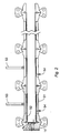
- FIG. 2 illustrates the injector 11 assembled to a tubular reactor assembly formed in sections 51 .
- Incorporated into the wall of the tubular reactor assembly are cooling water inlets 52 to provide boundary layer flow control at the reactor wall, and thereby prevent solids deposition on the reactor wall and help maintain the temperature in the reactor to within the optimal range for the desired reactions.
- Cooling water is supplied to these inlets 52 by feed pipes 53 spaced at intervals along the exterior of the reactor wall (one per wall section in this particular example). Examples of flow ducts within the wall itself and their arrangement along the internal wall surface for this type of cooling water introduction are found in United States Patent No. 5,387,398, issued February 7, 1995 on an application applied for on December 3, 1993. This patent is incorporated herein by reference for all legal purposes to be served thereby.
- the reactor assemble further contains wall taps 54 for pressure and temperature monitoring of the reaction.
- FIG. 3 shows a variation on the flow arrangement of FIGS. 1a and 1b , as well as an enlargement of the ports and one method of constructing them to direct the jets toward the reactor centerline.
- the fuel supply 61 is combined with the hot water supply 62 in a mixing chamber 63 in very close proximity to the injector face 64 .
- the fuel thus emerges from the injector face 64 as a single heated stream 65 at the centerline of the injector, ready for combustion upon contact with the oxidant.
- the oxidant jets 66 and waste material jets 67 emerge from circular port arrays encircling and converging toward the heated fuel stream 65 as in FIGS. 1a and 1b .
- the flow patterns formed by these converging streams are shown by their profiles 68, 69 .
- platelets 70 metal laminates. While platelet technology is well known, the following is a brief review of how it might be used in this present invention.
- Masks are first applied to individual metallic layers (or platelets), either by stencils or by photographic techniques.
- the platelets are then chemically etched through the masks, and the masks are then removed.
- Lamination of the platelets is then achieved by either diffusion-bonding, roll-bonding, brazing, or other conventional techniques for laminated metals.
- Diffusion-bonding involves hot-pressing the platelets together, using pressures typically in the range of 6.9 to 20.7 MPa (1000 to 3000 psi) and temperatures typically in the range of 455-540°C.
- the individual platelets themselves may be made of any material which can be formed into appropriately thin sheets, which is susceptible to etching and diffusion-bonding, and preferably which is also corrosion-resistant under the conditions encountered in super-critical water oxidation.
- the thickness of the platelets is not critical and may vary. Platelets having thicknesses less than about 0.025 inch (0.064 cm), or within the range of about 0.001 inch (0.0254 cm) to about 0.025 inch (0.064 cm), per platelet will most often be used. The aggregate of the platelets will most often be less than about 0.3 inch (0.762 cm) in thickness, more preferably about 0.03 inch (0.0762 cm) to about 0.3 inch (0.762 cm), and most preferably from about 0.05 inch (1.27 cm) to about 0.2 inch (0.51 cm).
- FIGS. 1a or 3 show an injector designed to supply a single fuel jet along the centerline of the tubular reactor with the jets of the other feed components arranged in concentric circles around the central fuel jet.
- This invention can also be applied in the use of multiple arrays distributed over the face of the injector, each array consisting of an arrangement similar to the array shown in FIGS. 1a or 3 .
- FIGS. 4a and 4b One such injector is shown in FIGS. 4a and 4b .
- the exposed face 75 of the injector 76 contains seven port arrays 77 , each one identical to the concentric circle arrangement shown in FIG. 3 .
- In only one 78 of the arrays is the fuel port aligned with the centerline 79 of the injector and the tubular reactor.
- the other six arrays are equally spaced around the central array 78 .
- An arrangement of this type with multiple fuel jets, each surrounded by jets of the remaining feed components, is particularly suitable for tubular reactors having an internal diameter of from about 6.0 inches (15.24 cm) to about 18.0 inches (45.72 cm).
- Single-array injectors of the types shown in FIGS. 1a, 1b, 2 and 3 are best suited to tubular reactors having an internal diameter of from about 1.0 inch (2.54 cm) to about 6.0 inch (15.24 cm).
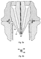
- FIGS. 5a and 5b A variation on the injector configuration appears in FIGS. 5a and 5b .
- the injector face 81 is conical in shape and thrust forward into the reaction space, placing the injection ports 82 inside an already flowing stream, and markedly reducing the risks and occurrences of recirculation in the reaction zone.
- Water fed through the side walls of the reactor for temperature control as in the preceding drawings, but higher water flows are fed through wall ports 83 located upstream of the injection ports 82 .
- the flow rates and temperatures of water fed through these wall ports is varied along the length of the tubular reactor in accordance with the functions served by the incoming water. At the upstream end, the incoming water can be hot enough to serve as a means of preheating the reaction environment and thereby lessening the heating burden on the incoming fuel stream.
- this injector contains a central fuel jet 84 surrounded by an annular oxidant stream 85 , and does not contain a series of hot water jets adjacent to the fuel jet to bring the fuel to combustion temperature. Heating of the fuel is instead achieved by preheating of the fuel prior to its entering the injector, or by the upstream water jets 83 positioned along the reactor wall.
- the waste material is fed through six jets 86 surrounding the annular oxidant stream 85.
- the annular oxidant stream 85 may be replaced by an array of oxidant ports directing their jets parallel to the central fuel jet.
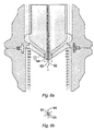
- FIGS. 6a and 6b A further variation is shown in FIGS. 6a and 6b , where the injector face 91 is conical in shape as in FIG. 5a , again placing the injection ports in an already moving stream of hot water.
- the number, shape and arrangement of the injection ports is similar to those of FIGS. 5a and 5b , with a central fuel port 92 , an annular oxidant port 93 surrounding the fuel port, and several waste material ports 94 arranged in a circular array concentric with the fuel port and oxidant port.
- the fuel port 92 is recessed relative to the opening of the annular oxygen port 93 , and all jets are directed parallel to the centerline of the tubular reactor.
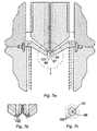
- the injector shown in FIGS. 7a, 7b and 7c differs from that of FIGS. 5a, 5b, 6a and 6b by both the fuel port 97 and the annular oxidant port 98 being recessed relative to both the waste material ports 99 and the coolant water ports 100 .
- the coolant water ports 100 in this design form a spray in diverging directions, thereby specifically providing protection of the surface of the injector from solids deposition and corrosion.
- the face surface 101 immediately surrounding the injection ports for the fuel, oxidant and waste material 97, 98, 99 is shaped as an inverted cone. This helps avoid recirculation and promotes a smooth flow in conformance with the shape of the ignition flame.
- the incoming streams are arranged to impinge upon each other in a multitude of combinations to enhance mixing.
- the various fuel ports are arranged in circular arrays around a centerline of the injector face. Closest to the centerline are four equally spaced fuel ports. The internal passages leading to these ports are oriented to cause the emerging streams to diverge and flow outward, away from the centerline.
- Surrounding the array of fuel ports are two circular arrays of ports, four ports in each array, each of which supplies hot water. All twelve ports are on a recessed planar surface at the center of the injector face.
- the eight hot water ports each direct hot water inward toward the centerline.
- the inner four hot water ports are positioned at angles intermediate to the angular positions of the fuel ports, with the result that the hot water streams from these ports flow between the fuel streams from the fuel ports, avoiding impingement of the fuel and hot water where these streams cross.
- the hot water streams themselves converge at a four-stream convergence point, located on the centerline.
- the outer four hot water ports by contrast, are radially aligned with the fuel ports and thereby impinge upon the fuel streams at two-stream convergence points. There are four such two-stream convergence points, and these points are not on the centerline.
- the fuel ports direct the fuel outward at an angle of 30° relative to the centerline, while the inner hot water ports direct hot water inward at the same angle, and the outer hot water ports direct hot water inward at an angle of 10°.
- the distances from the ports to the centerline are selected such that the locations of the impinging streams (both four-stream convergence and two-stream convergence) are all the same distance from the recessed surface of the injector face ( i.e. , in a common plane parallel to the recessed surface).
- a sloping conical wall surrounding the central recessed surface leads to a raised ring.
- An internal channel feeds oxidant to eight ports arranged in two concentric circles of four ports each -- an inner circle positioned on the sloping wall and an outer circle on the raised ring. All eight ports are radially aligned with the fuel ports.
- the ports of the inner circle direct their streams inward toward the centerline, where they converge and impinge upon the spray created by the impinging fuel and hot water streams.
- the ports of the outer circle direct their streams parallel to the centerline.
- On the planar surface of the raised ring are eight ports for the introduction of the waste material sought to be oxidized. These ports form a single circle concentric with the centerline, but are grouped into pairs along the circle.
- the ports are engineered to direct the two waste streams of each pair both toward each other (transverse to the radial direction of the injector) and toward the center. Each pair thus impinges first on itself and then on the oxidant stream formed by the outer oxidant ports.
- the planar surface of this recessed ring i.e ., the bottom of the trough) contains two circular arrays of twelve ports each, for introduction of cooling water.
- the ports of the inner circular array are angled inward toward the centerline of the injector to strike the inner sloping wall of the recessed ring, while the ports of the outer circular array are angled outward, away from the centerline, to strike the outer sloping wall of the recess. With this arrangement, all surfaces are flushed and washed continuously to prevent salt deposition and corrosion.
- the injectors of this invention can accommodate a variety of materials for SCWO, including different fuels, oxidants and waste materials.
- fuels are methane, methanol, ethanol, propanol and isopropanol.
- oxidants are air, oxygen, ozone and hydrogen peroxide. Isopropanol and oxygen are a preferred combination. Possible waste materials have been discussed above.
- the diameters of the ports may vary and are not critical to the invention. Typical diameters will generally range from about 0.008 inch (0.203 mm) to about 0.0125 inch (3,175 mm), and preferably from about 0.020 inch (0.508 mm) to about 0.080 inch (2.032 mm).
- the oxidant can either have an annular flow configuration surrounding the fuel jet, or be supplied as a series of jets arranged to surround the fuel jet, preferably in a circular array.
- the diameter of the annular port will generally be from about 0.008 inch (0.203 mm) to about 0.030 inch (0.762 mm).
- the oxidant When hot water jets are supplied to heat the fuel to ignition temperature, the oxidant will most conveniently be in the form of jets encircling the circle of hot water jets.
- the number of ports in each circular array can vary, but will generally range from 3 to 24, preferably from 6 to 12. For ports located a further distance from the fuel port, the number will often increase.
- the jet arrays are preferably circular for each series of jets of any one type of fluid
- the jets for cooling water where cooling water is supplied in this manner can form an array consisting of two or more circles or other patterned arrays extending over broad surface areas.
- the waste material ports will preferably form a circle having a diameter of from about 0.2 cm to about 2.0 cm, and most preferably from about 0.2 cm to about 1.0 cm.
- the oxidant ports will preferably form a circle having a diameter of from about 0.1 cm to about 1.5 cm, and most preferably from about 0.1 cm to about 0.7 cm.
- the injector is preferably constructed of a metallic material that is resistant to corrosion, such as Inconel-625 or steel.
- the injector face may be laminated with platinum.
Landscapes
- Chemical & Material Sciences (AREA)
- Organic Chemistry (AREA)
- Chemical Kinetics & Catalysis (AREA)
- Life Sciences & Earth Sciences (AREA)
- Hydrology & Water Resources (AREA)
- Engineering & Computer Science (AREA)
- Environmental & Geological Engineering (AREA)
- Water Supply & Treatment (AREA)
- Physical Or Chemical Processes And Apparatus (AREA)
- Treatment Of Water By Oxidation Or Reduction (AREA)
- Feeding, Discharge, Calcimining, Fusing, And Gas-Generation Devices (AREA)
- Nozzles (AREA)
Claims (9)
- Injektor bzw. Einspritzvorrichtung für einen superkritischen Wasser-Oxydations-Reaktor für flüssige, oxydierbare Stoffe, Injektor (11) genannt, welcher aufweist:eine Brennstoff-Auslassöffnung (41) und eine Versorgung (14, 15) für Brennstoff hierfür;eine Vorrichtung zum Aufheizen des Brennstoffs, welcher aus der Brennstoff-Auslassöffnung (41) kommt, auf wenigstens 375 °C;eine Vielzahl von Auslassöffnungen (44) für oxydierbare Stoffe, welche in einem Feld, welches die Vorrichtung zum Aufheizen des Brennstoffs umgibt, angeordnet sind, und eine Versorgung (20, 21) für flüssige oxydierbare Stoffe zu jeder dieser Auslassöffnungen (44) für oxydierbare Stoffe; undeine Vorrichtung zum Zuführen von Oxydationsmittel zwischen der Brennstoff-Auslassöffnung (41) und dem Feld von Auslassöffnungen (44) für oxydierbare Stoffe.
- Injektor nach Anspruch 1, bei welchem das Feld von Auslassöffnungen (44) für oxydierbare Stoffe als erstes Feld definiert wird, und bei welchem die Vorrichtung zum Zuführen des Oxydationsmittels aus einer Vielzahl von Oxydationsmittel-Auslassöffnungen (43) besteht, welche in einem zweiten Feld zwischen der Brennstoff-Auslassöffnung (41) und dem ersten Feld angeordnet sind.
- Injektor nach Anspruch 1, welcher ferner eine Vielzahl von Kühlwasser- Auslassöffnungen (45) aufweist, welche die Brennstoff-Auslassöffnung (41), die Auslassöffnungen (44) für oxydierbare Stoffe und die Vorrichtung (43) zum Zuführen des Oxydationsmittels umgeben.
- Injektor nach Anspruch 1, bei welchem das Feld von Auslassöffnungen (44) für oxydierbare Stoffe als ein erstes Feld definiert wird, und die Vorrichtung zum Zuführen des Oxydationsmittels eine Vielzahl von Oxydationsmittel-Auslassöffnungen (43) aufweist, welche in einem zweiten Feld zwischen der Brennstoff-Auslassöffnung (41) und dem ersten Feld angeordnet sind, wobei die Brennstoff-Auslassöffnung (41) so geformt ist, dass sie den Brennstoff in eine Richtung, welche als Achse definiert ist, führt und die Oxydationsmittel-Auslassöffnungen (43) so geformt sind, dass sie das Oxydationsmittel in Richtung dieser Achse führen und die Auslassöffnungen (44) für oxydierbare Stoffe so geformt sind, dass sie die oxydierbaren Stoffe in Richtungen parallel zu dieser Achse führen.
- Injektor nach Anspruch 1, bei welchem das Feld von Auslassöffnungen (44) für oxydierbare Stoffe als ein erstes Feld definiert wird, und die Vorrichtung zum Zuführen des Oxydationsmittels eine Vielzahl von Oxydationsmittel-Auslassöffnungen (43) aufweist, welche in einem zweiten Feld zwischen der Brennstoff-Auslassöffnung (41) und dem ersten Feld angeordnet sind, wobei die Brennstoff-Auslassöffnung (41) so geformt ist, dass sie den Brennstoff in eine Richtung, welche als Achse definiert ist, führt und die Oxydationsmittel-Auslassöffnungen (43) so geformt sind, dass sie das Oxydationsmittel in Richtung dieser Achse führen und die Auslassöffnungen (44) für oxydierbare Stoffe so geformt sind, dass sie die oxydierbaren Stoffe in Richtungen, welche diese Achse schneiden bzw. kreuzen, führen.
- Injektor nach Anspruch 1, bei welchem das Feld von Auslassöffnungen (44) für oxydierbare Stoffe als ein erstes Feld definiert wird, und die Vorrichtung zum Zuführen des Oxydationsmittels eine Vielzahl von Oxydationsmittel- Auslassöffnungen (43) aufweist, welche in einem zweiten Feld zwischen der Brennstoff-Auslassöffnung (41) und dem ersten Feld angeordnet sind, wobei die Brennstoff-Auslassöffnung (41) so geformt ist, dass sie den Brennstoff in eine Richtung, welche als Achse definiert ist, führt und die Oxydationsmittel-Auslassöffnungen (43) und die Auslassöffnungen (44) für oxydierbare Stoffe so geformt sind, dass sie das Oxydationsmittel und die oxydierbaren Stoffe in Richtungen, welche diese Achse schneiden bzw. kreuzen, führen.
- Injektor nach Anspruch 1, bei welchem das Feld von Auslassöffnungen (44) für oxydierbare Stoffe als ein erstes Feld definiert wird, und die Vorrichtung zum Zuführen des Oxydationsmittels eine Vielzahl von Oxydationsmittel- Auslassöffnungen (43) aufweist, welche in einem zweiten Feld zwischen der Brennstoff-Auslassöffnung (41) und dem ersten Feld angeordnet sind, wobei der Injektor (11) eine Vielzahl von Brennstoff-Auslassöffnungen (41) enthält, welche in einem dritten Feld angeordnet sind, und das erste und zweite Feld dieses dritte Feld umgeben.
- Injektor nach Anspruch 7, bei welchem das erste, zweite und dritte Feld im wesentlichen kreisförmig und konzentrisch sind, wodurch sie ein gemeinsames Zentrum definieren und der Injektor (11) eine Achse hat, welche diese gemeinsame Achse schneidet, und die Vorrichtung zum Aufheizen des Brennstoffs eine Vielzahl von Heißwasser-Auslassöffnungen (42) aufweist, welche in einem vierten Feld, welches das dritte Feld umgibt, angeordnet sind.
- Injektor nach Anspruch 1, welcher eine Vielzahl von Brennstoff-Auslassöffnungen (41) aufweist, welche von den Auslassöffnungen (44) für oxydierbare Stoffe, einer Vielzahl von Oxydationsmittel- Auslassöffnungen (43) und einer Vielzahl von Heißwasser-Auslassöffnungen (42) umgeben werden, wobei diese Auslassöffnungen Felder um eine gemeinsame zentrale Achse bilden, und bei dem diese Brennstoff-Auslassöffnungen (41) so geformt sind, um den Brennstoff in Richtungen zu führen, welche von der Achse weg verlaufen, und die Heißwasser-Auslassöffnungen (42) so geformt sind, um das Heißwasser in Richtungen zu führen, welche auf diese Achse hin verlaufen.
Applications Claiming Priority (3)
| Application Number | Priority Date | Filing Date | Title |
|---|---|---|---|
| US08/598,938 US5804066A (en) | 1996-02-08 | 1996-02-08 | Injector for SCWO reactor |
| US598938 | 1996-02-08 | ||
| PCT/US1997/001581 WO1997029050A1 (en) | 1996-02-08 | 1997-02-05 | Injector for scwo reactor |
Publications (2)
| Publication Number | Publication Date |
|---|---|
| EP0820423A1 EP0820423A1 (de) | 1998-01-28 |
| EP0820423B1 true EP0820423B1 (de) | 2001-10-24 |
Family
ID=24397552
Family Applications (1)
| Application Number | Title | Priority Date | Filing Date |
|---|---|---|---|
| EP97906457A Expired - Lifetime EP0820423B1 (de) | 1996-02-08 | 1997-02-05 | Einspritzvorrichtung für einen reaktor zur superkritischen flüssigkeitsoxidation |
Country Status (8)
| Country | Link |
|---|---|
| US (1) | US5804066A (de) |
| EP (1) | EP0820423B1 (de) |
| JP (1) | JP3282822B2 (de) |
| AT (1) | ATE207450T1 (de) |
| AU (1) | AU2114897A (de) |
| DE (1) | DE69707588T2 (de) |
| MX (1) | MX9707573A (de) |
| WO (1) | WO1997029050A1 (de) |
Families Citing this family (18)
| Publication number | Priority date | Publication date | Assignee | Title |
|---|---|---|---|---|
| JP3366820B2 (ja) * | 1997-02-19 | 2003-01-14 | 株式会社日立製作所 | 酸化処理方法とその装置及び反応容器 |
| SE518803C2 (sv) * | 1999-09-03 | 2002-11-26 | Chematur Eng Ab | Metod och reaktionssystem med högt tryck och hög temperatur som är lämpat för superkritisk vattenoxidation |
| WO2001096247A1 (en) * | 2000-06-12 | 2001-12-20 | Auburn University | Supercritical water oxidation with reduced corrosion and enhanced oxidation rate |
| US6475396B1 (en) * | 2000-11-14 | 2002-11-05 | Hydroprocessing, Llc | Apparatus and method for applying an oxidant in a hydrothermal oxidation process |
| ATE274995T1 (de) * | 2001-02-26 | 2004-09-15 | Dompe Spa | Apparat und methode zur bildung von mikro- und submikropartikeln |
| US6802179B2 (en) | 2002-12-02 | 2004-10-12 | Aerojet-General Corporation | Nozzle with spiral internal cooling channels |
| US6799417B2 (en) * | 2003-02-05 | 2004-10-05 | Aerojet-General Corporation | Diversion of combustion gas within a rocket engine to preheat fuel |
| US6832471B2 (en) * | 2003-03-12 | 2004-12-21 | Aerojet-General Corporation | Expander cycle rocket engine with staged combustion and heat exchange |
| FR2874513B1 (fr) * | 2004-08-25 | 2006-11-03 | Commissariat Energie Atomique | Dipositif et installation d'injection de matieres particulaires dans une enceinte et procede associe. |
| US20070163228A1 (en) * | 2006-01-19 | 2007-07-19 | United Technologies Corporation | Gas augmented rocket engine |
| SE0600982L (sv) * | 2006-05-02 | 2007-08-07 | Sandvik Intellectual Property | En komponent för anläggningar för superkritisk vattenoxidation, tillverkad av en austenitisk rostfri stållegering |
| US8568793B2 (en) | 2009-02-11 | 2013-10-29 | Hope Medical Enterprises, Inc. | Sodium nitrite-containing pharmaceutical compositions |
| ES2655883T5 (es) | 2009-07-08 | 2022-04-18 | Hope Medical Entpr Inc D B A Hope Pharmaceuticals | Composiciones farmacéuticas que contienen tiosulfato de sodio |
| WO2011159352A2 (en) * | 2010-06-16 | 2011-12-22 | Frontline Bio Energy,Llc | Producing low tar gases in a multi-stage gasifier |
| WO2015012806A1 (en) * | 2013-07-23 | 2015-01-29 | Empire Technology Development Llc | Reducing corrosion in a reactor system using fluid encasement |
| FR3027822A1 (fr) * | 2014-11-03 | 2016-05-06 | Guy Baret | Preparation de nanoparticules par traitement d'une solution en milieu hydrothermal |
| JP2019504757A (ja) | 2016-01-29 | 2019-02-21 | アルキメーデ・ソチエタ・ア・レスポンサビリタ・リミタータArchimede S.r.l. | 多機能反応器 |
| CN110790466B (zh) * | 2019-09-24 | 2020-08-18 | 西安交通大学 | 一种超临界水热火焰强化型超临界水氧化处理有机废弃物的系统及调控方法 |
Family Cites Families (21)
| Publication number | Priority date | Publication date | Assignee | Title |
|---|---|---|---|---|
| US4541796A (en) * | 1980-04-10 | 1985-09-17 | Union Carbide Corporation | Oxygen aspirator burner for firing a furnace |
| GB8311167D0 (en) * | 1983-04-25 | 1983-06-02 | Jenkins W N | Directed spray |
| US4792408A (en) * | 1987-04-13 | 1988-12-20 | James A. Titmas Associates Incorporated | Method and apparatus for enhancing chemical reactions at supercritical conditions |
| FR2648800B1 (fr) * | 1989-06-27 | 1991-10-18 | Inst Francais Du Petrole | Dispositif et procede de fabrication de gaz de synthese par combustion et son application |
| US5106513A (en) * | 1990-01-31 | 1992-04-21 | Modar, Inc. | Process for oxidation of materials in water at supercritical temperatures and subcritical pressures |
| US5232604A (en) * | 1990-01-31 | 1993-08-03 | Modar, Inc. | Process for the oxidation of materials in water at supercritical temperatures utilizing reaction rate enhancers |
| US5100560A (en) * | 1991-05-31 | 1992-03-31 | Abb Lummus Crest Inc. | Apparatus and method for supercritical water oxidation |
| US5252224A (en) * | 1991-06-28 | 1993-10-12 | Modell Development Corporation | Supercritical water oxidation process of organics with inorganics |
| AU2436192A (en) * | 1991-08-09 | 1993-03-02 | Board Of Regents, The University Of Texas System | High temperature wet oxidation using sintered separators |
| US5372725A (en) * | 1991-11-04 | 1994-12-13 | Halff; Albert H. | Method for separation and removal of impurities from liquids |
| US5425883A (en) * | 1991-11-04 | 1995-06-20 | Reid; Allen F. | Method for separation and removal of impurities from liquids |
| US5326540A (en) * | 1991-11-27 | 1994-07-05 | Philippe Chastagner | Containment system for supercritical water oxidation reactor |
| US5263849A (en) * | 1991-12-20 | 1993-11-23 | Hauck Manufacturing Company | High velocity burner, system and method |
| US5427764A (en) * | 1992-10-09 | 1995-06-27 | Rpc Waste Management Services, Inc. | Methods of controlling flow of fluids reacting at supercritical conditions |
| US5358646A (en) * | 1993-01-11 | 1994-10-25 | Board Of Regents, The University Of Texas System | Method and apparatus for multiple-stage and recycle wet oxidation |
| US5384051A (en) * | 1993-02-05 | 1995-01-24 | Mcginness; Thomas G. | Supercritical oxidation reactor |
| US5240619A (en) * | 1993-02-11 | 1993-08-31 | Zimpro Passavant Environmental Systems, Inc. | Two-stage subcritical-supercritical wet oxidation |
| US5386055A (en) * | 1993-08-11 | 1995-01-31 | The University Of Akron | Depolymerization process |
| US5387398A (en) * | 1993-12-03 | 1995-02-07 | Aerojet General Corporation | Supercritical water oxidation reactor with wall conduits for boundary flow control |
| US5597298A (en) * | 1994-12-13 | 1997-01-28 | Praxair Technology, Inc. | Laminar flow burner |
| US5492634A (en) * | 1995-02-02 | 1996-02-20 | Modar, Inc. | Method for treating halogenated hydrocarbons prior to hydrothermal oxidation |
-
1996
- 1996-02-08 US US08/598,938 patent/US5804066A/en not_active Expired - Fee Related
-
1997
- 1997-02-05 AT AT97906457T patent/ATE207450T1/de not_active IP Right Cessation
- 1997-02-05 MX MX9707573A patent/MX9707573A/es unknown
- 1997-02-05 AU AU21148/97A patent/AU2114897A/en not_active Abandoned
- 1997-02-05 DE DE69707588T patent/DE69707588T2/de not_active Expired - Fee Related
- 1997-02-05 JP JP52858997A patent/JP3282822B2/ja not_active Expired - Fee Related
- 1997-02-05 WO PCT/US1997/001581 patent/WO1997029050A1/en not_active Ceased
- 1997-02-05 EP EP97906457A patent/EP0820423B1/de not_active Expired - Lifetime
Also Published As
| Publication number | Publication date |
|---|---|
| DE69707588D1 (de) | 2001-11-29 |
| US5804066A (en) | 1998-09-08 |
| MX9707573A (es) | 1997-12-31 |
| JP3282822B2 (ja) | 2002-05-20 |
| EP0820423A1 (de) | 1998-01-28 |
| WO1997029050A1 (en) | 1997-08-14 |
| ATE207450T1 (de) | 2001-11-15 |
| HK1005369A1 (en) | 1999-01-08 |
| DE69707588T2 (de) | 2002-09-12 |
| AU2114897A (en) | 1997-08-28 |
Similar Documents
| Publication | Publication Date | Title |
|---|---|---|
| US5804066A (en) | Injector for SCWO reactor | |
| JP2002502303A (ja) | 超臨界水酸化反応器用インジェクタ | |
| FI90283C (fi) | Poltin, jossa on keskeinen happisuutin | |
| US4643890A (en) | Perforated reactor tube for a fluid wall reactor and method of forming a fluid wall | |
| EP0008842B1 (de) | Brenner für Brenngase unterschiedlichen Heizwertes mit Verbrennungsluftvorwärmung | |
| US5615833A (en) | External mixing type burner | |
| US5520334A (en) | Air and fuel mixing chamber for a tuneable high velocity thermal spray gun | |
| US20110000981A1 (en) | Injection head, mixing space and power unit | |
| JP7273025B2 (ja) | ガス化バーナ | |
| CN112742620B (zh) | 高速含氧空气燃料热喷涂装置 | |
| US4462318A (en) | Waste disposal | |
| US6860099B1 (en) | Liquid propellant tracing impingement injector | |
| EP0419198B1 (de) | Brenner zur Verbrennung von flüssigem Brennstoff | |
| KR890004944B1 (ko) | 산소절단 토오치(torch) | |
| US5950547A (en) | Combustor for burning a coal-gas mixture | |
| HK1005369B (en) | Injector for scwo reactor | |
| US4911363A (en) | Combustion head for feeding hot combustion gases and spray material to the inlet of the nozzle of a flame spray apparatus | |
| US4628835A (en) | Waste fluid incinerator having heat recovery means | |
| US20200166208A1 (en) | Burner | |
| JPH0225615A (ja) | 有孔ブロック体から成る合成ガス生成用バーナー | |
| KR102676559B1 (ko) | 플라즈마 저감용 플라즈마 스트림을 이송하는 노즐 및 관련 방법 | |
| EP2372240A1 (de) | Verbrennungsanlage | |
| EP0350032B1 (de) | Verbrennungsvorrichtung | |
| JP3105182B2 (ja) | ターボジェット式高温高速バーナ | |
| CN119957387B (zh) | 一种基于偏心式喷注单元的3d打印一体化喷注器 |
Legal Events
| Date | Code | Title | Description |
|---|---|---|---|
| PUAI | Public reference made under article 153(3) epc to a published international application that has entered the european phase |
Free format text: ORIGINAL CODE: 0009012 |
|
| 17P | Request for examination filed |
Effective date: 19971028 |
|
| AK | Designated contracting states |
Kind code of ref document: A1 Designated state(s): AT BE CH DE DK ES FI FR GB GR IE IT LI LU MC NL PT SE |
|
| AX | Request for extension of the european patent |
Free format text: AL PAYMENT 971028;LT PAYMENT 971028;LV PAYMENT 971028;RO PAYMENT 971028;SI PAYMENT 971028 |
|
| 17Q | First examination report despatched |
Effective date: 19991222 |
|
| GRAG | Despatch of communication of intention to grant |
Free format text: ORIGINAL CODE: EPIDOS AGRA |
|
| GRAG | Despatch of communication of intention to grant |
Free format text: ORIGINAL CODE: EPIDOS AGRA |
|
| GRAH | Despatch of communication of intention to grant a patent |
Free format text: ORIGINAL CODE: EPIDOS IGRA |
|
| GRAH | Despatch of communication of intention to grant a patent |
Free format text: ORIGINAL CODE: EPIDOS IGRA |
|
| GRAA | (expected) grant |
Free format text: ORIGINAL CODE: 0009210 |
|
| AK | Designated contracting states |
Kind code of ref document: B1 Designated state(s): AT BE CH DE DK ES FI FR GB GR IE IT LI LU MC NL PT SE |
|
| AX | Request for extension of the european patent |
Free format text: AL PAYMENT 19971028;LT PAYMENT 19971028;LV PAYMENT 19971028;RO PAYMENT 19971028;SI PAYMENT 19971028 |
|
| LTIE | Lt: invalidation of european patent or patent extension | ||
| PG25 | Lapsed in a contracting state [announced via postgrant information from national office to epo] |
Ref country code: NL Free format text: LAPSE BECAUSE OF FAILURE TO SUBMIT A TRANSLATION OF THE DESCRIPTION OR TO PAY THE FEE WITHIN THE PRESCRIBED TIME-LIMIT Effective date: 20011024 Ref country code: IT Free format text: LAPSE BECAUSE OF FAILURE TO SUBMIT A TRANSLATION OF THE DESCRIPTION OR TO PAY THE FEE WITHIN THE PRE;WARNING: LAPSES OF ITALIAN PATENTS WITH EFFECTIVE DATE BEFORE 2007 MAY HAVE OCCURRED AT ANY TIME BEFORE 2007. THE CORRECT EFFECTIVE DATE MAY BE DIFFERENT FROM THE ONE RECORDED.SCRIBED TIME-LIMIT Effective date: 20011024 Ref country code: FI Free format text: LAPSE BECAUSE OF FAILURE TO SUBMIT A TRANSLATION OF THE DESCRIPTION OR TO PAY THE FEE WITHIN THE PRESCRIBED TIME-LIMIT Effective date: 20011024 Ref country code: BE Free format text: LAPSE BECAUSE OF FAILURE TO SUBMIT A TRANSLATION OF THE DESCRIPTION OR TO PAY THE FEE WITHIN THE PRESCRIBED TIME-LIMIT Effective date: 20011024 Ref country code: AT Free format text: LAPSE BECAUSE OF FAILURE TO SUBMIT A TRANSLATION OF THE DESCRIPTION OR TO PAY THE FEE WITHIN THE PRESCRIBED TIME-LIMIT Effective date: 20011024 |
|
| REF | Corresponds to: |
Ref document number: 207450 Country of ref document: AT Date of ref document: 20011115 Kind code of ref document: T |
|
| REG | Reference to a national code |
Ref country code: CH Ref legal event code: EP |
|
| REG | Reference to a national code |
Ref country code: IE Ref legal event code: FG4D |
|
| REG | Reference to a national code |
Ref country code: CH Ref legal event code: NV Representative=s name: HEPP, WENGER & RYFFEL AG |
|
| REF | Corresponds to: |
Ref document number: 69707588 Country of ref document: DE Date of ref document: 20011129 |
|
| REG | Reference to a national code |
Ref country code: GB Ref legal event code: IF02 |
|
| PG25 | Lapsed in a contracting state [announced via postgrant information from national office to epo] |
Ref country code: PT Free format text: LAPSE BECAUSE OF FAILURE TO SUBMIT A TRANSLATION OF THE DESCRIPTION OR TO PAY THE FEE WITHIN THE PRESCRIBED TIME-LIMIT Effective date: 20020124 Ref country code: DK Free format text: LAPSE BECAUSE OF FAILURE TO SUBMIT A TRANSLATION OF THE DESCRIPTION OR TO PAY THE FEE WITHIN THE PRESCRIBED TIME-LIMIT Effective date: 20020124 |
|
| PG25 | Lapsed in a contracting state [announced via postgrant information from national office to epo] |
Ref country code: GR Free format text: LAPSE BECAUSE OF FAILURE TO SUBMIT A TRANSLATION OF THE DESCRIPTION OR TO PAY THE FEE WITHIN THE PRESCRIBED TIME-LIMIT Effective date: 20020125 |
|
| PG25 | Lapsed in a contracting state [announced via postgrant information from national office to epo] |
Ref country code: LU Free format text: LAPSE BECAUSE OF NON-PAYMENT OF DUE FEES Effective date: 20020205 Ref country code: IE Free format text: LAPSE BECAUSE OF NON-PAYMENT OF DUE FEES Effective date: 20020205 |
|
| PG25 | Lapsed in a contracting state [announced via postgrant information from national office to epo] |
Ref country code: SE Free format text: LAPSE BECAUSE OF NON-PAYMENT OF DUE FEES Effective date: 20020206 |
|
| ET | Fr: translation filed | ||
| PG25 | Lapsed in a contracting state [announced via postgrant information from national office to epo] |
Ref country code: LI Free format text: LAPSE BECAUSE OF NON-PAYMENT OF DUE FEES Effective date: 20020228 Ref country code: CH Free format text: LAPSE BECAUSE OF NON-PAYMENT OF DUE FEES Effective date: 20020228 |
|
| NLV1 | Nl: lapsed or annulled due to failure to fulfill the requirements of art. 29p and 29m of the patents act | ||
| PG25 | Lapsed in a contracting state [announced via postgrant information from national office to epo] |
Ref country code: ES Free format text: LAPSE BECAUSE OF FAILURE TO SUBMIT A TRANSLATION OF THE DESCRIPTION OR TO PAY THE FEE WITHIN THE PRESCRIBED TIME-LIMIT Effective date: 20020430 |
|
| PLBE | No opposition filed within time limit |
Free format text: ORIGINAL CODE: 0009261 |
|
| STAA | Information on the status of an ep patent application or granted ep patent |
Free format text: STATUS: NO OPPOSITION FILED WITHIN TIME LIMIT |
|
| PG25 | Lapsed in a contracting state [announced via postgrant information from national office to epo] |
Ref country code: MC Free format text: LAPSE BECAUSE OF NON-PAYMENT OF DUE FEES Effective date: 20020901 |
|
| EUG | Se: european patent has lapsed |
Ref document number: 97906457.3 |
|
| GBPC | Gb: european patent ceased through non-payment of renewal fee |
Effective date: 20020205 |
|
| REG | Reference to a national code |
Ref country code: CH Ref legal event code: PL |
|
| 26N | No opposition filed | ||
| REG | Reference to a national code |
Ref country code: FR Ref legal event code: ST |
|
| REG | Reference to a national code |
Ref country code: IE Ref legal event code: MM4A |
|
| PGFP | Annual fee paid to national office [announced via postgrant information from national office to epo] |
Ref country code: SE Payment date: 20030217 Year of fee payment: 7 |
|
| REG | Reference to a national code |
Ref country code: GB Ref legal event code: 728V |
|
| REG | Reference to a national code |
Ref country code: FR Ref legal event code: RN |
|
| REG | Reference to a national code |
Ref country code: FR Ref legal event code: FC |
|
| PGFP | Annual fee paid to national office [announced via postgrant information from national office to epo] |
Ref country code: FR Payment date: 20040202 Year of fee payment: 8 |
|
| PGFP | Annual fee paid to national office [announced via postgrant information from national office to epo] |
Ref country code: GB Payment date: 20040205 Year of fee payment: 8 |
|
| PGFP | Annual fee paid to national office [announced via postgrant information from national office to epo] |
Ref country code: DE Payment date: 20040227 Year of fee payment: 8 |
|
| REG | Reference to a national code |
Ref country code: GB Ref legal event code: 728Y |
|
| PG25 | Lapsed in a contracting state [announced via postgrant information from national office to epo] |
Ref country code: GB Free format text: LAPSE BECAUSE OF NON-PAYMENT OF DUE FEES Effective date: 20050205 |
|
| PG25 | Lapsed in a contracting state [announced via postgrant information from national office to epo] |
Ref country code: DE Free format text: LAPSE BECAUSE OF NON-PAYMENT OF DUE FEES Effective date: 20050901 |
|
| GBPC | Gb: european patent ceased through non-payment of renewal fee |
Effective date: 20050205 |
|
| PG25 | Lapsed in a contracting state [announced via postgrant information from national office to epo] |
Ref country code: FR Free format text: LAPSE BECAUSE OF NON-PAYMENT OF DUE FEES Effective date: 20051031 |
|
| REG | Reference to a national code |
Ref country code: FR Ref legal event code: ST Effective date: 20051031 |