EP0820558B1 - Systeme de commande a regulateur de surregime - Google Patents
Systeme de commande a regulateur de surregime Download PDFInfo
- Publication number
- EP0820558B1 EP0820558B1 EP96912691A EP96912691A EP0820558B1 EP 0820558 B1 EP0820558 B1 EP 0820558B1 EP 96912691 A EP96912691 A EP 96912691A EP 96912691 A EP96912691 A EP 96912691A EP 0820558 B1 EP0820558 B1 EP 0820558B1
- Authority
- EP
- European Patent Office
- Prior art keywords
- fluid pressure
- fuel
- valve assembly
- pressure
- integrator
- Prior art date
- Legal status (The legal status is an assumption and is not a legal conclusion. Google has not performed a legal analysis and makes no representation as to the accuracy of the status listed.)
- Expired - Lifetime
Links
- 239000012530 fluid Substances 0.000 claims description 112
- 239000000446 fuel Substances 0.000 claims description 102
- 238000009987 spinning Methods 0.000 claims description 30
- 238000002485 combustion reaction Methods 0.000 claims description 20
- 230000001105 regulatory effect Effects 0.000 claims description 8
- 230000008859 change Effects 0.000 claims description 7
- 230000009467 reduction Effects 0.000 claims description 5
- 230000000717 retained effect Effects 0.000 claims description 4
- 230000004044 response Effects 0.000 claims description 3
- 230000007423 decrease Effects 0.000 claims description 2
- 230000007613 environmental effect Effects 0.000 claims 1
- 239000007789 gas Substances 0.000 description 4
- 230000007246 mechanism Effects 0.000 description 4
- 235000014676 Phragmites communis Nutrition 0.000 description 2
- 230000008901 benefit Effects 0.000 description 2
- 230000004913 activation Effects 0.000 description 1
- 230000009286 beneficial effect Effects 0.000 description 1
- 239000003575 carbonaceous material Substances 0.000 description 1
- 230000008878 coupling Effects 0.000 description 1
- 238000010168 coupling process Methods 0.000 description 1
- 238000005859 coupling reaction Methods 0.000 description 1
- 238000006073 displacement reaction Methods 0.000 description 1
- 230000000694 effects Effects 0.000 description 1
- 230000007717 exclusion Effects 0.000 description 1
- 230000004907 flux Effects 0.000 description 1
- 239000002828 fuel tank Substances 0.000 description 1
- 238000002347 injection Methods 0.000 description 1
- 239000007924 injection Substances 0.000 description 1
- 239000000203 mixture Substances 0.000 description 1
- 230000002093 peripheral effect Effects 0.000 description 1
- 230000036316 preload Effects 0.000 description 1
Images


Classifications
-
- F—MECHANICAL ENGINEERING; LIGHTING; HEATING; WEAPONS; BLASTING
- F02—COMBUSTION ENGINES; HOT-GAS OR COMBUSTION-PRODUCT ENGINE PLANTS
- F02C—GAS-TURBINE PLANTS; AIR INTAKES FOR JET-PROPULSION PLANTS; CONTROLLING FUEL SUPPLY IN AIR-BREATHING JET-PROPULSION PLANTS
- F02C9/00—Controlling gas-turbine plants; Controlling fuel supply in air- breathing jet-propulsion plants
- F02C9/26—Control of fuel supply
- F02C9/28—Regulating systems responsive to plant or ambient parameters, e.g. temperature, pressure, rotor speed
-
- F—MECHANICAL ENGINEERING; LIGHTING; HEATING; WEAPONS; BLASTING
- F02—COMBUSTION ENGINES; HOT-GAS OR COMBUSTION-PRODUCT ENGINE PLANTS
- F02C—GAS-TURBINE PLANTS; AIR INTAKES FOR JET-PROPULSION PLANTS; CONTROLLING FUEL SUPPLY IN AIR-BREATHING JET-PROPULSION PLANTS
- F02C9/00—Controlling gas-turbine plants; Controlling fuel supply in air- breathing jet-propulsion plants
- F02C9/26—Control of fuel supply
- F02C9/38—Control of fuel supply characterised by throttling and returning of fuel to sump
-
- F—MECHANICAL ENGINEERING; LIGHTING; HEATING; WEAPONS; BLASTING
- F05—INDEXING SCHEMES RELATING TO ENGINES OR PUMPS IN VARIOUS SUBCLASSES OF CLASSES F01-F04
- F05D—INDEXING SCHEME FOR ASPECTS RELATING TO NON-POSITIVE-DISPLACEMENT MACHINES OR ENGINES, GAS-TURBINES OR JET-PROPULSION PLANTS
- F05D2270/00—Control
- F05D2270/01—Purpose of the control system
- F05D2270/02—Purpose of the control system to control rotational speed (n)
- F05D2270/021—Purpose of the control system to control rotational speed (n) to prevent overspeed
Definitions
- This invention relates to an overspeed governor control for use in a fuel management system to prevent damage to a turbine under certain rotational speed conditions.
- Every turbine engine has an optimum fuel to air ratio for the most effective and efficient thrust under varying operational conditions. It is common in a fuel management system to include a mechanical governor which functions in support of an electronically controlled fuel metering loop, consisting of an electrohydraulic servovalve that regulates control fluid to a fuel metering loop including a fuel metering valve with an electronic resolver attached for positional feedback, such as disclosed in U. S. Patent 4,245,462, through which fuel is supplied to a turbine.
- the metering loop receives an operational input from an electronic sensing and signal computer, which receives inputs from the resolver and other sensors relating to the operational conditions currently experienced by the turbine engine such as engine speed, power lever position, compressor inlet air temperature, altitude and other engine variables.
- Rotation of the turbine in an engine is basically a function of the fuel supplied from the fuel metering loop.
- Most turbines are designed to operate within a set rotational range but can rotate above this range for a short time period when additional thrust is needed to meet certain operational conditions. It has been observed that an electrical error signal supplied to the computer may under certain conditions result in more fuel being supplied to a combustion chamber for a longer time period than may be beneficial for the overall optimum operation of the turbine. Since the amount of fuel supplied to a combustion chamber essentially controls the turbine speed, in order to protect the turbine, mechanical governors such as disclosed in U.S. Patents 4,835,969 and 4,837,697 limit the amount of fuel supplied to a combustion chamber as a function of the rotational speed of the turbine.
- EP-A-278833 discloses a fuel system having a spinning spool valve assembly responsive to an operational force derived from the rotation of an engine.
- An advantage in the present invention resides in the exclusive use of a rotating spool valve assembly and an integrator valve assembly and the exclusion of a cam, related levers and valves in the mechanical governor of the prior art.
- a rotating flyweight mechanism responsive to the rotation of the turbine acts on and moves the spool valve assembly to communicate control fluid to the integrator valve assembly.
- the movement of the spool is opposed by first and second springs which sequentially allow the communication of control fluid to the integrator valve assembly which overrides controls for maintaining a fixed pressure differential across a fuel metering loop.
- the present invention comprises a fuel management system having a source of supply fuel with a substantially constant fluid pressure P s , said supply fuel being supplied to a fuel metering loop with a fluid pressure P 1 , said fuel metering loop being responsive to an input from an electronic computer for supplying operational fuel with a fluid pressure P 2 to a combustion chamber in an engine, a bypass valve responsive to said fluid pressure P 2 to control communication of a portion of said supply fuel having a fluid pressure P s to a return connected to said source of supply for maintaining a desired fluid pressure differential P 1 -P 2 across said fuel metering loop corresponding to said input from said electronic computer, a turbine responsive to the combustion of the operational fuel in said combustion chamber by rotating to drive a compressor in said engine and mechanical governor means responsive to a rotation of said turbine above a predetermined rotation for lowering the pressure differential P 1 -P 2 across a metering valve in said fuel metering loop by allowing operational fluid to flow to said return and thereby change the fluid pressure P 2 presented to said bypass valve to a fluid
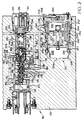
- Figure 1 is a schematic representation of a fuel management system for a turbine having a mechanical governor made according to the present invention to prevent an overspeed condition in the turbine.
- Figure 2 is an enlarged view of the mechanical governor of Figure 1.
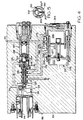
- Figure 3 is an enlarged view of the mechanical governor in a first mode of operation wherein the force developed in the flyweight as a result of rotation of the turbine has initially moved the spool valve assembly to communicate control fluid to the integrator valve assembly.
- Figure 4 is an enlarged view of the mechanical governor in a third mode of operation wherein the force developed in the flyweight as a result of rotation of the turbine corresponding to an overspeed rotation has moved the spool valve assembly to communicate control fluid to the integrator valve assembly and the integrator valve assembly has moved to reduce control fluid communicated to components that maintain a fixed pressure differential across the fuel metering loop resulting in a reduced pressure differential such that the fuel supplied to the combustion chamber is correspondingly reduced.
- Figure 5 is a sectional view taken along line 5-5 of Figure 3 showing the relationship between a bearing retainer and locating sleeve in the slidable spool valve assembly.
- a conventional gas turbine engine 10 shown in Figure 1 and similarly disclosed in U.S. Patent 3,835,969, has an air inlet 12, an air compressor 14, a plurality of combustion chambers 16, 16 n , a gas turbine 18 connected by as shaft 20 to drive compressor 14, and exhaust nozzle 22 through which products of combustion are expelled to the atmosphere.
- a plurality of fuel injection nozzles 24, only one of which is illustrated, connected to a fuel manifold 26 are adapted to inject metered pressurized fuel into the combustion chambers 16, 16 n where a resulting air fuel mixture is burned to generate hot motive gases that passes through turbine 18 to rotate compressor 14 and produce a thrust on exiting nozzle 22 to the surrounding atmosphere.
- a fuel management system 32 includes an electronic sensing and signal computer 36 which supplies a fuel metering valve 500 with an operation input and a hydromechanical governor control 34 to control the communication of fuel from an engine driven positive displacement pump 30.
- the fuel management system 32 supplies manifold 26 with fuel from tank 28 as a function of the fuel metering valve 500 and input supplied from computer 36.
- the electronic sensing and signal computer 36 receives electrical input signals representing selected variable conditions corresponding to the current operation of the engine 10 as, for example, engine speed N, compressor discharge air pressure P c , the position of the power lever 35, compressor inlet air temperature Ti, and other engine temperatures.
- the electrical input signals as sensed are compared electronically in computer 36 and an operational signal is thereafter supplied to operate the electrohydraulic servovalve 37 and resolver 48 to position fuel metering valve 50 to control the flow of fuel to manifold 26 by way of conduit 46.
- a portion of the supply fuel, having a fluid pressure P s , from pump 30 is diverted through conduit 61 to a servo regulator valves 60 and 62 to provide operational fluid having a substantially constant fluid pressure P c for operating the fuel management system while the supply fuel that is presented to the fuel metering valve 50 now has a fluid pressure P 1 .
- the restriction of flow of fuel through port 54 reduces the fluid pressure in the operational fuel such that the fluid pressure as supplied to manifold 26 has a fluid pressure of P 2 .
- a head sensor 64 and by pass valve 80 control the fluid pressure differential between P 1 and P 2 .
- the head sensor 64 includes a bellows 66 which receives the fluid pressure P 1 from the fuel metering valve 50 and acts on a movable member 68.
- Movable member 68 has a face 70 which is urged toward a seat 72 by an adjustable spring 74 and the fluid pressure P 2 which is communicated from conduit 46 by way of conduit 47 connected to shut off valve 76.
- the bypass valve 80 which is connected to the head sensor 64 has a sleeve 82 located in a bore 84 and connected to an integrator piston 86 which separates a P 2 P chamber 94 from a P x reference chamber 96.
- Chamber P 2 P is designed to receive fluid pressure P 2 which is communicated through a restrictor after passing through conduit 77, shut off valve 76 and conduit 47 while the reference chamber is designed to receive reference fluid pressure P x developed by head sensor 64.
- Sleeve 82 has a series of openings 88,88'...88n located adjacent an end thereof to control communication from bore 84 to port 92 in return conduit 95 connected to the fuel tank 28.
- sleeve 82 moves to provide communication fro bore 84 through openings 88, 88'...88 n to return 95 through port 92.
- the pressure differential between the fuel supply P 1 and the fluid pressure P 2 P acting on piston 100 move face 102 to define the number of openings 88, 88'...88 n through which fuel from the supply may flow to the return conduit 95.
- Sleeve 164 has a flange 166 which engages a shoulder 168 in the housing 132 for aligning a first communication groove and radial opening 170 with a port 172 in housing 132, a second communication groove and radial opening 174 with a port 176 in housing 132 and a third communication groove and radial opening 180 with a port 182.
- Port 172 is connected to receive regulated fluid pressure P c
- port 176 is connected by conduit 178 to integrator valve assembly 122 while port 182 is connected by conduit 184 to integrator valve assembly 122 and to head sensor 64 to receive fluid pressure P 2 P.
- Pins 202 maintains the bearing retainer member 204 in substantially the axial center of bore 130 such that radial forces induced by positioning orientation from sleeve 190 are substantially eliminated from any axial forces transmitted to the cylindrical spinning spool 128.
- Bearing retainer member 204 has a projection or spring guide 206 on one end and a cylindrical ring 208 on the other end. Cylindrical ring 208 is made of a carbon material and forms an engagement surface for the face 133 of the first end 136 of cylindrical spinning spool 128.
- a spring 210 which surrounds guide 206 is retained between the seat member 198 and bearing retainer member 204 for urging cylindrical ring 208 toward face 133 such that a gap 212 is formed between the end of the spring guide 206 and the seat member 198.
- a piston 214 which is positioned in sleeve 190 by an adjustment member 216, retains a spring 218 which urges seat member 198 into engagement with seat 196 to define the location of a first stop position associated with the first mode of operation of the spool valve assembly 120.
- a compensation arrangement 220 which includes bimetal washers 222 and piston 224 is located between adjustment member 216 and piston 214 to provide compensations for changes in temperature which may effect the operation of the accuracy of the slidable spool valve assembly 120.
- the integrator valve assembly 122 has a pressure responsive piston 226 located in a bore 228 for defining a first chamber 230 and a second chamber 232 within housing 132.
- Bore 228 has a port 234 connected to receive regulated fluid pressure P cr , a port 236 connected to the return 95 to be at the fluid pressure P cb of the body (P cb being slightly greater than the fluid pressure of the fluid pressure of the return in conduit 95), a port 238 connected to conduit 178 to receive fluid pressure P x derived from the control fluid pressure P c as defined by the position of the cylindrical spinning spool 128 within sleeve 164 and port 240 connected to conduit 184 connected to the head sensor 64 and port 182 of the slidable spool valve assembly 120 for receiving fluid pressure P 2 P.
- a sleeve 242 located in bore 228 has a flange 244 that is positioned against shoulder 246 by an end cap 248 attached to housing 132.
- End cap 248 has a series of radial openings 252, 252' through which port 238 is connected to the first chamber 230 while sleeve 242 has a first series of radial openings 254, 254' that connects port 240 with a groove 225 on the peripheral surface of piston 226, a second radial opening 256 and a third radial opening 258.
- Piston 226 has a plurality of radial openings 227, 227' that are alignable with a groove 257 connectable with radial opening 258 in sleeve 242.
- a sensor actuation member or magnet 260 has a carrier 262 which is attached to and moves with piston 226 within bore 228.
- a reed switch 264 provides computer 36 with information relating to the movement of piston 226 within bore 228.
- piston 226 With fluid pressure P x in chamber 230, piston 226 remains substantially in the position shown in Figure 3 as long as the force applied to the cylindrical spinning spool 128 is less than the spring force of spring 218, maintaining fluid pressure P x at the same fluid pressure as fluid pressure P cr .
- axial force developed by the movement of weight 123 about pin 124 from the rotation of shaft 114 reaches a predetermined axial force, typically such axial force is set to correspond to 106% of the optimum rotation of shaft 20 of turbine 10, spring 218 is overcome and cylindrical spinning spool 128 moves in a manner as illustrated in Figure 4.
- communication of control pressure P c from port 172 to port 176 and conduit 178 is less restricted such that fluid pressure P x increases to P x .
Landscapes
- Engineering & Computer Science (AREA)
- Chemical & Material Sciences (AREA)
- Combustion & Propulsion (AREA)
- Mechanical Engineering (AREA)
- General Engineering & Computer Science (AREA)
- Control Of Turbines (AREA)
Claims (8)
- Système de gestion de carburant (32) ayant une source de carburant d'alimentation (28, 30) à une pression de fluide substantiellement constante Ps, ledit carburant d'alimentation alimentant une boucle de dosage de carburant à une pression de fluide P1, ladite boucle de dosage de carburant réagissant à une entrée provenant d'un ordinateur électronique (36) pour fournir du carburant fonctionnel à une pression de fluide P2 à une chambre de combustion (16, 16n) dans un moteur (10), une soupape de dérivation (80) réagissant à ladite pression de fluide P2 pour commander la communication d'une portion dudit carburant d'alimentation à une pression de fluide Ps à un retour (95) connecté à ladite source d'alimentation (28, 30) pour maintenir une différence de pression de fluide souhaitée P1-P2 à travers ladite boucle de dosage de carburant, correspondant à ladite entrée provenant dudit ordinateur électronique (36), une turbine (18) réagissant à la combustion du carburant fonctionnel dans ladite chambre de combustion (16, 16n) en tournant de manière à entraíner un compresseur (14) dans ledit moteur (10), et un moyen de régulateur mécanique (116) réagissant à une rotation de ladite turbine (18) au-dessus d'une rotation prédéterminée pour abaisser la différence de pression P1-P2 à travers une soupape de dosage (50) dans ladite boucle de dosage de carburant en permettant au fluide fonctionnel de s'écouler jusqu'audit retour (95) et de changer ainsi la pression de fluide P2 régnant au niveau de ladite soupape de dérivation (80) en une pression de fluide P2P, du carburant d'alimentation supplémentaire étant communiqué audit retour (95) de telle sorte que la différence de pression souhaitée P1-P2 diminue de sorte que le carburant fourni à ladite chambre de combustion (16, 16n) soit réduit pour empêcher un état de surrégime dans ladite turbine (18) bien que l'entrée appliquée pour activer la boucle de dosage de carburant par ledit ordinateur électronique (36) ne change pas, ledit moyen de régulateur mécanique (116) comportant un ensemble de soupape à bague rotative cylindrique (120) situé dans un alésage (130) réagissant à une force fonctionnelle dérivée de la rotation de ladite turbine (18), où, dans un premier mode de fonctionnement, la communication de pression de commande Pc à un ensemble de soupape d'intégrateur (122) est inhibée par un premier ressort (210), ledit moyen de régulateur (116) étant caractérisé par un deuxième mode de fonctionnement comprenant la communication d'une pression de fluide fonctionnel Px, dérivée de la pression de commande Pc communiquée depuis l'ensemble de soupape à bague rotative (120), audit ensemble de soupape d'intégrateur (122) après que ladite force fonctionnelle surmonte ledit ressort (210) mais est restreinte par un deuxième ressort (218) et dans un troisième mode de fonctionnement, où ladite pression de fluide fonctionnel Px est augmentée après que la force fonctionnelle surmonte ledit deuxième ressort (218) et est fournie audit ensemble de soupape d'intégrateur (122) pour permettre à ladite pression de fluide P2P d'être abaissée en permettant l'écoulement à travers l'ensemble de soupape d'intégrateur (122) de telle sorte qu'une réduction ait lieu dans le carburant fourni à ladite chambre de combustion (16, 16n), et l'ensemble de soupape d'intégrateur (122) comportant un piston (226) situé dans un alésage (228) et connecté de manière à recevoir ladite pression de fluide Px, ledit piston (226) étant positionné à l'intérieur dudit alésage (228) en fonction d'une différence de pression développée à travers le piston (226) entre ladite pression de fluide Px et une pression de commande régulée Pcr, ledit piston (226) se déplaçant en réponse audit troisième mode de fonctionnement pour surmonter ladite pression de commande régulée et permettre à la fois à la pression de fluide Px et à la pression de fluide P2P d'être communiquées simultanément au retour (95), ladite communication de pression de fluide P2P audit retour (95) étant restreinte pour limiter l'écoulement de fluide à la pression de fluide P2P depuis le système (32).
- Système de gestion de carburant selon la revendication 1, caractérisé en ce que dans ledit troisième mode de fonctionnement, un chemin d'écoulement de communication est prévu à travers ledit ensemble de soupape à bague rotative cylindrique (120).
- Système de gestion de carburant selon la revendication 2, caractérisé en ce que lesdits premier et deuxième ressorts (210, 218) sont connectés par des moyens de manchon (190) et des moyens d'ajustement (194, 195, 214, 216) pour établir les premier, deuxième et troisième modes de fonctionnement dudit ensemble de soupape à bague coulissante (120).
- Système de gestion de carburant selon la revendication 3, caractérisé en ce que le système (32) comporte en outre un organe de retenue de support (204) situé entre le premier ressort (210) et ledit ensemble de soupape à bague rotative cylindrique (120), ledit organe de retenue de support (204) se déplaçant axialement dans ledit alésage (228) pour limiter le mouvement dudit ensemble de soupape à bague rotative cylindrique (120) pour définir une position pour l'ensemble de soupape à bague rotative cylindrique (120) afin d'amorcer la communication de pression de fluide Px audit ensemble de soupape d'intégrateur (122).
- Système de gestion de carburant selon la revendication 4, caractérisé en ce que lesdits moyens d'ajustement (194, 195, 214, 216) comportent un moyen de compensation de température (220, 222) pour maintenir les premier, deuxième et troisième modes de fonctionnement substantiellement uniformes lorsqu'ils sont soumis à diverses conditions de température environnementales.
- Système de gestion de carburant selon la revendication 3, caractérisé en ce que ledit ensemble de soupape à bague rotative cylindrique (120) comporte un organe cylindrique (128) avec des méplats (138, 140, 142, 144) et des rainures (146, 148, 150) qui sont associés à des orifices correspondants (156, 162) dans un boítier (132) pour communiquer la pression de fluide Px audit ensemble de soupape d'intégrateur (122) et ladite pression de fluide P2P au retour (95).
- Système de gestion de carburant selon la revendication 6, caractérisé en ce que ledit ensemble de soupape d'intégrateur (122) comporte un moyen de détection de position (260, 264) pour fournir audit ordinateur électronique (36) des informations concernant le deuxième mode de fonctionnement dudit ensemble de soupape à bague rotative cylindrique (120).
- Système de gestion de carburant selon la revendication 4, caractérisé en ce que ledit organe de retenue de support (204) comporte une pluralité de broches (202) qui sont retenues dans des fentes (192) dans ledit moyen de manchon (190) de sorte que toute force radiale induite par l'orientation de position dudit moyen de manchon (190) soit substantiellement éliminée de toute force axiale transmise audit ensemble de soupape à bague rotative cylindrique (120).
Applications Claiming Priority (3)
| Application Number | Priority Date | Filing Date | Title |
|---|---|---|---|
| US419338 | 1995-04-10 | ||
| US08/419,338 US5579632A (en) | 1995-04-10 | 1995-04-10 | Overspeed governor control system |
| PCT/US1996/005012 WO1996032577A1 (fr) | 1995-04-10 | 1996-04-10 | Systeme de commande a regulateur de surregime |
Publications (2)
| Publication Number | Publication Date |
|---|---|
| EP0820558A1 EP0820558A1 (fr) | 1998-01-28 |
| EP0820558B1 true EP0820558B1 (fr) | 2001-07-18 |
Family
ID=23661822
Family Applications (1)
| Application Number | Title | Priority Date | Filing Date |
|---|---|---|---|
| EP96912691A Expired - Lifetime EP0820558B1 (fr) | 1995-04-10 | 1996-04-10 | Systeme de commande a regulateur de surregime |
Country Status (5)
| Country | Link |
|---|---|
| US (1) | US5579632A (fr) |
| EP (1) | EP0820558B1 (fr) |
| JP (1) | JPH11503804A (fr) |
| DE (1) | DE69613972T2 (fr) |
| WO (1) | WO1996032577A1 (fr) |
Families Citing this family (7)
| Publication number | Priority date | Publication date | Assignee | Title |
|---|---|---|---|---|
| EP1045964B1 (fr) | 1998-01-08 | 2012-08-08 | United Technologies Corporation | Systeme de pressurisation hydraulique a deux niveaux |
| US6321525B1 (en) | 2000-02-03 | 2001-11-27 | Rolls-Royce Corporation | Overspeed detection techniques for gas turbine engine |
| US6915639B1 (en) * | 2000-10-13 | 2005-07-12 | General Electric Company | Method and apparatus for gas turbine over-speed protection |
| FR2825120B1 (fr) * | 2001-05-25 | 2003-12-12 | Snecma Moteurs | Doseur a 2 sorties integrees |
| GB0118214D0 (en) * | 2001-07-26 | 2001-09-19 | Lucas Industries Ltd | Fuel system |
| US7437871B2 (en) | 2002-05-31 | 2008-10-21 | General Electric Company | Automatic engine protection system for use when electronic parts of a control system are exposed to overtemperature conditions |
| GR1009969B (el) * | 2019-02-11 | 2021-04-06 | Λαμπρος Διαμαντη Σαρμπανης | Μηχανισμος προστασιας υπερταχυνσης για ρυθμιστη στροφων σε μηχανες εσωτερικης καυσης, στροβιλους |
Family Cites Families (12)
| Publication number | Priority date | Publication date | Assignee | Title |
|---|---|---|---|---|
| US3049139A (en) * | 1956-11-08 | 1962-08-14 | Bendix Corp | Control apparatus |
| GB1369653A (en) * | 1971-01-06 | 1974-10-09 | Lucas Industries Ltd | Fuel control system for gas turbine engine |
| US4245462A (en) * | 1978-11-29 | 1981-01-20 | The Bendix Corporation | Starting system for a turbine engine |
| GB2092677B (en) * | 1981-02-11 | 1984-03-21 | Rolls Royce | Fuel control system for a gas turbine engine |
| US4602479A (en) * | 1985-06-12 | 1986-07-29 | United Technologies Corporation | Fuel control |
| FR2594488B1 (fr) * | 1986-02-19 | 1988-05-06 | Snecma | Amelioration aux regulateurs hydromecaniques |
| US4716723A (en) * | 1986-09-05 | 1988-01-05 | Woodward Governor Company | Fuel controls for gas turbine engines |
| GB2197909B (en) * | 1986-11-26 | 1991-07-31 | Rolls Royce Plc | Fuel control system for gas turbine aeroengine overspeed protection. |
| FR2610040B1 (fr) * | 1987-01-28 | 1991-02-08 | Snecma | Sous-ensemble modulaire de regulation a detecteur de perte de charge et limiteur de survitesse integres |
| US4760662A (en) * | 1987-04-24 | 1988-08-02 | United Technologies Corporation | Hybrid fuel metering system |
| US4837697A (en) * | 1987-07-31 | 1989-06-06 | Allied-Signal Inc. | Overspeed governor for an electronic controlled fuel system |
| US4835969A (en) * | 1987-10-05 | 1989-06-06 | Allied-Signal Inc. | Error detection means for an overspeed governor |
-
1995
- 1995-04-10 US US08/419,338 patent/US5579632A/en not_active Expired - Lifetime
-
1996
- 1996-04-10 JP JP8531183A patent/JPH11503804A/ja not_active Abandoned
- 1996-04-10 DE DE69613972T patent/DE69613972T2/de not_active Expired - Fee Related
- 1996-04-10 WO PCT/US1996/005012 patent/WO1996032577A1/fr not_active Ceased
- 1996-04-10 EP EP96912691A patent/EP0820558B1/fr not_active Expired - Lifetime
Also Published As
| Publication number | Publication date |
|---|---|
| WO1996032577A1 (fr) | 1996-10-17 |
| DE69613972T2 (de) | 2002-04-04 |
| DE69613972D1 (de) | 2001-08-23 |
| EP0820558A1 (fr) | 1998-01-28 |
| JPH11503804A (ja) | 1999-03-30 |
| US5579632A (en) | 1996-12-03 |
Similar Documents
| Publication | Publication Date | Title |
|---|---|---|
| CA1220727A (fr) | Regulateur du jeu entre aubes et enveloppe de turbine | |
| US6981359B2 (en) | Centrifugal pump fuel system and method for gas turbine engine | |
| CA1274698A (fr) | Regulateur de survitesse pour systeme de carburant a commande electronique | |
| EP0037786B1 (fr) | Dispositif de contrôle de carburant | |
| EP0820558B1 (fr) | Systeme de commande a regulateur de surregime | |
| US4368618A (en) | Manually operated metering valve for a fuel control | |
| US3508395A (en) | Control system for motor vehicle type gas turbine engine | |
| CA1204601A (fr) | Regulateur d'admission du carburant pour turbomoteur a gaz | |
| US3996964A (en) | Control apparatus particularly for a plurality of compressor bleed valves of a gas turbine engine | |
| US4078378A (en) | Automotive gas turbine fuel control | |
| US3953967A (en) | Servoed throttle valve for fuel controls | |
| US3994617A (en) | Control apparatus particularly for a plurality of compressor bleed valves of a gas turbine engine | |
| CA1177144A (fr) | Appareil de regulation de combustible pour moteur de turbine au gaz | |
| US3899879A (en) | Turbine engine fuel control | |
| US3712055A (en) | Fuel control | |
| CA1284751C (fr) | Organe detecteur d'erreur du fonctionnement d'un regulateur de regime pour prevenir les survitesses | |
| US4517796A (en) | Power lever apparatus for a turbine engine | |
| US4000607A (en) | Fluid control valve and method | |
| GB2288004A (en) | Fuel injection regulating valve for a turbomachine | |
| US3958414A (en) | Control valve arrangement for gas turbine engine fuel supply system | |
| CA1215550A (fr) | Mecanisme de commande actionne par pression | |
| GB1352410A (en) | Gas turbine engine fuel supply control system | |
| GB1491212A (en) | Fuel control system for gas turbine engine | |
| Gold | Automotive gas turbine fuel control |
Legal Events
| Date | Code | Title | Description |
|---|---|---|---|
| PUAI | Public reference made under article 153(3) epc to a published international application that has entered the european phase |
Free format text: ORIGINAL CODE: 0009012 |
|
| 17P | Request for examination filed |
Effective date: 19970915 |
|
| AK | Designated contracting states |
Kind code of ref document: A1 Designated state(s): DE FR GB |
|
| RAP1 | Party data changed (applicant data changed or rights of an application transferred) |
Owner name: HONEYWELL INTERNATIONAL INC. |
|
| GRAG | Despatch of communication of intention to grant |
Free format text: ORIGINAL CODE: EPIDOS AGRA |
|
| 17Q | First examination report despatched |
Effective date: 20001026 |
|
| GRAG | Despatch of communication of intention to grant |
Free format text: ORIGINAL CODE: EPIDOS AGRA |
|
| GRAH | Despatch of communication of intention to grant a patent |
Free format text: ORIGINAL CODE: EPIDOS IGRA |
|
| GRAH | Despatch of communication of intention to grant a patent |
Free format text: ORIGINAL CODE: EPIDOS IGRA |
|
| GRAA | (expected) grant |
Free format text: ORIGINAL CODE: 0009210 |
|
| AK | Designated contracting states |
Kind code of ref document: B1 Designated state(s): DE FR GB |
|
| REF | Corresponds to: |
Ref document number: 69613972 Country of ref document: DE Date of ref document: 20010823 |
|
| ET | Fr: translation filed | ||
| REG | Reference to a national code |
Ref country code: GB Ref legal event code: IF02 |
|
| PLBE | No opposition filed within time limit |
Free format text: ORIGINAL CODE: 0009261 |
|
| STAA | Information on the status of an ep patent application or granted ep patent |
Free format text: STATUS: NO OPPOSITION FILED WITHIN TIME LIMIT |
|
| 26N | No opposition filed | ||
| PGFP | Annual fee paid to national office [announced via postgrant information from national office to epo] |
Ref country code: DE Payment date: 20040430 Year of fee payment: 9 |
|
| PG25 | Lapsed in a contracting state [announced via postgrant information from national office to epo] |
Ref country code: DE Free format text: LAPSE BECAUSE OF NON-PAYMENT OF DUE FEES Effective date: 20051101 |
|
| PGFP | Annual fee paid to national office [announced via postgrant information from national office to epo] |
Ref country code: GB Payment date: 20090312 Year of fee payment: 14 |
|
| PGFP | Annual fee paid to national office [announced via postgrant information from national office to epo] |
Ref country code: FR Payment date: 20090406 Year of fee payment: 14 |
|
| GBPC | Gb: european patent ceased through non-payment of renewal fee |
Effective date: 20100410 |
|
| REG | Reference to a national code |
Ref country code: FR Ref legal event code: ST Effective date: 20101230 |
|
| PG25 | Lapsed in a contracting state [announced via postgrant information from national office to epo] |
Ref country code: GB Free format text: LAPSE BECAUSE OF NON-PAYMENT OF DUE FEES Effective date: 20100410 |
|
| PG25 | Lapsed in a contracting state [announced via postgrant information from national office to epo] |
Ref country code: FR Free format text: LAPSE BECAUSE OF NON-PAYMENT OF DUE FEES Effective date: 20100430 |