EP0820687A1 - Perfectionnements pour et en relation avec charrues agricoles - Google Patents
Perfectionnements pour et en relation avec charrues agricoles Download PDFInfo
- Publication number
- EP0820687A1 EP0820687A1 EP97305510A EP97305510A EP0820687A1 EP 0820687 A1 EP0820687 A1 EP 0820687A1 EP 97305510 A EP97305510 A EP 97305510A EP 97305510 A EP97305510 A EP 97305510A EP 0820687 A1 EP0820687 A1 EP 0820687A1
- Authority
- EP
- European Patent Office
- Prior art keywords
- ploughing
- plough
- soil
- disc
- displacing
- Prior art date
- Legal status (The legal status is an assumption and is not a legal conclusion. Google has not performed a legal analysis and makes no representation as to the accuracy of the status listed.)
- Withdrawn
Links
Images


Classifications
-
- A—HUMAN NECESSITIES
- A01—AGRICULTURE; FORESTRY; ANIMAL HUSBANDRY; HUNTING; TRAPPING; FISHING
- A01B—SOIL WORKING IN AGRICULTURE OR FORESTRY; PARTS, DETAILS, OR ACCESSORIES OF AGRICULTURAL MACHINES OR IMPLEMENTS, IN GENERAL
- A01B5/00—Ploughs with rolling non-driven tools, e.g. discs
- A01B5/10—Ploughs with rolling non-driven tools, e.g. discs mounted or partly-mounted on tractors
- A01B5/14—Alternating ploughs
-
- A—HUMAN NECESSITIES
- A01—AGRICULTURE; FORESTRY; ANIMAL HUSBANDRY; HUNTING; TRAPPING; FISHING
- A01B—SOIL WORKING IN AGRICULTURE OR FORESTRY; PARTS, DETAILS, OR ACCESSORIES OF AGRICULTURAL MACHINES OR IMPLEMENTS, IN GENERAL
- A01B17/00—Ploughs with special additional arrangements, e.g. means for putting manure under the soil, clod-crushers
Definitions
- This invention relates to agricultural ploughs. In some countries there are bans on straw and stubble burning. There is, consequently, a need for arable farmers to be able to incorporate straw and other debris into the ground.
- Mouldboard ploughs are of limited use for this purpose in the case of heavy land. When the ground is hard and dry penetration is a problem and wear of the soil-engaging parts of the plough is excessive. When the land is wet the mouldboard plough causes an unacceptable level of soil compaction.
- a disc plough is disclosed in the applicant's earlier WO-A-92/17050.
- This earlier plough includes a frame beam which, in use, extends diagonally with respect to the direction of ploughing. The diagonal direction in which the beam extends relative to the direction of ploughing can be changed so as to allow the plough to switch between right- and left-hand ploughing.
- Individual plough units are connected to the beam by pivot connections to trail from the beam.
- Each plough unit includes a ploughing disc. Each disc is mounted for rotation about a substantially horizontal shaft which itself is pivotable about its end remote from the plough disc so as to enable reversal of the inclination of the ploughing disc relative to the direction of travel, to change the arrangement between right- and left-hand ploughing.
- a plough comprising:
- the hereinafter described and first illustrated embodiment of a reversible plough in accordance with the present invention is lighter and has a simpler, and thus less costly, construction than the plough disclosed in WO-A-92/17050.
- the plough also has fewer wearing parts and is lighter in weight.
- the plough of the present invention is reversible in so far as it is able to be used in both right- and left-handed ploughing by inverting the frame.
- the rotatable ploughing discs are able to move relative to the frame so that when the plough is in its left-handed ploughing mode each disc is associated with a left-handed soil displacing unit and when the frame is inverted to switch the plough to its right-handed ploughing mode these same discs are movable each to be used with a right-handed soil displacing unit.
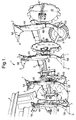
- Figure 1 shows an embodiment of a plough 1 in accordance with the present invention mounted on the rear of a tractor 2; only the back right-hand corner of the tractor 2 is shown.
- the first illustrated embodiment of a plough 1 comprises a frame 3.
- the frame 3 comprises a main beam which extends rearwardly from the tractor and, in use, extends diagonally across the direction of ploughing PD.
- the frame 3 has four upwardly extending legs 4A and four downwardly extending legs 4B.
- each upwardly extending leg 4A is, in fact, continuous with a downwardly extending leg 4B.
- the plough is shown in Figure 1 as having four pairs of legs 4A, 4B the invention is applicable to ploughs with other numbers of legs.
- Soil displacing units 5A, 5B are mounted on the ends of the legs 4A, 4B of each pair of legs.
- the upwardly extending legs 4A are shown as being provided with right-handed soil displacing units 5A meaning that they will, in use, displace soil to the right relative to the forward ploughing direction.
- the downwardly extending legs 4B are provided with left-handed soil displacing units 5B for, in use, displacing soil to the left, relative to the forward ploughing direction.
- the frame 3 is shown in Fig. 1 configured for left-handed ploughing as the left-handed soil displacing units 5B are positioned so as to engage the ground when the frame 3 is lowered on the tractor hitch.
- the frame 3 is selectively invertible about an inversion axis IA (marked in Figures 2, 4 and 5) generally parallel to the intended ploughing direction, in the manner of the frames of known mouldboard ploughs.
- the main plough frame 3, legs 4A, 4B and inverting mechanism may be of the same basic steel frame design as used for conventional mouldboard ploughs.
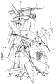
- the soil-displacing units comprise mouldboard-type bodies, as most readily seen in Figures 2 and 3 which show the leading right-handed soil-displacing unit 5A; in Figure 2 most of the following soil-displacing unit 5A is also visible, offset to the left relative to the intended ploughing direction PD.
- the mouldboard-type bodies are shaped to skim off upwardly from the surface of the ground a sliver of soil, together with any stubble thereon, and to invert the sliver as it is moved laterally into an adjacent furrow. Having slivers rise up the mouldboard shapes of the bodies is preferred to simply pushing the soil sideways at ground level without inverting it.
- Each soil-displacing unit 5A, 5B advantageously includes a leading point 6 for, in use, engaging and cutting the ground. This point generates a draft holding the plough down.
- each soil-displacing unit includes a landside 7 extending rearwardly from its respective point 6, parallel to the ploughing direction PD. These landsides help to resist transverse movement of the plough. Alternatively, or additionally, a large landside (not shown) may be provided at the trailing end of the frame 3, independently of a soil-displacing unit, to extend into the ground to locate the plough laterally.
- the first illustrated embodiment of plough also comprises four rotatable ploughing discs 8, each disc being associated with a pair of oppositely-handed soil displacing units 5A, 5B.
- each ploughing disc 8 is pivotally mounted to the frame 3 via a swing arm 9, as is most clearly shown in Figure 3.
- Each disc 8 is movable relative to the frame 3 and its associated soil-displacing units 5A, 5B to switch between two operative positions, one such position corresponding with right-handed ploughing (as shown in Figures 2-4) and the other corresponding with left-handed ploughing (as shown in Figures 1 and 5).
- a ploughing disc 8 will, in use, be in ploughing engagement with the soil behind whichever unit of its associated pair of oppositely handed soil-displacing units 5A, 5B is in engagement with the ground.
- each swing arm 9 includes a bracket 10 welded to the main diagonal member of the frame 3.
- the bracket 10 triangulates a section of bar 11 welded to both the bracket 10 and to the side wall of the main frame member.
- a collar 12 is rotatably mounted on the bar 11.
- One end of the main tube section which forms swing arm 9 is welded to the collar 12.
- the opposite end of the arm 9 is provided with a bearing and stub axle assembly 13 on which a ploughing disc 8 is mounted to rotate, in use, about axis of rotation 14.
- the pivotal connection is advantageously made of steel, as is the swing arm 9 and ploughing disc 8.
- the swing arm 9 is capable of swinging relative to the frame 3 and the soil-displacing units 5A, 5B about a pivot axis 15, to switch the ploughing disc 8 between its two operative positions.
- the ploughing direction PD is marked in both Figures 2-5.
- the pivot axis 15 is generally horizontal in use of the plough and is angled in the horizontal plane relative to the intended ploughing direction PD.
- the angle of intersection ⁇ between the pivot axis 15 and the ploughing direction PD is in the range of approximately 25-70°, preferably about 40° - see Figures 2 and 4. In the first illustrated embodiment this angle ⁇ is linked to the angle of the ploughing disc 8 to the ploughing direction PD, as discussed below.
- the axes of rotation 14 for the four different ploughing discs 8 are all generally parallel to one another.
- the four pivot axes 15 are advantageously all generally parallel to one another.
- each ploughing disc 8 is horizontal, so that each ploughing disc 8 is in use generally perpendicular to the ground, albeit inclined relative to the intended ploughing direction PD.
- the discs 8 may, however, be canted over slightly (not shown) so as no longer to be generally perpendicular to the ground. This would have the effect of raising the right hand end of the pivot axis 14 (when viewed from the position of viewing in Figure 3).
- each soil-displacing unit 5A is arranged to extend into the ground by approximately 5-15 centimetres.
- Each ploughing disc 8 extends into the ground by a greater amount, for example 15-25 centimetres.
- each soil-displacing unit 5A and that of the rotatable ploughing disc 8 positioned therebehind are inclined to the intended ploughing direction PD.
- the soil-displacing units 5 are inclined relative to the ploughing direction PD by approximately the same amount as their respective ploughing discs 8.
- the rearwardly facing face of the central portion of each ploughing disc 8 in use advantageously makes an angle X with the intended ploughing direction PD of approximately 20-60°, preferably about 35° as shown.
- the legs 4 are spaced apart down the length of the beam 3. Because the beam 3 extends diagonally with respect to the ploughing direction PD the legs have a lateral spacing Y across the ploughing direction - see Figure 4. This lateral spacing Y may, for example, be of the order of 30-45 cm.
- the disc 8 has to be movable with respect to the frame 3 and its associated pair of soil-displacing units 5. In the first illustrated embodiment this movement of the ploughing discs 8 from their operative right-handed ploughing positions to their operative left-handed ploughing positions is achieved via pivoting.
- the swing arms 9 Upon inverting the frame by turning it through a half-turn about axis IA generally parallel to ploughing direction PD, the swing arms 9 are pivoted around their respective pivot axes 15 to switch each of the tilling discs from being in its operative position behind its associated right-handed soil-displacing unit (as shown in Figures 2-4) to its alternative operative position behind its associated left-handed soil-displacing unit (as shown in Figures 1 and 5).
- the action of inverting the frame 3 from the position shown in Figures 2-4 is thus coordinated with each ploughing disc 8 switching from being configured for right-hand ploughing, i.e. so as to displace soil to the right, to become configured for left-handed ploughing, i.e. so as to move soil to the left.
- Gravity may be relied upon to cause the swing arms 9 and discs 8 to move from one operative position to the other operative position upon inverting the frame 3.
- some sort of bump stop (not shown) and/or damper is provided to reduce the risk of damage to the plough upon a swing arm 9 and disc 8 moving from one operative position to arrive suddenly at its other operative position.
- pivotal movement of the swing arm 9 may be driven, for example by using a hydraulic or pneumatic ram.
- any bump stop is adjustable so as to allow for change of the arc, around pivot axis 15, through which the swing arm 9 is movable.
- the location of a disc's operative position relative to its soil-displacing unit 5 may be varied slightly to change the depth to which the disc 8 will extend into the soil in use.
- means may be provided for locking the swing arms 9 relative to the frame 3 when the discs 8 are in their operative positions to resist any tendency for the discs 8 in use to ride up out of the ground by pivoting on their swing arms 9.
- the ploughing discs 8 have a planar central portion and an inclined flange portion extending from the periphery of the central portion, with an abrupt transition being provided from the central portion to the flange portion. Furthermore, the flange portion is shown in Figures 1-3 as being toothed. It has been found that this shape for the ploughing discs provides good results. Other shaped ploughing discs may, however, be utilised.
- the central portion of the ploughing disc may be slightly curved to have a convex or concave surface within the flange portion. Alternatively or additionally, the flange portion may be made slightly concave.
- the shape and construction of the discs 8 may be as described in the applicant's WO-A-92/06578, the disclosure of which is incorporated herein by way of reference.
- each disc 8 has a generally similar geometric position relative to the selected (ground-engaging) one of its two associated soil-displacing units, despite being oppositely-handed in its different operative positions.
- the oppositely-handed soil-displacing units 5A,5B of each pair are mounted on the opposite ends of a symmetrically shaped leg 4 to be positioned symmetrically relative to the main plough frame, with the result that the pivot axis 15 for each ploughing disc 8 is equidistantly spaced from that disc's two associated soil-displacing units 5.
- each pair of units 5A,5B may, however, be provided on separate and/or asymmetric legs 4A,4B (not shown) .
- the pivot axis 15 for that disc 8 may be required not to be equidistantly spaced from the units.
- Each ploughing disc 8 includes a ground-contacting leading edge portion which, in use, is at ground level and rolls into contact with the ground as the disc rotates. This portion is not a fixed point on the disc but is an imaginary point which moves around the disc as the disc rotates, to stay fixed relative to the associated soil-displacing unit 5 as the first point of contact between the leading edge of the disc 8 and the ground.
- the ground-contacting leading edge portion of each ploughing disc 8 is positioned behind and in alignment (in the ploughing direction PD) with the point 6 of its operative associated soil-displacing unit 5.
- each ploughing disc does not, however, need to be aligned in the ploughing direction PD with the point 6. Instead, it could be arranged to be laterally offset (to the right-hand side in the context of Figures 2 and 3) to be behind and laterally to overlap with a portion of the soil-displacing unit 5A to the right of the point 6.
- This lateral offset may be of the order of several centimetres, for example approximately 5-10 centimetres.
- scrapers 17 are shown as being mounted on the forward faces of the discs 8. These scrapers can rotate through less than a full revolution so that, in use, they do not move with the discs 8. Their purpose is to prevent soil from sticking to the discs 8 during use by scraping the soil off.
- the scrapers may, for example, be of the form disclosed in the abovementioned WO-A-92/06578.
- the plough is set for left-handed ploughing.
- the left-handed soil-displacing units 5B are brought into contact with the ground with the right-handed soil displacing units 5A pointing skywards, as shown in Figure 1.
- the swing arms 9 trail downwardly from the pivot axes 15 to place the ploughing discs behind their respective left-handed soil displacing units 5B and also in contact with the ground.
- the points 6 pull the plough into the ground.
- the ploughing discs 8 forward movement of the tractor also causes the ploughing discs 8 to rotate relative to their axes 14 in a first direction of rotation, this direction being the same direction as the rear wheels of the tractor.
- the ploughing discs 8 advantageously extend deeper into the ground than their associated soil-displacing units 5B and are also wider in the transverse direction, as is most clearly visible in Figure 5. Accordingly, on rotating they will excavate soil underneath the sliver removed by their respective soil-displacing units 5, as well as soil to the (left) side thereof.
- the rotation of the discs 8 not only breaks this soil up but inverts it as it is displaced laterally (as shown by arrows 22 in Figure 5) in the direction of the adjacent furrow at least partly to cover up the sliver previously placed therein by their associated soil-displacing unit 5B.
- This has the advantageous effect not only of breaking the soil up but also burying much of the straw or stubble that was on the surface of the ground prior to it being ploughed up.
- the tractor operator can lift up the frame 3 using the hitch on the back of the tractor and turn the tractor through 180° to the right to face back in the direction from whence it has come.
- the tractor operator then, in order to switch the plough from its left-handed ploughing mode to its right-handed ploughing mode, inverts the frame by turning it through a half turn about inversion axis IA in line with the tractor. This switches the left-handed soil displacing units 5B to pointing skywards and brings the right-handed soil displacing units 5A down to be positioned above the ground.
- the ploughing discs 8 and the right-handed soil displacing units 5A will operate in a similar way to that described above rotating in the same direction as the rear wheels of the tractor, except that they will displace soil to the right and the ploughing discs 8 will rotate relative to their axes in a second direction of rotation opposite to the abovementioned first direction of rotation associated with left-handed ploughing.
- the leading disc 8 and unit 5A will, if the tractor is positioned correctly, displace soil into the furrow created on the previous pass by the trailing disc 8 and left-handed soil displacing unit 5B.
- the reversibility of the plough thus allows for soil to be ploughed continuously in the same direction across the width of the field.
- each soil-displacing unit 5A,5B is shown as being integral with and leading the mouldboard-type body of the unit - see, for example, Figure 2.
- the point 6 may be provided rearwardly of the front face of its associated mouldboard-type body, ahead of the ground-contacting leading edge portion of its trailing associated ploughing disc 8.
- the mouldboard-type body extends into the ground by 5-8 cm the rearwardly positioned point is positioned to extend into the ground to a greater depth, for example approximately 10-13 cm, so as to be able to engage the soil sufficiently to generate a draft to hold the plough down during ploughing.
- the point 6 may take the form of a bar which may be slid relative to its associated landside 7 and soil displacing unit 5 to adjust the depth of the leading end of the point and/or to compensate for wear of the point.
- Figure 6 is a detail view of such an arrangement.
- a releasable clamp is associated with an adjustable point holder 25 to enable the point bar to be slid to its new desired position and to be clamped in place.
- the clamp may, for example, be of a stud type.
- auxiliary soil-displacing units 30A, 30B in the form of conventional skimmers may be mounted on the frame 3 ahead of the primary soil-displacing units 5A, 5B to assist with trash burial.
- These auxiliary units 30A, 30B may be in addition to, or even in place of, the primary units 5A, 5B.
- the auxiliary soil displacing units 30A,30B may, for example, be arranged to extend into the ground to a depth of 7 cm, relative to a depth of 12 cm for the main units 5A,5B and a depth of 20 cm for the ploughing discs 8 so that soil is progressively displaced in slivers.
- each rotatable ploughing disc 8 is mounted on a swing arm 9 which is pivotally connected to the frame 3 at a location 10 separately of and rearwardly of the leg 4 carrying its associated forward soil displacing units 5A, 5B.
- the swing arm 9 is instead pivotally attached to a common leg 4, not to the frame 3.
- the two legs 4A, 4B are common and are attached to the frame 3 by a pivot bolt 38 and by one or more shear bolts 15.
- the intention is that the shear bolt 15 should shear and that the leg 4A should pivot rearwardly (and the integral leg 4B should pivot forwardly) around pivot point 38 to avoid further damage to the plough.
- the swing arm 9 were pivotally connected to the frame 3 (as in the first embodiment) there is a possibility that the leg 4A and its soil displacing unit 5A would collide with the ploughing disc 8 in such a situation. In the second illustrated embodiment, however, the pivotal attachment of the swing arm 9 to the common leg 4A,4B would prevent this from happening.
- each rotatable ploughing disc 8 moves between its two operative positions by a pivoting action
- movement between these two positions can be achieved in other ways.
- a disc 8 can be moved linearly (as shown by the double-headed arrow Y), rather than being swung through an arc as in the embodiment of Figures 1-7.
- the plough illustrated in Figure 8 is similar in most respects to that of Figure 1 so that the items of apparatus unchanged from the earlier embodiment retain their original reference numbers.
- each slide 40 may advantageously, as shown, be braced to the frame with a pair of braces 41.
- each ploughing disc By eliminating the need for a lengthy swing arm 19 the mounting of each ploughing disc to the frame 3 can be made very strong, especially when cross-braces 41 are provided to steady the ends of the slides 40.
- the range of movement in direction Y can be easily regulated to vary the depth of the ploughing disc 8 without also needing to adjust the horizontal position of the ploughing disc from its associated leading soil-displacing unit 5.
- a further advantage is that the stub axle assemblies 13 can readily be locked in position to resist any tendency of the ploughing discs 8 to "walk" out of the ground during ploughing. This locking effect might be achieved by utilising the resistance of a hydraulic ram to expansion/ contraction once its hydraulic fluid supply is cut.
Landscapes
- Life Sciences & Earth Sciences (AREA)
- Engineering & Computer Science (AREA)
- Mechanical Engineering (AREA)
- Soil Sciences (AREA)
- Environmental Sciences (AREA)
- Soil Working Implements (AREA)
Applications Claiming Priority (2)
| Application Number | Priority Date | Filing Date | Title |
|---|---|---|---|
| GB9615666 | 1996-07-25 | ||
| GBGB9615666.6A GB9615666D0 (en) | 1996-07-25 | 1996-07-25 | Improvements in and relating to agricultural ploughs |
Publications (1)
| Publication Number | Publication Date |
|---|---|
| EP0820687A1 true EP0820687A1 (fr) | 1998-01-28 |
Family
ID=10797514
Family Applications (1)
| Application Number | Title | Priority Date | Filing Date |
|---|---|---|---|
| EP97305510A Withdrawn EP0820687A1 (fr) | 1996-07-25 | 1997-07-23 | Perfectionnements pour et en relation avec charrues agricoles |
Country Status (2)
| Country | Link |
|---|---|
| EP (1) | EP0820687A1 (fr) |
| GB (1) | GB9615666D0 (fr) |
Cited By (7)
| Publication number | Priority date | Publication date | Assignee | Title |
|---|---|---|---|---|
| FR2978325A1 (fr) * | 2011-07-26 | 2013-02-01 | Thierry Seneclauze | Instrument aratoire a disques |
| WO2021219607A1 (fr) * | 2020-04-29 | 2021-11-04 | Huber Soil Solution Gmbh | Module de charrue et dispositif de charrue comprenant au moins un module de charrue |
| CN114041338A (zh) * | 2021-12-17 | 2022-02-15 | 吉林省农业机械研究院 | 一种玉米秸秆全量还田联合整地机 |
| WO2022063732A1 (fr) * | 2020-09-23 | 2022-03-31 | Huber Soil Solution Gmbh | Charrue à disque réversible avec modules de charrue conçus pour être remplaçables |
| US20220183200A1 (en) * | 2019-03-27 | 2022-06-16 | Huber Soil Solution Gmbh | Plough module |
| WO2022167281A1 (fr) * | 2021-02-03 | 2022-08-11 | Huber Soil Solution Gmbh | Dispositif de labourage tournant |
| RU2833617C1 (ru) * | 2020-04-29 | 2025-01-27 | Хубер Сойл Солюшн ГмбХ | Плужный модуль со стабилизацией следования плуга для сменной установки на базовой раме пахотного устройства для вспахивания почвы и пахотное устройство с базовой рамой, содержащее такой плужный модуль |
Citations (10)
| Publication number | Priority date | Publication date | Assignee | Title |
|---|---|---|---|---|
| FR614083A (fr) * | 1926-04-02 | 1926-12-06 | Enfouisseur de fumier s'adaptant aux charrues dites <brabant double sans mancheron> et réglable en tous sens | |
| FR43675E (fr) * | 1933-06-29 | 1934-07-28 | Charrue brabant sous-soleuse | |
| DE855775C (de) * | 1951-07-01 | 1952-11-17 | Ludwig Dipl-Kfm Dr Feist | Pflug, insbesondere Handpflug mit Vorschaeler |
| DE1299462B (de) * | 1967-01-03 | 1969-07-17 | Heger & Sohn Ferd | Duengereinleger |
| DE1900213A1 (de) * | 1967-01-03 | 1970-05-27 | Ferd Heger & Sohn Landw Maschi | Duengereinleger |
| DE2022215A1 (de) * | 1970-05-06 | 1971-11-25 | Eicher Traktor Landmasch | Anordnung fuer Zusatzwerkzeuge bei mehrscharigen Pfluegen |
| GB2137461A (en) * | 1983-04-06 | 1984-10-10 | Nat Res Dev | Soil-inversion cultivator |
| EP0199113A2 (fr) * | 1985-04-18 | 1986-10-29 | Rabewerk GmbH + Co. | Corps de charrue additionnel pour charrue brabant |
| WO1992006578A1 (fr) * | 1990-10-23 | 1992-04-30 | Topham Peter D T | Outils de labourage |
| GB2278766A (en) * | 1993-06-04 | 1994-12-14 | Topham Peter D T | Plough or tilling unit. |
-
1996
- 1996-07-25 GB GBGB9615666.6A patent/GB9615666D0/en active Pending
-
1997
- 1997-07-23 EP EP97305510A patent/EP0820687A1/fr not_active Withdrawn
Patent Citations (10)
| Publication number | Priority date | Publication date | Assignee | Title |
|---|---|---|---|---|
| FR614083A (fr) * | 1926-04-02 | 1926-12-06 | Enfouisseur de fumier s'adaptant aux charrues dites <brabant double sans mancheron> et réglable en tous sens | |
| FR43675E (fr) * | 1933-06-29 | 1934-07-28 | Charrue brabant sous-soleuse | |
| DE855775C (de) * | 1951-07-01 | 1952-11-17 | Ludwig Dipl-Kfm Dr Feist | Pflug, insbesondere Handpflug mit Vorschaeler |
| DE1299462B (de) * | 1967-01-03 | 1969-07-17 | Heger & Sohn Ferd | Duengereinleger |
| DE1900213A1 (de) * | 1967-01-03 | 1970-05-27 | Ferd Heger & Sohn Landw Maschi | Duengereinleger |
| DE2022215A1 (de) * | 1970-05-06 | 1971-11-25 | Eicher Traktor Landmasch | Anordnung fuer Zusatzwerkzeuge bei mehrscharigen Pfluegen |
| GB2137461A (en) * | 1983-04-06 | 1984-10-10 | Nat Res Dev | Soil-inversion cultivator |
| EP0199113A2 (fr) * | 1985-04-18 | 1986-10-29 | Rabewerk GmbH + Co. | Corps de charrue additionnel pour charrue brabant |
| WO1992006578A1 (fr) * | 1990-10-23 | 1992-04-30 | Topham Peter D T | Outils de labourage |
| GB2278766A (en) * | 1993-06-04 | 1994-12-14 | Topham Peter D T | Plough or tilling unit. |
Cited By (13)
| Publication number | Priority date | Publication date | Assignee | Title |
|---|---|---|---|---|
| FR2978325A1 (fr) * | 2011-07-26 | 2013-02-01 | Thierry Seneclauze | Instrument aratoire a disques |
| US20220183200A1 (en) * | 2019-03-27 | 2022-06-16 | Huber Soil Solution Gmbh | Plough module |
| JP2023523464A (ja) * | 2020-04-29 | 2023-06-05 | フーバー ソイル ソリューション ゲー・エム・ベー・ハー | プラウモジュールおよび少なくとも1つのプラウモジュールを備えた耕起装置 |
| CN115515413A (zh) * | 2020-04-29 | 2022-12-23 | 胡贝尔废物处理有限公司 | 犁模块和具有至少一个犁模块的犁耕装置 |
| US20230165178A1 (en) * | 2020-04-29 | 2023-06-01 | Huber Soil Solution Gmbh | Plough module and plough device comprising at least one plough module |
| WO2021219607A1 (fr) * | 2020-04-29 | 2021-11-04 | Huber Soil Solution Gmbh | Module de charrue et dispositif de charrue comprenant au moins un module de charrue |
| RU2833617C1 (ru) * | 2020-04-29 | 2025-01-27 | Хубер Сойл Солюшн ГмбХ | Плужный модуль со стабилизацией следования плуга для сменной установки на базовой раме пахотного устройства для вспахивания почвы и пахотное устройство с базовой рамой, содержащее такой плужный модуль |
| WO2022063732A1 (fr) * | 2020-09-23 | 2022-03-31 | Huber Soil Solution Gmbh | Charrue à disque réversible avec modules de charrue conçus pour être remplaçables |
| WO2022167281A1 (fr) * | 2021-02-03 | 2022-08-11 | Huber Soil Solution Gmbh | Dispositif de labourage tournant |
| CN116847726A (zh) * | 2021-02-03 | 2023-10-03 | 胡贝尔废物处理有限公司 | 翻转犁装置 |
| CN114041338A (zh) * | 2021-12-17 | 2022-02-15 | 吉林省农业机械研究院 | 一种玉米秸秆全量还田联合整地机 |
| CN114041338B (zh) * | 2021-12-17 | 2023-01-03 | 吉林省农业机械研究院 | 一种玉米秸秆全量还田联合整地机 |
| RU233502U1 (ru) * | 2025-01-17 | 2025-04-23 | Федеральное Государственное Бюджетное Образовательное Учреждение Высшего Образования "Дальневосточный Государственный Аграрный Университет" | Автоматический корректор-регулятор для стабилизации прямолинейного движения пахотного агрегата |
Also Published As
| Publication number | Publication date |
|---|---|
| GB9615666D0 (en) | 1996-09-04 |
Similar Documents
| Publication | Publication Date | Title |
|---|---|---|
| CA1123256A (fr) | Systeme de labour a passe unique | |
| US5535832A (en) | Land leveler and cultivator | |
| JP6603047B2 (ja) | プラウ梁材に取り付けられた複数のプラウ体を備えたプラウ | |
| US4687065A (en) | Soil-inversion cultivator | |
| KR101313090B1 (ko) | 이랑 쟁기 | |
| EP0820687A1 (fr) | Perfectionnements pour et en relation avec charrues agricoles | |
| EP0181039B2 (fr) | Charrue | |
| NL8402540A (nl) | Ploeg. | |
| US5046694A (en) | Seat levelling device | |
| EP0196729B1 (fr) | Charrue | |
| EP0397754A1 (fr) | Charrue | |
| US3417495A (en) | Terracing, grading and leveling device | |
| US5417238A (en) | Tillage implements | |
| AU659633B2 (en) | Reversible plough | |
| US6851484B2 (en) | Wheel track filling apparatus | |
| US3106971A (en) | Agricultural implement | |
| KR200199115Y1 (ko) | 배토판을 갖는 트랙터용 갓돌림 배토기 | |
| GB2163933A (en) | Soil-inversion cultivator | |
| GB2249008A (en) | "Tillage discs" | |
| KR910003104Y1 (ko) | 트랙터용 써레 | |
| US2990892A (en) | Agricultural implement | |
| WO1994028702A1 (fr) | Charrue et unite de labourage | |
| AU646102C (en) | Tillage implements | |
| CA1235326A (fr) | Charrue a disques fouilleurs | |
| RU1796083C (ru) | Орудие дл противоэрозионной обработки почвы |
Legal Events
| Date | Code | Title | Description |
|---|---|---|---|
| PUAI | Public reference made under article 153(3) epc to a published international application that has entered the european phase |
Free format text: ORIGINAL CODE: 0009012 |
|
| AK | Designated contracting states |
Kind code of ref document: A1 Designated state(s): AT BE CH DE DK ES FI FR GB GR IE IT LI LU MC NL PT SE |
|
| AX | Request for extension of the european patent |
Free format text: AL;LT;LV;RO;SI |
|
| 17P | Request for examination filed |
Effective date: 19980715 |
|
| RBV | Designated contracting states (corrected) |
Designated state(s): AT DE DK ES FR GB IE IT PT |
|
| STAA | Information on the status of an ep patent application or granted ep patent |
Free format text: STATUS: THE APPLICATION HAS BEEN WITHDRAWN |
|
| 18W | Application withdrawn |
Withdrawal date: 20001009 |