EP0820732A2 - Zahnärztliches Arbeitsgerät - Google Patents
Zahnärztliches Arbeitsgerät Download PDFInfo
- Publication number
- EP0820732A2 EP0820732A2 EP97112550A EP97112550A EP0820732A2 EP 0820732 A2 EP0820732 A2 EP 0820732A2 EP 97112550 A EP97112550 A EP 97112550A EP 97112550 A EP97112550 A EP 97112550A EP 0820732 A2 EP0820732 A2 EP 0820732A2
- Authority
- EP
- European Patent Office
- Prior art keywords
- housing
- cover
- handpiece
- trough
- shaped
- Prior art date
- Legal status (The legal status is an assumption and is not a legal conclusion. Google has not performed a legal analysis and makes no representation as to the accuracy of the status listed.)
- Granted
Links
Images


Classifications
-
- A—HUMAN NECESSITIES
- A61—MEDICAL OR VETERINARY SCIENCE; HYGIENE
- A61G—TRANSPORT, PERSONAL CONVEYANCES, OR ACCOMMODATION SPECIALLY ADAPTED FOR PATIENTS OR DISABLED PERSONS; OPERATING TABLES OR CHAIRS; CHAIRS FOR DENTISTRY; FUNERAL DEVICES
- A61G15/00—Operating chairs; Dental chairs; Accessories specially adapted therefor, e.g. work stands
- A61G15/14—Dental work stands; Accessories therefor
- A61G15/16—Storage, holding or carrying means for dental handpieces or the like
Definitions
- the invention relates to a dental work tool with a housing, which trough-shaped shelves for contains hose-bound handpieces, their supply hoses held by whip-shaped swing arms the holding means located under the cover are so held that from a rest position with diagonally upwards and away from the operator side Position in a working position facing the operating side are inclinable.
- While device designated working device is for example from EP-0 202 476 B1 known.
- the housing is known in this Device constructed in a desk-like manner and contains the operating side facing obliquely arranged trough-shaped shelves for the Handpieces.
- the invention specified in claim 1 Task based on a dental work tool aforementioned type an advantageous solution for both optically and ergonomically favorable housing shape and Arrangement of the handpieces to create the increased demands in terms of hygiene.
- the housing is divided into two, preferably in a lower shell and an overlying one, the storage troughs containing cover is divided, the opens Possibility to make the cover removable.
- the on strongest contaminated part with the storage troughs can removed in an appropriate cleaning or disinfection device are given.
- the special design of the surface makes the swing arms the cover achieved.
- the outer contour of the cover is formed by two slightly concave surfaces, that sink forward. A first surface forms in essentially the outer contour of the housing; A second, something shorter and narrower areas penetrate the aforementioned Larger such that there is an increase in the rear area and forms a depression in the front area. This will on the one hand achieved a largely closed surface and on the other hand an additional room in the rear end won to accommodate the holding means for the swing arms.
- the handpiece trays on the smaller area advantageously have a wavy contour.
- In the wave valleys are advantageous in the field of handpiece supports Deposits with increased static friction are provided so that the deposited handpieces can be placed safely and non-slip are.
- the Cover divided into a front, removable part, the which contains palm rests, and in a rear, opposite fixed part that receives the swing arms.
- the Cover divided into a front, removable part, the which contains palm rests, and in a rear, opposite fixed part that receives the swing arms.
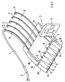
- Figure 1 shows a graphical representation Dental work tool with a device housing 1, on the a plurality of swing arms 2 in a manner which will be explained in more detail later are stored so that they from the drawn rest position can be inclined towards the operating side.
- the swing arms are used to support dental supply lines hose-bound handpieces, of which here in the illustration only one is shown for the sake of simplicity.
- the Handpiece 3 shown here is in one of its storage drawn condition drawn; the associated supply hose 4 is by means of annular holding elements 5, 6 supported on the swing arm so that it is held like a loop will.
- the housing 1 consists of a trough-shaped lower shell 7 ( Figure 2) and an attached cover 8.
- the cover 8 is divided at a parting line designated by 9 in a front part facing the operating side 8a and a rear part 8b. Are in the area of the parting line 9 openings 10 through which the hose ends into the Device housing or to the underside of the device housing are performed according to connections not shown.
- the front cover part 8a contains trough-shaped shelves 11 for the handpieces.
- the trough-shaped shelves are through a wavy contour of the housing in this area formed ( Figure 4), being in the troughs in the area of Overlay of handpieces inlays 12 with increased static friction are provided.
- the front cover part 8a contains the handpiece trays 11 on both sides Grip recesses 13 and is easily removable at the rear part 8b supported.
- the front part can be very easily into an appropriate cleaning or disinfection device With 14 there is an operating and display panel designated.
- the surface of the cover 8 is formed by essentially two intersecting, concave curved surfaces F1 and F2.
- the area F1 includes essentially the outer contour of the housing 8 and is of the smaller and narrower area F2.
- the Section line S of the two surfaces F1 and F2 represents, as it were the parting line 9 is for the two parts 8a and 8b.
- FIG 3 shows a graphical representation of the rear part 8b of the cover 8 partially in section.
- the holding means 18 included a bearing block 19 mounted in the lower shell 7, the one by a tension spring 20 loaded rotary segment 21.
- the support part 23 shown offset is attached, which has a protruding tongue 24 on which the lower end 2a of the swing arm can be snapped on can.
- a correspondingly large opening 25 in the cover 8 ensures that the swing arm mentioned above Can perform pan or tilt movement.
- the push buttons 26 are part of the removable housing part 8a; the one with the push buttons interacting switching mechanism, however, is in the fixed Housing part 8b housed.
- Figure 3 is the arrangement the switching mechanism indicated with item 27.
Landscapes
- Health & Medical Sciences (AREA)
- Life Sciences & Earth Sciences (AREA)
- Animal Behavior & Ethology (AREA)
- General Health & Medical Sciences (AREA)
- Public Health (AREA)
- Veterinary Medicine (AREA)
- Dental Tools And Instruments Or Auxiliary Dental Instruments (AREA)
Abstract
Description
Claims (8)
- Zahnärtztliches Arbeitsgerät mit einem Gehäuse (1) welches muldenförmige Ablagen (11) für schlauchgebundene Handstücke enthält, deren Versorgungsschläuche (4) von peitschenförmig gestalteten Schwingarmen (2) gehalten werden, die an unterhalb der Abdeckung befindlichen Haltemitteln (18) so gehaltert sind, daß sie aus einer Ruhestellung mit schräg aufwärts und von der Bedienseite weg gerichteter Position in eine zur Bedienseite hin gerichtete Arbeitsposition neigbar sind, dadurch gekennzeichnet, daß das Gehäuse (1) eine wannenförmige Unterschale (7) und eine darüber befindliche Abdeckung (8) enthält, daß die Oberfläche der Abdeckung (8) durch im wesentlichen zwei sich schneidende Flächen (F1, F2) gebildet ist, eine im wesentlichen die äußere Kontur des Gehäuses umfassende größere Fläche (F1) und eine diese durchdringende kleinere Fläche (F2), daß die Schnittlinie (S) der beiden Flächen (F1, F2)die kleinere Fläche (F2) unterteilt in einen vorderen, gegenüber der größeren Fläche (F1) abgesenkten und in einen rückwärtigen, gegenüber der größeren Fläche (F1) erhöhten Flächenabschnitt (15, 16), wobei im abgesenkten Flächenabschnitt (15) die muldenförmigen Handstückablagen (11) und im erhöhten Flächenabschnitt (16) die Haltemittel (18) der Schwingarme (2) angeordnet sind.
- Zahnärtztliches Arbeitsgerät nach Anspruch 1, dadurch gekennzeichnet, daß die Schnittlinie (S) gleichsam eine Trennfuge (9) ist, welche das Gehäuse (1), vorzugsweise nur die Abdeckung (8), in einen zumindest die Handstückablagen (11) beinhaltenden vorderen, der Bedienseite zugewandten abnehmbaren Gehäuseteil (8a) und in einen rückwärtigen , demgegenüber festen Gehäuseteil (8b) unterteilt.
- Zahnärtztliches Arbeitsgerät nach Anspruch 1, dadurch gekennzeichnet, daß die beiden Flächen (F1, F2) der Abdeckung (8) konkav gewölbt sind.
- Zahnärtztliches Arbeitsgerät nach Anspruch 1, dadurch gekennzeichnet, daß die Handstückablagen (11) auf der kleineren Fläche (F2) durch eine wellenförmige Kontur des Gehäuseteils (8a)gebildet sind.
- Zahnärtztliches Arbeitsgerät nach Anspruch 4, dadurch gekennzeichnet, daß in den Wellentälern (15) im Bereich der Handstückauflagen Einlagen (12) mit erhöhter Haftreibung vorgesehen sind.
- Zahnärtztliches Arbeitsgerät nach Anspruch 5, dadurch gekennzeichnet, daß die Einlagen (12) in Ausnehmungen der Gehäuseoberfläche eingeclipst sind.
- Zahnärtztliches Arbeitsgerät nach einem der Ansprüche 1 bis 6, dadurch gekennzeichnet, daß das abnehmbare Gehäuseteil (8a) mit voorzugsweise beidseitig der Handstückablagen (11) angeordneten Griffmulden (13) versehen ist.
- Zahnärztliches Arbeitsgerät nach einem der Ansprüche 2 bis 7, dadurch gekennzeichnet, daß im abnehmbaren Gehäuseteil (8a) Auslöseelemente (26) für eine im feststehenden Gehäuseteil (8b) untergebrachte Schaltmechanik (27) vorgesehen sind.
Applications Claiming Priority (2)
| Application Number | Priority Date | Filing Date | Title |
|---|---|---|---|
| DE29613038U | 1996-07-26 | ||
| DE29613038U DE29613038U1 (de) | 1996-07-26 | 1996-07-26 | Zahnärztliches Arbeitsgerät |
Publications (3)
| Publication Number | Publication Date |
|---|---|
| EP0820732A2 true EP0820732A2 (de) | 1998-01-28 |
| EP0820732A3 EP0820732A3 (de) | 1999-03-24 |
| EP0820732B1 EP0820732B1 (de) | 2003-03-26 |
Family
ID=8027071
Family Applications (1)
| Application Number | Title | Priority Date | Filing Date |
|---|---|---|---|
| EP97112550A Expired - Lifetime EP0820732B1 (de) | 1996-07-26 | 1997-07-22 | Zahnärztliches Arbeitsgerät |
Country Status (2)
| Country | Link |
|---|---|
| EP (1) | EP0820732B1 (de) |
| DE (2) | DE29613038U1 (de) |
Cited By (3)
| Publication number | Priority date | Publication date | Assignee | Title |
|---|---|---|---|---|
| DE19916158A1 (de) * | 1999-04-11 | 2000-10-19 | Duerr Dental Gmbh Co Kg | Dentale Behandlungseinrichtung |
| DE10329802B3 (de) * | 2003-07-01 | 2005-03-17 | Sirona Dental Systems Gmbh | Vorrichtung zur Aufnahme dentaler Handinstrumente |
| US11432984B2 (en) * | 2018-04-05 | 2022-09-06 | Kristen Hanlan | Dental tool holder |
Family Cites Families (2)
| Publication number | Priority date | Publication date | Assignee | Title |
|---|---|---|---|---|
| DE3514831A1 (de) * | 1985-04-24 | 1986-11-06 | Siemens AG, 1000 Berlin und 8000 München | Zahnaerztliches geraet mit an versorgungsleitungen gebundenen handstuecken |
| US5334018A (en) * | 1992-12-08 | 1994-08-02 | Mdt Corporation | Dental control unit with removable cover |
-
1996
- 1996-07-26 DE DE29613038U patent/DE29613038U1/de not_active Expired - Lifetime
-
1997
- 1997-07-22 DE DE59709601T patent/DE59709601D1/de not_active Expired - Fee Related
- 1997-07-22 EP EP97112550A patent/EP0820732B1/de not_active Expired - Lifetime
Cited By (4)
| Publication number | Priority date | Publication date | Assignee | Title |
|---|---|---|---|---|
| DE19916158A1 (de) * | 1999-04-11 | 2000-10-19 | Duerr Dental Gmbh Co Kg | Dentale Behandlungseinrichtung |
| DE19916158C2 (de) * | 1999-04-11 | 2001-03-01 | Duerr Dental Gmbh Co Kg | Dentale Behandlungseinrichtung |
| DE10329802B3 (de) * | 2003-07-01 | 2005-03-17 | Sirona Dental Systems Gmbh | Vorrichtung zur Aufnahme dentaler Handinstrumente |
| US11432984B2 (en) * | 2018-04-05 | 2022-09-06 | Kristen Hanlan | Dental tool holder |
Also Published As
| Publication number | Publication date |
|---|---|
| DE59709601D1 (de) | 2003-04-30 |
| EP0820732A3 (de) | 1999-03-24 |
| DE29613038U1 (de) | 1997-11-27 |
| EP0820732B1 (de) | 2003-03-26 |
Similar Documents
| Publication | Publication Date | Title |
|---|---|---|
| DE19628172B4 (de) | Spender für Flüssigkeiten, insbesondere Flüssigseife | |
| DE2426291A1 (de) | Dentalinstrumentauslegeanordnung | |
| EP0278360A2 (de) | Vorrichtung zur Reinigung von medizinischen Handinstrumenten sowie Handgeräten für die Haar- Haut- bzw. Körperpflege | |
| DE1263220B (de) | Zahnarztstuhl | |
| DE102020133299A1 (de) | Fahrzeugarmlehne und Fahrzeugsitz | |
| EP0529132B1 (de) | Zahnärztlicher Instrumentenablagetisch | |
| EP0820732B1 (de) | Zahnärztliches Arbeitsgerät | |
| DE10122129B4 (de) | Waschtisch zum Haarewaschen | |
| DE29706247U1 (de) | Arbeitstisch, insbesondere für Dentallabors | |
| DE19916158C2 (de) | Dentale Behandlungseinrichtung | |
| DE69503834T2 (de) | Müllsammelfahrzeug mit Trittbrettern | |
| DE102008023842A1 (de) | Vorrichtung zur Halterung wenigstens eines medizinischen oder dentalmedizinischen Instruments | |
| DE2704308A1 (de) | Kombinierte sprueh- und saugvorrichtung zur reinigung von polstern und teppichen | |
| EP1131032B1 (de) | Patientenstuhl | |
| DE4428890C1 (de) | Vorrichtung zum Tragen des Monitors und der Tastatur eines Büroinformationssystems | |
| DE3116206C2 (de) | Halter zur Aufnahme eines zahnärztlichen Handstücks | |
| DE69621686T2 (de) | Ergonomischer Handgriff | |
| EP0008415B1 (de) | Zahnärztlicher Patientenstuhl mit schwenkbar gehalterter Rückenlehne | |
| DE8015279U1 (de) | Zahnaerztliche arbeitsvorrichtung fuer ergonomische behandlungsweise | |
| EP1038471B1 (de) | Schreibtisch mit einer Ablagerinne | |
| DE3021603A1 (de) | Zahnaerztliche arbeitsvorrichtung fuer ergonomische behandlungsweise | |
| DE10050014A1 (de) | Kehrschaufel mit einem Abnützungsmindernden Organ | |
| DE2041169A1 (de) | Zahnaerztliches Zusatzgeraet | |
| EP4159330A1 (de) | Reinigungsanlage für ein vorlaufband eines kassentisches | |
| Maier | Cattani, L.," La preghiera quotidiana di Israele"(Book Review) |
Legal Events
| Date | Code | Title | Description |
|---|---|---|---|
| PUAI | Public reference made under article 153(3) epc to a published international application that has entered the european phase |
Free format text: ORIGINAL CODE: 0009012 |
|
| AK | Designated contracting states |
Kind code of ref document: A2 Designated state(s): DE DK FI FR IT |
|
| RAP1 | Party data changed (applicant data changed or rights of an application transferred) |
Owner name: SIRONA DENTAL SYSTEMS GMBH & CO.KG |
|
| PUAL | Search report despatched |
Free format text: ORIGINAL CODE: 0009013 |
|
| AK | Designated contracting states |
Kind code of ref document: A3 Designated state(s): AT BE CH DE DK ES FI FR GB GR IE IT LI LU MC NL PT SE |
|
| RAP1 | Party data changed (applicant data changed or rights of an application transferred) |
Owner name: SIRONA DENTAL SYSTEMS GMBH |
|
| 17P | Request for examination filed |
Effective date: 19990713 |
|
| AKX | Designation fees paid |
Free format text: DE DK FI FR IT |
|
| GRAG | Despatch of communication of intention to grant |
Free format text: ORIGINAL CODE: EPIDOS AGRA |
|
| 17Q | First examination report despatched |
Effective date: 20020515 |
|
| GRAG | Despatch of communication of intention to grant |
Free format text: ORIGINAL CODE: EPIDOS AGRA |
|
| GRAG | Despatch of communication of intention to grant |
Free format text: ORIGINAL CODE: EPIDOS AGRA |
|
| GRAH | Despatch of communication of intention to grant a patent |
Free format text: ORIGINAL CODE: EPIDOS IGRA |
|
| GRAH | Despatch of communication of intention to grant a patent |
Free format text: ORIGINAL CODE: EPIDOS IGRA |
|
| GRAA | (expected) grant |
Free format text: ORIGINAL CODE: 0009210 |
|
| AK | Designated contracting states |
Designated state(s): DE DK FI FR IT |
|
| PG25 | Lapsed in a contracting state [announced via postgrant information from national office to epo] |
Ref country code: IT Free format text: LAPSE BECAUSE OF FAILURE TO SUBMIT A TRANSLATION OF THE DESCRIPTION OR TO PAY THE FEE WITHIN THE PRE;WARNING: LAPSES OF ITALIAN PATENTS WITH EFFECTIVE DATE BEFORE 2007 MAY HAVE OCCURRED AT ANY TIME BEFORE 2007. THE CORRECT EFFECTIVE DATE MAY BE DIFFERENT FROM THE ONE RECORDED.SCRIBED TIME-LIMIT Effective date: 20030326 Ref country code: FR Free format text: LAPSE BECAUSE OF FAILURE TO SUBMIT A TRANSLATION OF THE DESCRIPTION OR TO PAY THE FEE WITHIN THE PRESCRIBED TIME-LIMIT Effective date: 20030326 Ref country code: FI Free format text: LAPSE BECAUSE OF FAILURE TO SUBMIT A TRANSLATION OF THE DESCRIPTION OR TO PAY THE FEE WITHIN THE PRESCRIBED TIME-LIMIT Effective date: 20030326 |
|
| REF | Corresponds to: |
Ref document number: 59709601 Country of ref document: DE Date of ref document: 20030430 Kind code of ref document: P |
|
| PG25 | Lapsed in a contracting state [announced via postgrant information from national office to epo] |
Ref country code: DK Free format text: LAPSE BECAUSE OF FAILURE TO SUBMIT A TRANSLATION OF THE DESCRIPTION OR TO PAY THE FEE WITHIN THE PRESCRIBED TIME-LIMIT Effective date: 20030626 |
|
| PLBE | No opposition filed within time limit |
Free format text: ORIGINAL CODE: 0009261 |
|
| STAA | Information on the status of an ep patent application or granted ep patent |
Free format text: STATUS: NO OPPOSITION FILED WITHIN TIME LIMIT |
|
| EN | Fr: translation not filed | ||
| 26N | No opposition filed |
Effective date: 20031230 |
|
| PGFP | Annual fee paid to national office [announced via postgrant information from national office to epo] |
Ref country code: DE Payment date: 20080729 Year of fee payment: 12 |
|
| PG25 | Lapsed in a contracting state [announced via postgrant information from national office to epo] |
Ref country code: DE Free format text: LAPSE BECAUSE OF NON-PAYMENT OF DUE FEES Effective date: 20100202 |