EP0820734A1 - Winkelförmiges oder gerades Handstück mit einer lösbaren Spannvorrichtung für ein rotierendes Werkzeug, insbesondere für medizinische oder dentale Zwecke - Google Patents
Winkelförmiges oder gerades Handstück mit einer lösbaren Spannvorrichtung für ein rotierendes Werkzeug, insbesondere für medizinische oder dentale Zwecke Download PDFInfo
- Publication number
- EP0820734A1 EP0820734A1 EP97112559A EP97112559A EP0820734A1 EP 0820734 A1 EP0820734 A1 EP 0820734A1 EP 97112559 A EP97112559 A EP 97112559A EP 97112559 A EP97112559 A EP 97112559A EP 0820734 A1 EP0820734 A1 EP 0820734A1
- Authority
- EP
- European Patent Office
- Prior art keywords
- coupling
- slide
- clutch
- drive sleeve
- tool
- Prior art date
- Legal status (The legal status is an assumption and is not a legal conclusion. Google has not performed a legal analysis and makes no representation as to the accuracy of the status listed.)
- Granted
Links
- 230000008878 coupling Effects 0.000 claims abstract description 67
- 238000010168 coupling process Methods 0.000 claims abstract description 67
- 238000005859 coupling reaction Methods 0.000 claims abstract description 67
- 229910010293 ceramic material Inorganic materials 0.000 claims description 20
- 238000002347 injection Methods 0.000 claims description 5
- 239000007924 injection Substances 0.000 claims description 5
- 238000000465 moulding Methods 0.000 claims description 2
- 238000000034 method Methods 0.000 claims 1
- 239000000463 material Substances 0.000 abstract description 8
- 239000000919 ceramic Substances 0.000 abstract description 6
- 238000004519 manufacturing process Methods 0.000 description 9
- 230000006835 compression Effects 0.000 description 5
- 238000007906 compression Methods 0.000 description 5
- 229910000831 Steel Inorganic materials 0.000 description 3
- 238000004040 coloring Methods 0.000 description 3
- 238000003780 insertion Methods 0.000 description 3
- 230000037431 insertion Effects 0.000 description 3
- 239000002184 metal Substances 0.000 description 3
- 239000010959 steel Substances 0.000 description 3
- XLYOFNOQVPJJNP-UHFFFAOYSA-N water Substances O XLYOFNOQVPJJNP-UHFFFAOYSA-N 0.000 description 3
- 239000003086 colorant Substances 0.000 description 2
- 238000013461 design Methods 0.000 description 2
- 238000002474 experimental method Methods 0.000 description 2
- 238000012805 post-processing Methods 0.000 description 2
- 238000005299 abrasion Methods 0.000 description 1
- 230000001154 acute effect Effects 0.000 description 1
- 238000013459 approach Methods 0.000 description 1
- 230000008602 contraction Effects 0.000 description 1
- 238000006073 displacement reaction Methods 0.000 description 1
- 230000009969 flowable effect Effects 0.000 description 1
- 230000020169 heat generation Effects 0.000 description 1
- 238000005461 lubrication Methods 0.000 description 1
- 238000003754 machining Methods 0.000 description 1
- 238000012423 maintenance Methods 0.000 description 1
- 239000003550 marker Substances 0.000 description 1
- 239000000203 mixture Substances 0.000 description 1
- 238000005192 partition Methods 0.000 description 1
- 230000002093 peripheral effect Effects 0.000 description 1
- 238000003825 pressing Methods 0.000 description 1
- 238000007789 sealing Methods 0.000 description 1
- 239000007921 spray Substances 0.000 description 1
- 238000005507 spraying Methods 0.000 description 1
- 230000006641 stabilisation Effects 0.000 description 1
- 238000011105 stabilization Methods 0.000 description 1
- 239000007858 starting material Substances 0.000 description 1
- 238000013519 translation Methods 0.000 description 1
Images


Classifications
-
- A—HUMAN NECESSITIES
- A61—MEDICAL OR VETERINARY SCIENCE; HYGIENE
- A61C—DENTISTRY; APPARATUS OR METHODS FOR ORAL OR DENTAL HYGIENE
- A61C1/00—Dental machines for boring or cutting ; General features of dental machines or apparatus, e.g. hand-piece design
- A61C1/08—Machine parts specially adapted for dentistry
- A61C1/14—Tool-holders, i.e. operating tool holders, e.g. burr holders
- A61C1/142—Operating tool blocking means
- A61C1/144—Operating tool blocking means constricting the operating tool, e.g. chuck
-
- Y—GENERAL TAGGING OF NEW TECHNOLOGICAL DEVELOPMENTS; GENERAL TAGGING OF CROSS-SECTIONAL TECHNOLOGIES SPANNING OVER SEVERAL SECTIONS OF THE IPC; TECHNICAL SUBJECTS COVERED BY FORMER USPC CROSS-REFERENCE ART COLLECTIONS [XRACs] AND DIGESTS
- Y10—TECHNICAL SUBJECTS COVERED BY FORMER USPC
- Y10S—TECHNICAL SUBJECTS COVERED BY FORMER USPC CROSS-REFERENCE ART COLLECTIONS [XRACs] AND DIGESTS
- Y10S415/00—Rotary kinetic fluid motors or pumps
- Y10S415/904—Tool drive turbine, e.g. dental drill
Definitions
- the invention relates to a handpiece according to the preamble of claim 1 or 2.
- the releasable coupling has an embodiment for axially connecting the tool shank with the drive sleeve a slide arranged on one side of the shaft (FIG. 1) or two slides arranged on both sides of the shaft (FIG. 2).
- the slide in a radial guide groove of the drive sleeve radially between a radially inward clutch position and a radial outward release position slidable and by a spring force in the Coupling position acted upon elastically.
- Coupling slide is a component that works with the The drive sleeve rotates, while the pressure member does not normally rotate during this rotation participates.
- a head housing of a dental handpiece with a similar detachable coupling for the axial connection of the shaft with the drive sleeve is in DE-GM 89 13 626 described.
- the invention has for its object a handpiece or a clutch slide to be designed in such a way that a lighter one is guaranteed while ensuring low wear automatic loosening of the coupling when inserting the tool shank into the Drive sleeve is possible.
- the clutch slide partially made of a ceramic material, at least partially coated or can consist partially or completely of the ceramic material.
- the lower specific weight of the invention Clutch slide to a lower moment of inertia and to a lower one Vibrations in functional operation. This also results in a lower running noise in the Functional operation.
- Another advantage is that less because of less wear Wear residues (abrasion) arise in the housing, which is also desirable.
- the invention is advantageous not only in those handpieces in which the Coupling slide is a component rotating with the drive sleeve, but also at such handpieces in which the clutch slide in a guide of the housing is slidably mounted and therefore does not participate in the rotation of the drive sleeve and thus during the rotation with the shank of the tool in constant sliding engagement stands.
- the pressure member consists of ceramic material or accordingly is coated.
- the invention also relates to a clutch slide, and / or a pressure member each as Individual part for a handpiece which is designed according to the invention.
- the actuating device can have a pressure member which into the housing of the handpiece, preferably coaxially and insertable against a spring and pushes the clutch slider into its uncoupling position when inserted.
- the pressure member can be formed by means of an oblique or conical section Actuating surface against a correspondingly sloping or cone-shaped Hit the actuating surface on the clutch slide.
- the oblique or cone-shaped Actuating surface can protrude from the clutch slide to the pressure element Bridge can be arranged.
- the return spring for the clutch slide can be ring-shaped or C-shaped surround, preferably together with the clutch slide opposite section of the drive sleeve, the spring the clutch slide and can surround the drive sleeve in a ring. It is advantageous if the Coupling slide in its preferably cylindrical section-shaped lateral surface Has circumferential groove for receiving the spring, preferably the circumferential groove itself can continue in the outer surface of the drive sleeve as a circumferential groove.
- the spring one C-shaped shape preferably in the sense of a clasp, and the distance of the Spring ends is adapted approximately to the distance between the groove sections.
- the coupling part can be easily and inexpensively in one Manufacture molding tool, the flowable starting material of the clutch slide is conveyed into the mold by means of a feed line, with the Mouth of the feed line forms a so-called injection area can be inaccurate, e.g. due to a closure of the mold cavity after the Insertion of the material or due to a break off of the hardened Excess material in the injection area.
- the clutch slider has a preferably elongate injection area, which in particular follows is arranged offset region of the lateral surface, preferably next to the Circumferential groove, especially in the area of an axially projecting web.
- the pressure member has a mushroom-shaped shape with one in the housing of the handpiece extending actuating approach.
- the pressure member on its visible surface Has marking that indicates a special function of the handpiece.
- the Marking is preferably colored or formed by a color, in particular has the color red, blue, green and / or yellow.
- the color of the marker can only be on a sub-area, e.g. a mark, the visible surface of the Pressure member or be arranged on the entire surface. It is in the further advantageous, the marking by coloring the ceramic material on the Form surface or the ceramic material overall with the associated color to colorize.
- the main parts of a present handpiece are a grip sleeve 1 with a Head housing 2 at its front end, a drive shaft section 3, which in the Grip sleeve 1 is rotatably mounted, a drive sleeve 4, which by means of pivot bearings 5
- the axis of rotation 6 is rotatably mounted in the head housing 2, the axis of rotation 6 being different preferably extends at right angles to the longitudinal central axis 7 of the grip sleeve 1, one Drive connection between the drive shaft section 3 and the drive sleeve 4, here in the form of an angular gear 8 with corresponding pinions, a first clutch 9 for releasable rotary driving connection of an externally insertable into the drive sleeve 4 Shank 11 of a rotary tool 12, a second clutch 13 for releasable axial Connection of the shaft 11 to the drive sleeve 4 and an actuating device 14 for releasing the second coupling 13 in order to remove the tool 12 from the Hand
- the grip sleeve 1 can by a connector 15 with a coupling pin 15a and a coupling recess 15b receiving it with a connector 17 flexible supply line 18 can be connected, the other end of which is not shown supply device for supplying the handpiece with necessary Media such as electrical drive energy, blown air, water and / or spray, connected is.
- So-called media lines 16, which run lengthwise through the supply line 18, are used for this purpose and the connector 15 can extend, as is known per se.
- the Media lines for water and / or air and light end in or near the Head housing 2, with its outlet openings on the top of the tool 12 located treatment center are directed.
- the present handpiece can also be a so-called turbine, in which a compressed air-carrying drive line up to one in the sense described above Head housing 2 arranged drive turbine extends.
- a so-called turbine in which a compressed air-carrying drive line up to one in the sense described above Head housing 2 arranged drive turbine extends.
- the plug connection 15 is also advantageous to use as a plug / turn connection.
- the passage of the media lines through the Plug / turn connection so that the passage of the media in every turning position is guaranteed.
- the cylindrical dividing line between the coupling pin 15a and the coupling recess 15b approximately radially setting channels formed, each in the area of the dividing groove with an annular groove Stand connection and are sealed by axially spaced sealing rings.
- An one unintentional loosening of the connector 15 preventing device is by Spring element 20a and a recess 20b receiving it in the area of Partition joint formed, as is known per se.
- the first clutch 9 is connected by an inner projection 21 in the drive sleeve 4 a secantial coupling surface 22 formed on the also secantial Coupling surface 23 of the shaft 11 abuts with little movement, the Coupling surface 22 through a recess or flattening of the end Shaft 11 is formed.
- the inner projection 21 is formed by a circular section-shaped coupling part, which is used as a fitting in a secant groove N, which has a corresponding width b and Has depth t.
- the groove N opens at the Shell surface of the drive sleeve, wherein it is arranged at such a height that they at least partially from the inner ring of the associated roller bearing Pivot bearing 5 is covered.
- the fitting piece P is form-fitting in the groove N held.
- the second coupling 13 for axially effective connection of the shaft 11 with the Drive sleeve 4 is by a clutch slide 24, which is in a radial Guide slot of the drive sleeve 4 radially displaceable with little movement is mounted, and has a coupling nose 25 at its radially inner end, and a the latter receiving coupling recess 26 is formed in the shaft 11.
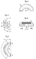
- the clutch slide 24 shown as an individual part in FIGS. 3 to 5 is in plan view seen semi-ring-shaped or crescent-shaped, his Outer lateral surface is curved in the shape of a cylindrical section.
- the clutch slide 24 consists of two integral parts, namely one semi-annular slide section 24a with mutually parallel lower and upper surfaces 28,29, with which he with little movement in a radial guide slot 31 in the drive sleeve 4 sits and is radially displaceable therein.
- the radial guide thus formed is designated 30.
- the coupling lug 25 is formed on the radial inside of the sliding section 24a, wherein it by a circumferential arcuate section or formed in a somewhat larger curvature 35, the underside has a run-on slope in the form of a conical surface 36 in the form of a conical section.
- the tip of the nose here the ring-section-shaped tip of the nose preferably blunted by a cylindrical section-shaped ring section surface.
- W1 of the conical surface 36 closes with the vertical an angle W1 of approx. 33 °.
- the shaft 11 of the tool 12 preferably has Peripheral edge of its free end a chamfer corresponding angle or Rounding up.
- the clutch slide 24 is between a clutch position shown in Fig. 2, in which is limited inward movement by a stop A and in which the Coupling nose 25 protrudes into the hollow cylindrical plug hole 4a of the drive sleeve 4 and a decoupling position or release position shifted outwards displaceable, in which the coupling lug 25 does not protrude into the plug hole 4a. It is the arrangement made so that in the coupling position in the plug hole 4a inserted shaft 11 meets the conical surface 36 and by this wedge drive Clutch slide 24 is moved into its release position.
- annular spring or clip-shaped spring 37 made of a cross-section e.g. round Spring wire is formed, which for its axial securing in a circumferential groove 38 in the Shell surface 28a sits.
- the drive sleeve preferably also has in the same transverse plane 4 such a circumferential groove 38a, in which the annular spring 37 is seated.
- the spring 37 will elastically opened when the clutch slide 24 is moved into its release position, which enables their clasp-like or C-shape. Thanks to the elastic contraction the spring 34, the coupling piece 24 is automatically in its coupling position postponed. In this position, the spring 37 still exerts a bias on the Coupling piece 24.
- Unlocking hole 4a is - seen in plan view - the concave curvature of the Nose bow 35 larger than a corresponding cylindrical section-shaped curvature or formed with a corresponding enlargement outlet flanks, so that also the nasal arch ends in the release position are outside the plug hole 4a.
- the bottom 31a of the guide slot 31 is diametrical or, in contrast, somewhat radially offset to the outside.
- the stop A limiting the insertion movement of the coupling slide 24a can between the radial inner boundary surfaces 39 of the clutch slide 24 and the Bottom 31a of the guide slot 31 or between the step surface 34 and the Shell surface of the drive sleeve 4 may be formed.
- the clutch slide is in the outer surface 28a 24 two groove sections 38b, 38c are provided, one in the side view according to FIG Have distance e from each other, whereby a web 40 is formed. A corresponding one Taking into account a play of movement, distance e also have the ends of annular spring 37, the assembled spring 37 with its free ends located on both sides of this web and thereby against rotation in the circumferential direction is secured.
- the actuator 14 is provided, which on the Arranged from the tool 12 side of the head housing 2 or from this Page is accessible.
- the actuating device 14 a pressure member 46 which is axially in a guide 47 between an inward shifted functional position and an outwardly shifted standby position is manually displaceable.
- the pressure member 46 is a round cap of the Head housing 2 through a preferably round opening 48 of the head housing 2 is accessible or penetrates the opening to the outside and in particular the head housing 2 protrudes outwards and the opening 48 with a guarantor Movement play closes.
- the pressure member 46 On its inside, the pressure member 46 has a cylindrical or preferably hollow cylindrical actuating projection 49, one on its free outer edge Has outer conical surface 51 with an angle corresponding to the angle W.
- the pressure member 46 is biased into its ready position by a spring 52, in which is limited its outward movement by a stop 53 which at the present embodiment is formed by an inner annular shoulder 54 on which one outer ring shoulder 55 on the pressure member 46 under the pressure of preferably as Compression spring trained spring 52 abuts.
- the inner end of the compression spring 52 is supported on a shoulder surface of the head housing 2.
- this is Pressure member 46 in an annular insert, in particular screw part 56, arranged with a sleeve section 57 with an external thread in a corresponding Internal thread of the head housing 2 is screwed.
- the insert preferably has a flange 58; which rests on the top of the head housing 2.
- the coaxial guide 47 for the pressure member 46 can be realized in several ways be.
- the guide 47 can pass through the outer lateral surface 47a of the pressure element 46 and the inner lateral surface 47b of the housing 2 or here of the screw part 56 can be formed.
- a coaxial guide 47a can additionally or possibly only between the cylindrical inner surface 49a of the actuating projection 49 and the cylindrical outer circumferential surface 50a of the facing end region 50 of the drive sleeve 4 be provided. No rotation takes place in the guide 47, since the pressure member 46 would be rotatable, but does not rotate in normal functional operation.
- guidance takes place in the guide 47a when the pressure member 46 is inserted and the drive sleeve 4 rotates, e.g.
- This guide 47a can thus in the inserted position of the pressure member 46 a small braking force on the expiring Exercise drive sleeve 4 and that in the context of a guide resistance that turns out to be Braking force affects the drive sleeve 4.
- the inner abutment for the compression spring 52 is formed by a spring ring 59 which in a corresponding inner ring groove 61 of the sleeve portion 57 in its inner end region is inserted.
- the spring ring 59 forms in the used position of the insert or screw 56 an upper limit for the Outer ring of a roller bearing 62 forming the associated pivot bearing 6.
- the spring ring 59, the compression spring 52 and the pressure member 46 thus form one pre-assembled unit, which can be easily inserted or screwed in is mountable.
- the upper area is not shown Attack element, e.g. opposite holes for a screwing tool intended.
- the pressure member 46 can with the spring ring 59 removed from below into the Insert or screw part 56 are inserted and then the spring ring 59th used.
- the outer conical surface 51 has one Distance from the corresponding inner conical surface 36, which is preferably is low and e.g. can be about 1mm.
- the segmented e.g. can be formed as a secant groove, or annular.
- the clutch slide 24 is a component, that rotates with the drive sleeve 4. Therefore, when the actuator 14 for Disengage the clutch 13 during the rotation or during the phase-out of the Drive sleeve 4 is actuated, in particular occur between the conical surfaces 36, 51, but also in the guide 30 of the clutch slide 24 and / or in the guide 47 of the Pressure member 46 on frictional forces; which lead to "eating" at the contact or Can guide surfaces, which damage the functional parts. To do this to avoid and also to the clutch slide 24 and / or pressure member 46th and to give the components interacting with it a longer service life the clutch slide 24 on at least one of its friction surfaces, e.g.
- the coupling slide When the coupling slide is manufactured entirely from ceramic material, it can be produced as a molded part or as a molded part or as a cast part or as a pressed part.
- the coupling slide can be produced directly into its final form in the aforementioned manufacturing measures be, which leads to a significant simplification of manufacture and the Manufacturing costs are reduced.
- a polycrystalline has proven to be an advantageous ceramic material in experiments Ceramic material proven, especially with a high degree of purity of e.g. 99% and more.
- the clutch slide 24 is manufactured as a molded part, it is advantageous to use the one shown in FIG cross-hatching shows injection area B on the lateral surface 28 to be arranged, in particular in the area of the web 32 The least disturbing surface inaccuracy caused by spraying. It can the lateral surface in the area of the web 32 with respect to the remaining lateral surface 28 be slightly radially inward, as shown in FIG. 5.
- a non-positive clutch 101 is in the Sense of a clamping coupling between the drive sleeve 4 and the shaft 12 of the Tool provided.
- This clutch 101 is both in the axial direction and in Effective circumferential direction.
- the drive sleeve consists of an outer bearing sleeve 4a and a clamping sleeve 4b firmly inserted therein, the inner or the tool 12 opposite end area is tapered as the clamping area outside.
- This clutch 101 is known. It becomes diametrically opposed to each other Opposing adapter sleeve segments 4c, 4d formed by an axial slot 102 are separated from each other, the end of the shank facing away from the tool 12 11 runs out and towards the tool head in the clamping area designated S and also extends into the holding area of the drive sleeve 4 designated by H and ends therein.
- the internal cross-sectional dimension is essentially the Hollow cylindrical clamping sleeve 4b dimensioned somewhat smaller than in the holding area H.
- a pressure slide 105 above the clamping sleeve 4b in the bearing sleeve 4a axially displaceably mounted on the end face facing the clamping sleeve 4b has two pressure wedges 107 diametrically opposite each other, which in the slot 102nd border as shown in Fig. 7.
- the pressure slide 105 has a lower enlarged Longitudinal section 105a, which is mounted with play in the bearing sleeve 4a and has an upper longitudinal portion 105b which is tapered in diameter.
- the annular cavity of the axially movable pressure slide 105 is a movement of the Drive sleeve 4 limiting stop member 106 for setting a pre-setting assigned to the clamping segments 4c, 4d.
- the stop member is by an in formed the upper end of the bearing sleeve 4a screwed adjusting ring.
- a pressure member 46 is coaxial in a guide 47 slidably mounted on the upper end of the housing 2, which between its in Fig. 7th standby position shown and an inwardly shifted operating position manually insertable and back into its ready position by the compression spring 37 is resettable.
- the arrangement and function of this pressure member 46 corresponds to 2, however, the actuating projection 49 also presses a radial end face 51a against the upper radial end face 111 of the pressure slide 105 when the pressure member 46 forming the housing cover is inserted. The latter leads to an opening of the clutch 101 by the pressure wedges 107 the clamping segments 4c, 4d spread and thereby the shaft 11 is free.
- the pressure member 46 is also in the region of its guide surfaces 47a and / or in the area of its pressure surface 51a with a coated ceramic material. It can also be ceramic in these areas Material consist or preferably consist entirely of ceramic material. As a result, the advantages already described are also in this embodiment reached.
- Drive sleeve 4 is mounted with the associated bearing 5 in the screw part 56 and one per se Known turbine drive with a turbine wheel arranged on the drive sleeve 4 112 is provided.
- the pressure member 46 can be easily and inexpensive to produce as a molded part or as a molded part or as a cast part or as a pressed part. There is no need for post-processing after its manufacture, and it can be done with the aforementioned manufacturing measures are made directly to its final shape.
- the desired color can be in Mix in the ceramic material in a simple and cost-effective manner both when the color is mixed into the entire material of the pressure member 46 as well as if only a small spot 113, e.g. a small circular area with the color is colored.
- a small spot 113 e.g. a small circular area with the color is colored.
- the colors Red, blue, green or yellow can be used.
- the coloring of the material leads to the advantage that the color is not in one layer is present, which can flake off or wear off, but due to the coloring is colored through and is insensitive to damage or wear.
Landscapes
- Health & Medical Sciences (AREA)
- Oral & Maxillofacial Surgery (AREA)
- Dentistry (AREA)
- Epidemiology (AREA)
- Life Sciences & Earth Sciences (AREA)
- Animal Behavior & Ethology (AREA)
- General Health & Medical Sciences (AREA)
- Public Health (AREA)
- Veterinary Medicine (AREA)
- Dental Tools And Instruments Or Auxiliary Dental Instruments (AREA)
- Mechanical Operated Clutches (AREA)
Abstract
Description
- Fig. 1
- ein erfindungsgemaßes Handstück in der Seitenansicht;
- Fig. 2
- den Kopf des Handstücks im vertikalen Schnitt;
- Fig. 3
- einen Kupplungsschieber des Handstücks im vertikalen Schnitt;
- Fig. 4
- den Kupplungsschieber in der Seitenansicht von links;
- Fig. 5
- den Kupplungsschieber in der Draufsicht;
- Fig. 6
- den Kupplungsschieber in der Unteransicht;
- Fig. 7
- den Kopf eines erfindungsgemaßen Handstücks in weiter abgewandelter Ausgestaltung im vertikalen Schnitt.
Claims (10)
- Winkelförmiges oder gerades Handstück mit einer lösbaren Haltevorrichtung für ein Werkzeug (12), insbesondere für medizinische oder dentale Zwecke, mitdadurch gekennzeichnet,einem Gehäuse (2),einer darin gelagerten Antriebshülse (4), in die ein Werkzeug (12) mit seinem Schaft (11) einsetzbar ist, und die durch einen Antrieb um eine Drehachse (6) drehbar im Gehäuse (2) gelagert ist,einer lösbaren Kupplung (9) zur Drehmitnahmeverbindung des Schaftes (11) in der Antriebshülse (4), undeiner lösbaren Kupplung (13) zur axialen Verbindung des Schaftes (11) mit der Antriebshülse (4),wobei die letztere Kupplung (13) durch eine Kupplungsausnehmung im Schaft (11) und einen Kupplungsschieber (24) gebildet ist,der zwischen einer in die Kupplungsausnehmung (26) einfassenden Kupplungsstellung und einer den Schaft (11) freigebenden Entkupplungsstellung in einer Führung quer zur Drehachse (6) der Antriebshülse (4) verschiebbar ist, unddurch die Kraft einer Feder (37) in seine Kupplungsstellung beaufschlagt ist,und wobei vorzugsweise eine Betätigungsvorrichtung (14; 72) zum Verschieben des Kupplungsschiebers (24) in seine Entkupplungsstellung vorgesehen ist,
daß der Kupplungsschieber (24)oder daß der Kupplungsschieber (24) insgesamt aus keramischem Material besteht (Fig. 1 bis 10).im Bereich seiner Führungsflächen (28, 29)und/oder im Bereich seiner Kontaktflächen (36) mit der Betätigungsvorrichtung (14)und/oder im Bereich seiner Kontaktflächen mit dem Schaft (11)mit einem keramischen Material beschichtet istoder aus dem keramischen Material besteht, - Winkelförmiges Handstück mit einer lösbaren Haltevorrichtung für ein Werkzeug (12), insbesondere für medizinische oder dentale Zwecke, mitdadurch gekennzeichnet,einem Gehäuse (2),einer darin gelagerten Antriebshülse (4), in die ein Werkzeug (12) mit seinem Schalt (11) einsetzbar ist, und die durch einen Antrieb um eine Drehachse (6) drehbar im Gehäuse (2) gelagert ist,und einer lösbaren Kupplung (101) zur Verbindung des Schaftes (11) mit der Antriebshülse (4),wobei die Kupplung (101) durch eine Feder in ihre Kupplungsstellung beaufschlagt ist,wobei eine Betätigungsvorrichtung (14) zum Betätigen der Kupplung (101) insbesondere in ihre Entkupplungsstellung vorgesehen ist,wobei die Betätigungsvorrichtung (14) ein Druckglied (46) aufweist, das im dem Werkzeug (12) abgewandten Bereich des Gehäuses (2) an dessen Außenseite angeordnet ist,in einer axialen Führung (47) zwischen einer äußeren Freigabestellung und einer inneren Betätigungsstellung verschiebbar geführt ist,und durch eine Feder (37) in seine Freigabestellung beaufschlagt ist,oder winkelförmiges Handstück nach Anspruch 1
daß das Druckstück (46)im Bereich seiner Führungsfläche (47a)und/oder im Bereich seiner Kontaktfläche (51a) mit der Kupplung (101) oder einem Funktionsteil (Druckschieber 105) derselben,mit einem keramischen Material beschichtet ist,oder aus keramischem Material besteht,oder daß das Druckglied (46) insgesamt aus keramischem Material besteht (Fig. 7). - Handstück nach Anspruch 1 oder 2,
dadurch gekennzeichnet,
daß der Kupplungsschieber (24) und/oder das Druckglied (46) einstückig ausgebildet ist. - Handstück nach einem der vorherigen Ansprüche,
dadurch gekennzeichnet,
daß der Kupplungsschieber (24) und/oder das Druckglied (46) jeweils ein Formteil oder ein Spritzteil oder ein Gießteil oder ein Preßteil ist. - Handstück nach Anspruch 4,
dadurch gekennzeichnet,
daß der Kupplungsschieber (24) und/oder das Druckstück (46) jeweils durch seinen Formvorgang ohne Nacharbeit in seine Endform gefertigt ist. - Handstück nach einem der vorherigen Ansprüche,
dadurch gekennzeichnet,
daß der Kupplungsschieber (24) zueinander parallele Unter- und Oberflächen (28, 29) aufweist. - Handstück nach einem der vorherigen Ansprüche,
dadurch gekennzeichnet,
daß der Kupplungsschieber (24) bezüglich der Drehachse (6) der Antriebshülse (4) einseitig angeordnet ist. - Handstück nach einem der vorherigen Ansprüche,
dadurch gekennzeichnet,
daß der Kupplungsschieber (24) - längs der Drehachse (6) gesehen - eine halbringförmige Form aufweist. - Handstück nach einem der vorherigen Ansprüche,
dadurch gekennzeichnet,
daß die Kupplungsnase (25) einen gerundeten oder schrägen Nasenrücken (36) aufweist und die Kupplungsbewegung des Kupplungsschiebers (24) durch einen Anschlag (A) in einer solchen Stellung des Kupplungsschiebers (24) begrenzt ist, daß der Schaft (11) des Werkzeugs (12) beim Einstecken in die Antriebshülse (4) gegen den Kupplungsnasenrücken (36) stößt und den Kupplungsschieber (24) in seine Entkupplungsstellung verdrängt. - Handstück nach einem der vorherigen Ansprüche,
dadurch gekennzeichnet,
daß die Betätigungsvorrichtung (14) von der dem Werkzeug (12) abgewandten Seite des Gehäuses (2) her manuell zugänglich ist.
Applications Claiming Priority (2)
| Application Number | Priority Date | Filing Date | Title |
|---|---|---|---|
| DE19629902A DE19629902A1 (de) | 1996-07-24 | 1996-07-24 | Winkelförmiges oder gerades Handstück mit einer lösbaren Spannvorrichtung für ein rotierendes Werkzeug, insbesondere für medizinische oder dentale Zwecke |
| DE19629902 | 1996-07-24 |
Publications (2)
| Publication Number | Publication Date |
|---|---|
| EP0820734A1 true EP0820734A1 (de) | 1998-01-28 |
| EP0820734B1 EP0820734B1 (de) | 2004-10-13 |
Family
ID=7800725
Family Applications (1)
| Application Number | Title | Priority Date | Filing Date |
|---|---|---|---|
| EP97112559A Expired - Lifetime EP0820734B1 (de) | 1996-07-24 | 1997-07-22 | Winkelförmiges oder gerades Handstück mit einer lösbaren Spannvorrichtung für ein rotierendes Werkzeug, insbesondere für medizinische oder dentale Zwecke |
Country Status (5)
| Country | Link |
|---|---|
| US (1) | US5836766A (de) |
| EP (1) | EP0820734B1 (de) |
| JP (1) | JP3948538B2 (de) |
| AT (1) | ATE279160T1 (de) |
| DE (2) | DE19629902A1 (de) |
Cited By (4)
| Publication number | Priority date | Publication date | Assignee | Title |
|---|---|---|---|---|
| EP0958791A2 (de) | 1998-05-20 | 1999-11-24 | Dentalwerk Bürmoos Gesellschaft M.B.H. | Lösbare Spannvorrichtung für ein rotierendes medizinisches oder dentales Werkzeug |
| EP1378207A1 (de) * | 2002-07-02 | 2004-01-07 | Kaltenbach & Voigt GmbH & Co. KG | Medizinisches oder dentalmedizinisches Handstück mit einer Drucktaste zum Lösen eines Werkzeugs |
| WO2010128131A3 (de) * | 2009-05-07 | 2011-01-06 | W & H Dentalwerk Bürmoos GmbH | Medizinisches handstück |
| US8870570B2 (en) | 2009-03-26 | 2014-10-28 | W&H Dentalwerk Bürmoos GmbH | Chucking device for a medical or dental handpiece |
Families Citing this family (17)
| Publication number | Priority date | Publication date | Assignee | Title |
|---|---|---|---|---|
| JP4942866B2 (ja) * | 2000-08-29 | 2012-05-30 | マニー株式会社 | 歯科用ハンドピース |
| DE10101083C2 (de) * | 2001-01-11 | 2003-02-27 | Axel Kirsch | Bohrvorrichtung zum Bohren in Knochengewebe |
| GB2382048A (en) | 2001-11-20 | 2003-05-21 | Black & Decker Inc | Pivoting electrical connection for a power tool |
| GB2382044A (en) | 2001-11-20 | 2003-05-21 | Black & Decker Inc | A power tool having a handle and a pivotal tool body |
| WO2003083266A1 (en) * | 2002-03-28 | 2003-10-09 | Dentsply International Inc. | Method for balancing the rotating turbine element of a dental handpiece |
| US7137633B1 (en) * | 2004-06-04 | 2006-11-21 | John W Dieleman | Wrench-free manual chuck turbine |
| FR2873566B1 (fr) * | 2004-07-27 | 2007-04-06 | Micro Mega Int Mfg Sa | Dispositif de tenue d'un instrument dentaire |
| EP1728483A1 (de) | 2005-05-30 | 2006-12-06 | Kaltenbach & Voigt GmbH | Handstück mit Beschichtung für bewegte oder bewegbare Teile |
| FR2915084B1 (fr) * | 2007-04-17 | 2009-05-29 | Micro Mega Int Mfg Sa | Dispositif de retention axiale d'une queue d'instrument dentaire comportant un axe traverse par au moins une goupille de blocage. |
| DE102009054746A1 (de) | 2009-02-02 | 2010-08-12 | Kaltenbach & Voigt Gmbh | Zahnärztliches Rotationswerkzeug und zahnärztliches Behandlungsinstrument |
| DE102010037791B4 (de) | 2010-09-27 | 2024-05-08 | Minebea Mitsumi Inc. | Spanneinrichtung für ein Dentalwerkzeug in einem Dentalturbinenhandstück |
| DE102012023437B4 (de) * | 2012-11-30 | 2025-09-11 | Minebea Mitsumi Inc. | Rundlaufoptimiertes Werkzeugspannsystem für Dentalwinkelhandstücke und Dentalturbinen |
| JP5856945B2 (ja) * | 2012-12-10 | 2016-02-10 | 株式会社モリタ製作所 | 工具チャック装置 |
| EP3431034B1 (de) * | 2017-07-17 | 2020-02-26 | Bien-Air Holding SA | Unterelement für zahnärztliches oder chirurgisches handstück, zahnärztliches oder chirurgisches handstück und entsprechendes montageverfahren |
| JPWO2022196783A1 (de) * | 2021-03-18 | 2022-09-22 | ||
| US12433728B2 (en) * | 2021-12-13 | 2025-10-07 | Colt Harrison Canepa | Dental handpiece that has flush capability |
| AU2022436263B2 (en) * | 2022-01-26 | 2025-09-25 | Kazuyoshi Suzuki | Air turbine, dental handpiece, and boost adapter |
Citations (4)
| Publication number | Priority date | Publication date | Assignee | Title |
|---|---|---|---|---|
| EP0245692A2 (de) * | 1986-05-13 | 1987-11-19 | MOSIMANN, David | Bedienungsvorrichtung für Befestigungsmittel eines Werkzeuges in einem Rotor |
| US4966552A (en) * | 1989-05-08 | 1990-10-30 | Den-Tal-Ez, Inc. | Sterilizable non-lubricated rotary instrument for dental and medical use |
| US5022857A (en) * | 1988-12-19 | 1991-06-11 | Matsutani Seisakusho Co., Ltd. | Dental burr and dental handpiece |
| US5312252A (en) * | 1993-06-10 | 1994-05-17 | Abbott Research Corporation | Turbine for a dental handpiece |
Family Cites Families (3)
| Publication number | Priority date | Publication date | Assignee | Title |
|---|---|---|---|---|
| FR2555041A1 (fr) * | 1983-11-23 | 1985-05-24 | Micro Mega Sa | Poussoir |
| ATE61723T1 (de) * | 1986-12-22 | 1991-04-15 | Siemens Ag | Spannvorrichtung fuer insbesondere zahnaerztliche werkzeuge. |
| DE8913626U1 (de) * | 1989-11-17 | 1991-03-21 | Siemens AG, 8000 München | Spannvorrichtung für ein in ein Kopfgehäuse eines zahnärztlichen Handstückes einsetzbares Werkzeug |
-
1996
- 1996-07-24 DE DE19629902A patent/DE19629902A1/de not_active Ceased
-
1997
- 1997-07-22 AT AT97112559T patent/ATE279160T1/de active
- 1997-07-22 DE DE59712004T patent/DE59712004D1/de not_active Expired - Lifetime
- 1997-07-22 EP EP97112559A patent/EP0820734B1/de not_active Expired - Lifetime
- 1997-07-24 JP JP19904897A patent/JP3948538B2/ja not_active Expired - Fee Related
- 1997-07-24 US US08/899,098 patent/US5836766A/en not_active Expired - Lifetime
Patent Citations (4)
| Publication number | Priority date | Publication date | Assignee | Title |
|---|---|---|---|---|
| EP0245692A2 (de) * | 1986-05-13 | 1987-11-19 | MOSIMANN, David | Bedienungsvorrichtung für Befestigungsmittel eines Werkzeuges in einem Rotor |
| US5022857A (en) * | 1988-12-19 | 1991-06-11 | Matsutani Seisakusho Co., Ltd. | Dental burr and dental handpiece |
| US4966552A (en) * | 1989-05-08 | 1990-10-30 | Den-Tal-Ez, Inc. | Sterilizable non-lubricated rotary instrument for dental and medical use |
| US5312252A (en) * | 1993-06-10 | 1994-05-17 | Abbott Research Corporation | Turbine for a dental handpiece |
Cited By (6)
| Publication number | Priority date | Publication date | Assignee | Title |
|---|---|---|---|---|
| EP0958791A2 (de) | 1998-05-20 | 1999-11-24 | Dentalwerk Bürmoos Gesellschaft M.B.H. | Lösbare Spannvorrichtung für ein rotierendes medizinisches oder dentales Werkzeug |
| US6227854B1 (en) | 1998-05-20 | 2001-05-08 | DENTALWERK BüRMOOS GESELLSCHAFT M.B.H. | Releasable chucking device for a rotating medical or dental tool |
| EP1378207A1 (de) * | 2002-07-02 | 2004-01-07 | Kaltenbach & Voigt GmbH & Co. KG | Medizinisches oder dentalmedizinisches Handstück mit einer Drucktaste zum Lösen eines Werkzeugs |
| US7074041B2 (en) | 2002-07-02 | 2006-07-11 | Kaltenbach & Voight Gmbh | Medical or dental-medical handpiece having a push button for the release of a tool |
| US8870570B2 (en) | 2009-03-26 | 2014-10-28 | W&H Dentalwerk Bürmoos GmbH | Chucking device for a medical or dental handpiece |
| WO2010128131A3 (de) * | 2009-05-07 | 2011-01-06 | W & H Dentalwerk Bürmoos GmbH | Medizinisches handstück |
Also Published As
| Publication number | Publication date |
|---|---|
| ATE279160T1 (de) | 2004-10-15 |
| US5836766A (en) | 1998-11-17 |
| DE59712004D1 (de) | 2004-11-18 |
| EP0820734B1 (de) | 2004-10-13 |
| JPH1066700A (ja) | 1998-03-10 |
| DE19629902A1 (de) | 1998-01-29 |
| JP3948538B2 (ja) | 2007-07-25 |
Similar Documents
| Publication | Publication Date | Title |
|---|---|---|
| EP0820734B1 (de) | Winkelförmiges oder gerades Handstück mit einer lösbaren Spannvorrichtung für ein rotierendes Werkzeug, insbesondere für medizinische oder dentale Zwecke | |
| EP0302992B1 (de) | Nachspannendes Bohrfutter | |
| EP0642770B1 (de) | Winkelförmiges oder gerades Handstück mit einer lösbaren Spannvorrichtung für ein Werkzeug, insbesondere für medizinische Zwecke | |
| EP0142611B1 (de) | Bohrwerkzeug zur Herstellung von Hinterschneidungen in vorgefertigten Bohrungen | |
| DE19950582C1 (de) | Betätigungsvorrichtung für ein drehbares Verschlussteil eines Ventils | |
| DE2715357A1 (de) | Werkzeugaufnahmevorrichtung | |
| DE2750451B2 (de) | Zahnärztliches Handstück | |
| EP1566151B1 (de) | Dentalmedizinische Zange mit trennbaren Hälften | |
| EP0088334A1 (de) | Ventiloberteil für Sanitärarmaturen | |
| EP0577981B1 (de) | Handstückkopf für ein ärztliches oder zahnärztliches Handstück mit einem hin- und herbewegbaren Behandlungswerkzeug | |
| WO2007025529A1 (de) | Zweiteiliger kolben für einen verbrennungsmotor | |
| EP0925762B1 (de) | Werkzeug für ein winkelförmiges oder gerades Handstück mit einer lösbaren Spannvorrichtung für das Werkzeug, insbesondere für medizinische Zwecke | |
| EP1378207B1 (de) | Medizinisches oder dentalmedizinisches Handstück mit einer Drucktaste zum Lösen eines Werkzeugs | |
| EP3322550A1 (de) | Werkzeughalter | |
| EP0683341B1 (de) | Sanitärarmatur | |
| DE3345293C2 (de) | ||
| DE2311496B2 (de) | Zahnaerztliches handstueck | |
| EP2251578A2 (de) | Drehgriff für eine Sanitärarmatur | |
| EP1752695A2 (de) | Stellgriff für ein Wasserventil | |
| EP1226894B1 (de) | Vorrichtung zum Verbinden eines Werkzeugkopfs mit einem Spannschaft | |
| DE19848556A1 (de) | Implantat und Handstück mit wenigstens einem Werkzeug | |
| DE2852576C2 (de) | Dental-Handstück | |
| EP1361830B1 (de) | Medizinisches oder dentalmedizinisches handstück und ein werkzeug für das handstück | |
| EP0596892A1 (de) | Spannzangenfutter | |
| CH698555B1 (de) | Medizinisches, insbesondere dentalmedizinisches, Handstück und dazugehöriges Werkzeug. |
Legal Events
| Date | Code | Title | Description |
|---|---|---|---|
| PUAI | Public reference made under article 153(3) epc to a published international application that has entered the european phase |
Free format text: ORIGINAL CODE: 0009012 |
|
| AK | Designated contracting states |
Kind code of ref document: A1 Designated state(s): AT BE CH DE DK ES FI FR GB GR IE IT LI LU MC NL PT SE |
|
| 17P | Request for examination filed |
Effective date: 19980727 |
|
| RBV | Designated contracting states (corrected) |
Designated state(s): AT CH DE FR LI |
|
| RAP1 | Party data changed (applicant data changed or rights of an application transferred) |
Owner name: KALTENBACH & VOIGT GMBH & CO. KG |
|
| 17Q | First examination report despatched |
Effective date: 20030519 |
|
| GRAP | Despatch of communication of intention to grant a patent |
Free format text: ORIGINAL CODE: EPIDOSNIGR1 |
|
| GRAS | Grant fee paid |
Free format text: ORIGINAL CODE: EPIDOSNIGR3 |
|
| GRAA | (expected) grant |
Free format text: ORIGINAL CODE: 0009210 |
|
| AK | Designated contracting states |
Kind code of ref document: B1 Designated state(s): AT CH DE FR LI |
|
| REG | Reference to a national code |
Ref country code: CH Ref legal event code: EP |
|
| REG | Reference to a national code |
Ref country code: CH Ref legal event code: NV Representative=s name: A. BRAUN, BRAUN, HERITIER, ESCHMANN AG PATENTANWAE |
|
| REF | Corresponds to: |
Ref document number: 59712004 Country of ref document: DE Date of ref document: 20041118 Kind code of ref document: P |
|
| PLBE | No opposition filed within time limit |
Free format text: ORIGINAL CODE: 0009261 |
|
| STAA | Information on the status of an ep patent application or granted ep patent |
Free format text: STATUS: NO OPPOSITION FILED WITHIN TIME LIMIT |
|
| ET | Fr: translation filed | ||
| 26N | No opposition filed |
Effective date: 20050714 |
|
| REG | Reference to a national code |
Ref country code: CH Ref legal event code: PFA Owner name: KALTENBACH & VOIGT GMBH & CO. KG Free format text: KALTENBACH & VOIGT GMBH & CO. KG#BISMARCKRING 39#88400 BIBERACH/RISS (DE) -TRANSFER TO- KALTENBACH & VOIGT GMBH & CO. KG#BISMARCKRING 39#88400 BIBERACH/RISS (DE) |
|
| REG | Reference to a national code |
Ref country code: CH Ref legal event code: PCAR Free format text: NEW ADDRESS: HOLBEINSTRASSE 36-38, 4051 BASEL (CH) |
|
| PGFP | Annual fee paid to national office [announced via postgrant information from national office to epo] |
Ref country code: DE Payment date: 20140805 Year of fee payment: 18 Ref country code: CH Payment date: 20140717 Year of fee payment: 18 |
|
| PGFP | Annual fee paid to national office [announced via postgrant information from national office to epo] |
Ref country code: FR Payment date: 20140717 Year of fee payment: 18 Ref country code: AT Payment date: 20140721 Year of fee payment: 18 |
|
| REG | Reference to a national code |
Ref country code: DE Ref legal event code: R119 Ref document number: 59712004 Country of ref document: DE |
|
| REG | Reference to a national code |
Ref country code: CH Ref legal event code: PL |
|
| REG | Reference to a national code |
Ref country code: AT Ref legal event code: MM01 Ref document number: 279160 Country of ref document: AT Kind code of ref document: T Effective date: 20150722 |
|
| PG25 | Lapsed in a contracting state [announced via postgrant information from national office to epo] |
Ref country code: CH Free format text: LAPSE BECAUSE OF NON-PAYMENT OF DUE FEES Effective date: 20150731 Ref country code: DE Free format text: LAPSE BECAUSE OF NON-PAYMENT OF DUE FEES Effective date: 20160202 Ref country code: LI Free format text: LAPSE BECAUSE OF NON-PAYMENT OF DUE FEES Effective date: 20150731 |
|
| REG | Reference to a national code |
Ref country code: FR Ref legal event code: ST Effective date: 20160331 |
|
| PG25 | Lapsed in a contracting state [announced via postgrant information from national office to epo] |
Ref country code: AT Free format text: LAPSE BECAUSE OF NON-PAYMENT OF DUE FEES Effective date: 20150722 Ref country code: FR Free format text: LAPSE BECAUSE OF NON-PAYMENT OF DUE FEES Effective date: 20150731 |