EP0820787A2 - Ballonkatheter in der photodynamischen Therapie - Google Patents
Ballonkatheter in der photodynamischen Therapie Download PDFInfo
- Publication number
- EP0820787A2 EP0820787A2 EP97305543A EP97305543A EP0820787A2 EP 0820787 A2 EP0820787 A2 EP 0820787A2 EP 97305543 A EP97305543 A EP 97305543A EP 97305543 A EP97305543 A EP 97305543A EP 0820787 A2 EP0820787 A2 EP 0820787A2
- Authority
- EP
- European Patent Office
- Prior art keywords
- light
- catheter
- optical fiber
- light energy
- balloon
- Prior art date
- Legal status (The legal status is an assumption and is not a legal conclusion. Google has not performed a legal analysis and makes no representation as to the accuracy of the status listed.)
- Granted
Links
- 239000012530 fluid Substances 0.000 claims abstract description 50
- 239000000463 material Substances 0.000 claims abstract description 43
- 239000013307 optical fiber Substances 0.000 claims abstract description 39
- 238000002428 photodynamic therapy Methods 0.000 claims abstract description 21
- 238000005286 illumination Methods 0.000 claims abstract description 14
- 230000003213 activating effect Effects 0.000 claims abstract description 7
- GWEVSGVZZGPLCZ-UHFFFAOYSA-N Titan oxide Chemical compound O=[Ti]=O GWEVSGVZZGPLCZ-UHFFFAOYSA-N 0.000 claims description 5
- 238000004891 communication Methods 0.000 claims description 3
- 230000007423 decrease Effects 0.000 claims description 3
- 239000002245 particle Substances 0.000 description 14
- 239000003814 drug Substances 0.000 description 11
- 230000004913 activation Effects 0.000 description 7
- 238000000034 method Methods 0.000 description 7
- 229920000642 polymer Polymers 0.000 description 7
- 210000004204 blood vessel Anatomy 0.000 description 6
- 230000000694 effects Effects 0.000 description 6
- 229920001778 nylon Polymers 0.000 description 5
- 238000013459 approach Methods 0.000 description 4
- 238000005253 cladding Methods 0.000 description 4
- 229940079593 drug Drugs 0.000 description 4
- 238000013329 compounding Methods 0.000 description 3
- 210000001835 viscera Anatomy 0.000 description 3
- 206010028980 Neoplasm Diseases 0.000 description 2
- 238000005299 abrasion Methods 0.000 description 2
- 229920000249 biocompatible polymer Polymers 0.000 description 2
- 230000005540 biological transmission Effects 0.000 description 2
- 239000011248 coating agent Substances 0.000 description 2
- 238000000576 coating method Methods 0.000 description 2
- 238000001125 extrusion Methods 0.000 description 2
- 230000003287 optical effect Effects 0.000 description 2
- JHWNWJKBPDFINM-UHFFFAOYSA-N Laurolactam Chemical compound O=C1CCCCCCCCCCCN1 JHWNWJKBPDFINM-UHFFFAOYSA-N 0.000 description 1
- 239000004677 Nylon Substances 0.000 description 1
- 229920000571 Nylon 11 Polymers 0.000 description 1
- 229920000299 Nylon 12 Polymers 0.000 description 1
- 208000031481 Pathologic Constriction Diseases 0.000 description 1
- 244000137852 Petrea volubilis Species 0.000 description 1
- 239000004952 Polyamide Substances 0.000 description 1
- 239000004698 Polyethylene Substances 0.000 description 1
- FAPWRFPIFSIZLT-UHFFFAOYSA-M Sodium chloride Chemical compound [Na+].[Cl-] FAPWRFPIFSIZLT-UHFFFAOYSA-M 0.000 description 1
- 229920006099 Vestamid® Polymers 0.000 description 1
- 238000003486 chemical etching Methods 0.000 description 1
- 238000010276 construction Methods 0.000 description 1
- 229920001577 copolymer Polymers 0.000 description 1
- 238000010790 dilution Methods 0.000 description 1
- 239000012895 dilution Substances 0.000 description 1
- 239000006185 dispersion Substances 0.000 description 1
- 238000009826 distribution Methods 0.000 description 1
- 238000001647 drug administration Methods 0.000 description 1
- 238000001704 evaporation Methods 0.000 description 1
- 230000008020 evaporation Effects 0.000 description 1
- 229920001519 homopolymer Polymers 0.000 description 1
- 238000001727 in vivo Methods 0.000 description 1
- 238000002347 injection Methods 0.000 description 1
- 239000007924 injection Substances 0.000 description 1
- 238000001990 intravenous administration Methods 0.000 description 1
- 238000010849 ion bombardment Methods 0.000 description 1
- 238000004519 manufacturing process Methods 0.000 description 1
- 238000012986 modification Methods 0.000 description 1
- 230000004048 modification Effects 0.000 description 1
- 229920002647 polyamide Polymers 0.000 description 1
- 229920000728 polyester Polymers 0.000 description 1
- -1 polyethylene Polymers 0.000 description 1
- 229920000573 polyethylene Polymers 0.000 description 1
- 229920000098 polyolefin Polymers 0.000 description 1
- 229920002635 polyurethane Polymers 0.000 description 1
- 239000004814 polyurethane Substances 0.000 description 1
- 230000005855 radiation Effects 0.000 description 1
- 238000002310 reflectometry Methods 0.000 description 1
- 238000009877 rendering Methods 0.000 description 1
- 239000004332 silver Substances 0.000 description 1
- 229910052709 silver Inorganic materials 0.000 description 1
- 238000004544 sputter deposition Methods 0.000 description 1
- 208000037804 stenosis Diseases 0.000 description 1
- 239000000126 substance Substances 0.000 description 1
- 238000001356 surgical procedure Methods 0.000 description 1
- 239000004408 titanium dioxide Substances 0.000 description 1
- 238000011200 topical administration Methods 0.000 description 1
- XLYOFNOQVPJJNP-UHFFFAOYSA-N water Substances O XLYOFNOQVPJJNP-UHFFFAOYSA-N 0.000 description 1
Images

Classifications
-
- A—HUMAN NECESSITIES
- A61—MEDICAL OR VETERINARY SCIENCE; HYGIENE
- A61N—ELECTROTHERAPY; MAGNETOTHERAPY; RADIATION THERAPY; ULTRASOUND THERAPY
- A61N5/00—Radiation therapy
- A61N5/06—Radiation therapy using light
- A61N5/0613—Apparatus adapted for a specific treatment
- A61N5/062—Photodynamic therapy, i.e. excitation of an agent
-
- A—HUMAN NECESSITIES
- A61—MEDICAL OR VETERINARY SCIENCE; HYGIENE
- A61N—ELECTROTHERAPY; MAGNETOTHERAPY; RADIATION THERAPY; ULTRASOUND THERAPY
- A61N5/00—Radiation therapy
- A61N5/06—Radiation therapy using light
- A61N5/0601—Apparatus for use inside the body
-
- A—HUMAN NECESSITIES
- A61—MEDICAL OR VETERINARY SCIENCE; HYGIENE
- A61B—DIAGNOSIS; SURGERY; IDENTIFICATION
- A61B18/00—Surgical instruments, devices or methods for transferring non-mechanical forms of energy to or from the body
- A61B18/18—Surgical instruments, devices or methods for transferring non-mechanical forms of energy to or from the body by applying electromagnetic radiation, e.g. microwaves
- A61B18/20—Surgical instruments, devices or methods for transferring non-mechanical forms of energy to or from the body by applying electromagnetic radiation, e.g. microwaves using laser
- A61B18/22—Surgical instruments, devices or methods for transferring non-mechanical forms of energy to or from the body by applying electromagnetic radiation, e.g. microwaves using laser the beam being directed along or through a flexible conduit, e.g. an optical fibre; Couplings or hand-pieces therefor
- A61B2018/2255—Optical elements at the distal end of probe tips
- A61B2018/2261—Optical elements at the distal end of probe tips with scattering, diffusion or dispersion of light
-
- A—HUMAN NECESSITIES
- A61—MEDICAL OR VETERINARY SCIENCE; HYGIENE
- A61M—DEVICES FOR INTRODUCING MEDIA INTO, OR ONTO, THE BODY; DEVICES FOR TRANSDUCING BODY MEDIA OR FOR TAKING MEDIA FROM THE BODY; DEVICES FOR PRODUCING OR ENDING SLEEP OR STUPOR
- A61M25/00—Catheters; Hollow probes
- A61M25/10—Balloon catheters
Definitions
- the present invention generally relates to medical catheters for activation of treatment fluids or medicaments at treatment sites within a living body. More particularly, the invention relates to photodynamic therapy balloon catheters which have optical features which more uniformly apply light energy in activating the treatment fluid at an in vivo treatment location.
- Medicaments can be administered to living bodies by a number of approaches, including topical administration, intravenous administration, injection into body tissue via hypodermic needles and the like, and oral administration.
- such an approach reduces the dilution effect by having to distribute the medicament to portions of the body that do not require the treatment.
- Direct delivery to the target site also minimizes the chance of side effects by restricting the drug administration to the precise site in need of treatment.
- the area to be treated is not readily accessible in the absence of fully invasive surgery, such as when it is desired to treat the interior of a blood vessel or other body vessel or cavity.
- photodynamic catheters have been developed in order to provide for the activation of treatment fluids, medication, pharmaceuticals, drugs or other medicaments at a localized site. These are photodynamic components, and they do not become fully activated until they are illuminated with a prescribed light source, as generally known in the photodynamic medication art. This illumination must be of the inside of the vessel at the site being treated. Thus, photodynamic catheters have been proposed.
- photodynamic catheters can utilize optical fibers to provide light energy at the treatment site where the treatment fluid has been infused.
- a substantial shortcoming of these types of catheters can be the uneven illumination of the treatment fluid.
- the optical fiber transmits and provides a narrow beam of light at the treatment site through its distal tip. Since an optical fiber has cladding around its core, the light is directed through its length to its tip section. As the narrow beam of light emanates from the tip section of the optical fiber, it is more concentrated and longitudinally directed. Since the light emanates from the tip of the optical fiber and is longitudinally directed, it does not radiate efficiently in a radial direction perpendicular to the longitudinal axis of the optical fiber.
- the tip of the optical fiber since the tip of the optical fiber has a light emanating surface which is relatively short in the longitudinal direction, it does not illuminate simultaneously the entire surface area of the treatment fluid along the length of an elongated treatment location. As a result, different portions of the surface of the treatment fluid can be illuminated for different lengths of time, causing non-uniform activation of the photodynamic treatment fluid or medication.
- An approach which could be used to address this problem is to maneuver the photodynamic catheter in a forward and/or reverse direction, along the length of the treatment location, with a constant speed so that all of the photodynamic treatment fluid is illuminated with a same amount of light energy and for a same amount of time, providing a more even illumination of the entire surface of the treatment fluid. Such a maneuvering requirement becomes an additional variable which can detrimentally affect the reliability of the photodynamic catheterization procedure.
- the undesirable aspects of "hot spots" and non-uniform light illumination of the treatment fluid is substantially eliminated. Instead, the light illumination of the treatment fluids is rendered uniform through the treatment length achieved by the present invention.
- the present invention is a photodynamic therapy balloon catheter and procedure, wherein the catheter includes an elongated optical fiber light source which is cylindrically surrounded by a light-passing inner tubular member, a light-passing fluid, and a light-passing inflatable balloon member. At least one of the inner tubular member, fluid material, and/or balloon member includes light-reflection material or particles. Light emanating from the longitudinal optical fiber light source is reflected when it passes through the component containing the light-reflection material in order to provide a uniform illumination for activating treatment fluids at blood vessel walls or other internal organs.
- Another object of the present invention is to provide an improved photodynamic therapy balloon catheter that carries out localized treatment of internal body tissues.
- Another object of this invention is to provide an improved photodynamic therapy balloon catheter which uses uniform light to illuminate and thus activate treatment fluids present on the walls of blood vessel or other internal organs.
- Another object of the present invention is to provide an improved photodynamic therapy balloon catheter and procedure using optical principles to provide uniform light energy to treatment fluids at locations within the living body that are accessible through catheterization procedures.
- Another object of the present invention is to provide an improved catheter and procedure which carries out localized treatment of internal body tissue, such as re-stenosis reduction and the treatment of cancers by localized activation of the treatment fluids at a tumor location for example.
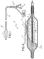
- a photodynamic therapy balloon catheter generally designated as 11, is generally illustrated in FIG. 1.
- the illustrated catheter includes a multilumen catheter tube 12, a proximal portion, generally designated as 13, and a distal portion generally designated as 14. Also included is a light transmission system including a light source 15.
- distal portion 14 includes an optical fiber 16.
- the optical fiber 16 is positioned interior to an inner tubular member 17.
- the inner member 17 is generally light-passing or optically clear.
- it will be made of a biocompatible polymer.
- examples include polyamides, polyurethanes, polyesters, polyolefins and the like.
- Specific examples include nylons, polyethylene, and the like.
- Suitable nylons include nylon 12, nylon 11, other nylon homopolymers and copolymers with other components.
- Grilamid (trademark) nylons and Vestamid (trademark) nylons are specific examples.
- the inner member 17 is cylindrically surrounded by a generally light-passing inflatable balloon member 18.
- Balloon 18 is in fluid-passing communication with a lumen within the catheter tube.
- Balloon member 18 is also made of a biocompatible polymer and typically can be made of polymers of the type used in manufacturing the inner member 17.
- a fluid injector assembly 19, as shown in Fig. 1, of generally known construction passes inflation fluid through the lumen into the inflatable balloon member 18.
- balloon member 18 is shown in an inflated state and for engagement with an inside wall of a vessel 27 such as a blood vessel or the like. Description herein will be with respect to blood vessels; nevertheless, it will be understood that the invention is applicable to use with respect to other vessels or internal body components.
- the balloon member 18 is inflated with generally light-passing or optically clear fluid material 20 such as saline solution or water. It will be appreciated that, with the balloon inflated as illustrated in Fig. 2, an annular chamber 21 is defined between the inner tubular member 17 and the balloon member 18. When the fluid material passes through the lumen, it enters into annular chamber 21, causing balloon member 18 to open up and move toward contact with the vessel wall 27.
- fluid material 20 such as saline solution or water.
- a photodynamic treatment fluid 23 in order to activate a photodynamic treatment fluid 23 (discussed in greater detail herein) more effectively, it must be illuminated more evenly and uniformly.
- cladding material 24 on the optical fiber 16 is removed at its distal portion, exposing an optical fiber core 26.
- an elongated light emanating area 28 is provided.
- the length of area 28 approximates the working length 29 of balloon member 18.
- the illuminating light from the elongated light-emanating area 28 radiates in a perpendicular or radial direction in relation to the longitudinal axis of the optical fiber core 26. This perpendicular or radial radiation of the illuminating light provides a cylindrical illumination pattern extending over the working area 29 of the balloon and the entire surface area of the treatment fluid 23, including its entire longitudinal extent.
- the optical fiber core 26 can be tapered such that it has a reducing thickness in the distal direction.
- any cladding remaining in the elongated area 28 could be tapered in the same direction.
- a gradient reduction in the thickness of the optical fiber component provides for the light which emanates along the length of the elongated light-emanating area 28 to illuminate with a higher degree of uniformity.
- the intensity of the light energy present in the optical fiber core 26 decreases in the distal direction, due to the greater longitudinal distance through which the light must pass at the more distal portions of the optical fiber.
- the greater longitudinal distances are combined with the shorter radial distances, and vice versa, to achieve a total light path (longitudinal plus radial) which is about the same throughout the light-emanating area, which allows the light energy emanating from the core 26 to be more uniform.
- the tapering of the optical fiber component can be effected through chemical etching or physical abrasion. It is further understood that the physical abrasion can be accomplished by using a gritty surface such as sand paper to longitudinally abrade the surface of the optical fiber component, whether such is carried out in a distally tapering or a right-cylindrical pattern.
- highly reflective material or particles are compounded with the inner member 17, fluid material 20, and/or balloon member 18. As the light encounters the highly reflective material, it reflects in different directions producing a uniform glow. This addition of the highly reflective particles to the above-mentioned elements results in the scattering and dispersing of the light, thereby uniformly lighting the cylindrical elongated light-emanating area 28 and the treatment fluid infused at the treatment site.
- reflective material 25a is in the form of particles compounded with the inner tubular member 17 such that light passing through the inner tubular member will be reflected by the reflective particles 25a. Either these particles can be loaded into the polymer such as at extrusion of the inner member 17, or they can be coated onto one or both of the surfaces of the tubular member.
- Suitable reflective material includes titanium dioxide (TiO 2 ) and silver, with titanium dioxide being preferred.
- TiO 2 titanium dioxide
- the presence of the reflective material causes the light emanating from the optical fiber to reflect and disperse at least along the entire length of the light-emanating area 28, producing a uniform cylindrically-shaped ring of illumination that delivers the light energy uniformly along the length of the vessel or the like at which photodynamic treatment fluid is located.
- the uniform light has the desirable effect of eliminating light energy "hot spots" and uneven activation of the treatment fluid.
- the second embodiment of the present invention calls for the presence of the reflective material 25b in the fluid material 20.
- Reflective material 25b is in the form of particulates suspended within the fluid material 20, resulting in the reflection off of these particles of the light emanating from the optical fiber 16.
- the thus reflective fluid filled within the annular chamber 21 fully surrounds the light-emanating area and provides a depth of reflective particles in the fluid through which the light must pass along its path to the balloon 18 and hence to the vessel wall. Reflection off the particles and the resulting light dispersion produces a uniform light having the previously mentioned desirable effects of eliminating the uneven activation of the treatment fluid which is generally along the outside surface of the balloon member 18.
- the third embodiment, illustrated in Fig. 4, is the preferred embodiment of the present invention and is generally similar to that of Fig. 2.
- the reflective material 25c is in the nature of highly reflective particles compounded with the material of the balloon member 18, for example either coated on the balloon member 18 or loaded into the polymer out of which the balloon member 18 is constructed. It will be appreciated that the loading is accomplished during the extrusion of the parison from which balloon member 18 is subsequently formed. The presence of the reflective material produces a reflecting and scattering effect.
- the inner tubular member 17 and the fluid material 20 in this embodiment are light-passing in order to allow light transmission from the optical fiber 16.
- the reflective particles 25c integrate the light along at least the treatment length and transmit a portion of the light energy to the vessel wall to be treated. This allows the light to be more uniform and even as it is transmitted through the balloon wall creating an even distribution of light energy to activate the treatment fluid 23 (photodynamic substance) already infused in or otherwise dispersed to the vessel wall, especially to the diseased area 22.
- the amount of compounding can be between about 5 and about 40 weight percent reflective material based on the total weight of the polymer. It is preferred that this ratio be in the range of about 10 to about 40 weight percent, most preferably between about 25 and about 35 percent by weight of the total weight of the polymer.
- An alternative approach for compounding the balloon member 18 or the inner member 17 with the reflective particles includes coextruding or otherwise positioning a layer of highly reflective material or particles between two layers of polymer. It has been noted that 90% light illumination uniformity can be achieved when compounding the fluid material 20 and/or balloon member 18 with the highly reflective material 25b or 25c, respectively.
- the light is integrated before it emanates from the balloon member 18 into the vessel wall.
- the balloon material semi-reflective and semi-transparent, one can achieve more uniformity along the cylindrical surface of the balloon, thereby optimizing the delivery of light to the treatment fluid 23 which has been absorbed into the vessel wall to be treated.
- coating of the inner member 17 or balloon member 18 can be achieved by known methods such as evaporation, sputtering, or ion bombardment of the reflective material. Such coating can be on the inside, the outside, or both the inside and outside of the inner member 17 or balloon member 18.
- the reflective material can be included in any one or a plurality of the inner member 17, balloon member 18, and fluid material 20, in any combination.
Landscapes
- Health & Medical Sciences (AREA)
- Engineering & Computer Science (AREA)
- Biomedical Technology (AREA)
- Life Sciences & Earth Sciences (AREA)
- Pathology (AREA)
- Radiology & Medical Imaging (AREA)
- Nuclear Medicine, Radiotherapy & Molecular Imaging (AREA)
- Animal Behavior & Ethology (AREA)
- General Health & Medical Sciences (AREA)
- Public Health (AREA)
- Veterinary Medicine (AREA)
- Biophysics (AREA)
- Radiation-Therapy Devices (AREA)
Applications Claiming Priority (2)
| Application Number | Priority Date | Filing Date | Title |
|---|---|---|---|
| US690329 | 1996-07-25 | ||
| US08/690,329 US5797868A (en) | 1996-07-25 | 1996-07-25 | Photodynamic therapy balloon catheter |
Publications (3)
| Publication Number | Publication Date |
|---|---|
| EP0820787A2 true EP0820787A2 (de) | 1998-01-28 |
| EP0820787A3 EP0820787A3 (de) | 1999-04-21 |
| EP0820787B1 EP0820787B1 (de) | 2005-05-18 |
Family
ID=24772043
Family Applications (1)
| Application Number | Title | Priority Date | Filing Date |
|---|---|---|---|
| EP97305543A Expired - Lifetime EP0820787B1 (de) | 1996-07-25 | 1997-07-24 | Ballonkatheter für die photodynamischen Therapie |
Country Status (4)
| Country | Link |
|---|---|
| US (1) | US5797868A (de) |
| EP (1) | EP0820787B1 (de) |
| CA (1) | CA2211243C (de) |
| DE (1) | DE69733297T2 (de) |
Cited By (4)
| Publication number | Priority date | Publication date | Assignee | Title |
|---|---|---|---|---|
| EP1109506A4 (de) * | 1998-08-06 | 2009-09-09 | Provectus Pharmatech Inc | Verbessertes verfahren zur gezielten lokalen krankheitsbehandlung |
| GB2459347A (en) * | 2008-04-23 | 2009-10-28 | Schlumberger Holdings | Running optical fibre in a well using fluid flow |
| WO2009130049A1 (en) * | 2008-04-25 | 2009-10-29 | Curalux Gbr | Light-based method for the endovascular treatment of pathologically altered blood vessels |
| US8114068B2 (en) | 2006-10-17 | 2012-02-14 | Dornier Medtech Laser Gmbh | Light guide |
Families Citing this family (35)
| Publication number | Priority date | Publication date | Assignee | Title |
|---|---|---|---|---|
| AU9294298A (en) * | 1997-08-25 | 1999-03-16 | Advanced Photodynamic Technologies, Inc. | Treatment device for topical photodynamic therapy and method of making same |
| FR2767703A1 (fr) * | 1997-09-04 | 1999-03-05 | Medlight Sa | Dispositif pour l'irradiation de cavites interieures de l'organisme |
| US6267747B1 (en) | 1998-05-11 | 2001-07-31 | Cardeon Corporation | Aortic catheter with porous aortic root balloon and methods for inducing cardioplegic arrest |
| US6440102B1 (en) * | 1998-07-23 | 2002-08-27 | Durect Corporation | Fluid transfer and diagnostic system for treating the inner ear |
| WO2000041726A2 (en) | 1999-01-15 | 2000-07-20 | Light Sciences Corporation | Noninvasive vascular therapy |
| US6454789B1 (en) * | 1999-01-15 | 2002-09-24 | Light Science Corporation | Patient portable device for photodynamic therapy |
| US6602274B1 (en) * | 1999-01-15 | 2003-08-05 | Light Sciences Corporation | Targeted transcutaneous cancer therapy |
| US6159236A (en) * | 1999-01-28 | 2000-12-12 | Advanced Photodynamic Technologies, Inc. | Expandable treatment device for photodynamic therapy and method of using same |
| US6263236B1 (en) | 1999-11-29 | 2001-07-17 | Illumenex Corporation | Non-occlusive expandable catheter |
| US20020049247A1 (en) | 2000-01-12 | 2002-04-25 | Chen James C. | Novel treatment for eye disease |
| US6749623B1 (en) * | 2000-03-31 | 2004-06-15 | Richard A Hsi | Method and apparatus for catheter phototherapy with dose sensing |
| US6761708B1 (en) | 2000-10-31 | 2004-07-13 | Advanced Cardiovascular Systems, Inc. | Radiopaque marker for a catheter and method of making |
| DE10125152A1 (de) * | 2001-05-22 | 2002-12-12 | Schott Glas | Lichtwellenleiter |
| JP2003116869A (ja) * | 2001-10-18 | 2003-04-22 | Honda Seiki Kk | 超音波治療装置および超音波診断装置 |
| JP2006507016A (ja) * | 2002-02-05 | 2006-03-02 | ファーマサイクリックス・インコーポレーテッド | 円錐形拡散システムを使用する光送出デバイス、およびその形成方法 |
| US20040236366A1 (en) * | 2002-05-16 | 2004-11-25 | Kennedy Kenneth C. | Non-buckling balloon catheter |
| US20030236495A1 (en) * | 2002-05-16 | 2003-12-25 | Kennedy Kenneth C. | Non-buckling balloon catheter |
| US7131963B1 (en) * | 2002-06-27 | 2006-11-07 | Advanced Cardiovascular Systems, Inc. | Catheters and methods of using catheters |
| EP1526801A2 (de) * | 2002-08-05 | 2005-05-04 | Miravant Medical Technologies Inc. | Katheter für diagnose und zur behandlung von erkrankten blutgefässe |
| WO2004012805A2 (en) | 2002-08-05 | 2004-02-12 | Miravant Medical Technologies | Light delivery catheter |
| US20070282301A1 (en) * | 2004-02-26 | 2007-12-06 | Segalescu Victor A | Dilatation Balloon Catheter Including External Means For Endoluminal Therapy And For Drug Activation |
| WO2006024038A2 (en) * | 2004-08-27 | 2006-03-02 | Codman & Shurtleff | Light-based implant for treating alzheimer’s disease |
| US20060173514A1 (en) * | 2005-02-02 | 2006-08-03 | Advanced Photodynamic Technologies, Inc. | Wound treatment device for photodynamic therapy and method of using same |
| US7288108B2 (en) * | 2005-03-14 | 2007-10-30 | Codman & Shurtleff, Inc. | Red light implant for treating Parkinson's disease |
| USRE47266E1 (en) | 2005-03-14 | 2019-03-05 | DePuy Synthes Products, Inc. | Light-based implants for treating Alzheimer's disease |
| US7351253B2 (en) * | 2005-06-16 | 2008-04-01 | Codman & Shurtleff, Inc. | Intranasal red light probe for treating Alzheimer's disease |
| US20070038203A1 (en) * | 2005-07-11 | 2007-02-15 | Mcintyre Jon T | Materials and methods for ablation of the endometrium |
| WO2007081530A2 (en) * | 2006-01-03 | 2007-07-19 | Med Institute, Inc. | Endoluminal medical device for local delivery of cathepsin inhibitors |
| US20080306441A1 (en) * | 2007-04-10 | 2008-12-11 | Wilson-Cook Medical Inc. | Non-buckling balloon catheter with spring loaded floating flexible tip |
| US7828840B2 (en) * | 2007-11-15 | 2010-11-09 | Med Institute, Inc. | Medical devices and methods for local delivery of angiotensin II type 2 receptor antagonists |
| US9320914B2 (en) | 2008-03-03 | 2016-04-26 | DePuy Synthes Products, Inc. | Endoscopic delivery of red/NIR light to the subventricular zone |
| US20100198316A1 (en) * | 2009-02-04 | 2010-08-05 | Richard Toselli | Intracranial Red Light Treatment Device For Chronic Pain |
| WO2016081594A1 (en) * | 2014-11-19 | 2016-05-26 | The General Hospital Corporation | System and method for photo-dynamic procedure |
| CN116471977A (zh) * | 2020-09-28 | 2023-07-21 | 波士顿科学国际有限公司 | 用于定位体腔的装置、系统和方法 |
| CN119896545B (zh) * | 2025-03-27 | 2025-09-26 | 深圳市开颜医疗器械有限公司 | 定位体内腔道组织的装置 |
Citations (2)
| Publication number | Priority date | Publication date | Assignee | Title |
|---|---|---|---|---|
| DE3323365A1 (de) | 1982-09-04 | 1984-03-08 | Gesellschaft für Strahlen- und Umweltforschung mbH, 8000 München | Verfahren und vorrichtung zur ausleuchtung von hohlraeumen |
| DE3941705A1 (de) | 1989-12-18 | 1991-06-20 | Strahlen Umweltforsch Gmbh | Vorrichtung zur isotropen bestrahlung von hohlraeumen von kugelaehnlicher gestalt |
Family Cites Families (17)
| Publication number | Priority date | Publication date | Assignee | Title |
|---|---|---|---|---|
| US4636195A (en) * | 1982-04-02 | 1987-01-13 | Harvey Wolinsky | Method and apparatus for removing arterial constriction |
| GB2154761A (en) * | 1984-02-21 | 1985-09-11 | Quentron Optics Pty Ltd | Diffusive optical fibre termination |
| US4878492A (en) * | 1987-10-08 | 1989-11-07 | C. R. Bard, Inc. | Laser balloon catheter |
| GB8817032D0 (en) * | 1988-07-18 | 1988-08-24 | Rowland A C | Light delivery system |
| DE3915636C1 (de) * | 1989-05-12 | 1990-04-26 | Sass, Wolfgang, Dr. | |
| JP2882814B2 (ja) * | 1989-08-24 | 1999-04-12 | 株式会社エス・エル・ティ・ジャパン | レーザ光の照射装置 |
| US5049132A (en) * | 1990-01-08 | 1991-09-17 | Cordis Corporation | Balloon catheter for delivering therapeutic agents |
| ES2067013T3 (es) * | 1990-01-09 | 1995-03-16 | Ciba Geigy Ag | Dispositivo para la irradiacion de los bronquios de un paciente para una terapia fotodinamica. |
| US5236413B1 (en) * | 1990-05-07 | 1996-06-18 | Andrew J Feiring | Method and apparatus for inducing the permeation of medication into internal tissue |
| CA2081896A1 (en) * | 1990-06-15 | 1991-12-16 | James E. Shapland | Drug delivery apparatus and method |
| US5087243A (en) * | 1990-06-18 | 1992-02-11 | Boaz Avitall | Myocardial iontophoresis |
| US5169395A (en) * | 1991-04-26 | 1992-12-08 | Pdt Cardiovascular, Inc. | Laser delivery system |
| US5213576A (en) * | 1991-06-11 | 1993-05-25 | Cordis Corporation | Therapeutic porous balloon catheter |
| US5318531A (en) * | 1991-06-11 | 1994-06-07 | Cordis Corporation | Infusion balloon catheter |
| US5303324A (en) * | 1992-10-29 | 1994-04-12 | American Cyanamid Company | Method and apparatus for providing controlled light distribution from a cylindrical fiberoptic diffuser |
| US5415654A (en) * | 1993-10-05 | 1995-05-16 | S.L.T. Japan Co., Ltd. | Laser balloon catheter apparatus |
| US5505700A (en) * | 1994-06-14 | 1996-04-09 | Cordis Corporation | Electro-osmotic infusion catheter |
-
1996
- 1996-07-25 US US08/690,329 patent/US5797868A/en not_active Expired - Lifetime
-
1997
- 1997-07-23 CA CA002211243A patent/CA2211243C/en not_active Expired - Lifetime
- 1997-07-24 EP EP97305543A patent/EP0820787B1/de not_active Expired - Lifetime
- 1997-07-24 DE DE69733297T patent/DE69733297T2/de not_active Expired - Lifetime
Patent Citations (2)
| Publication number | Priority date | Publication date | Assignee | Title |
|---|---|---|---|---|
| DE3323365A1 (de) | 1982-09-04 | 1984-03-08 | Gesellschaft für Strahlen- und Umweltforschung mbH, 8000 München | Verfahren und vorrichtung zur ausleuchtung von hohlraeumen |
| DE3941705A1 (de) | 1989-12-18 | 1991-06-20 | Strahlen Umweltforsch Gmbh | Vorrichtung zur isotropen bestrahlung von hohlraeumen von kugelaehnlicher gestalt |
Cited By (8)
| Publication number | Priority date | Publication date | Assignee | Title |
|---|---|---|---|---|
| EP1109506A4 (de) * | 1998-08-06 | 2009-09-09 | Provectus Pharmatech Inc | Verbessertes verfahren zur gezielten lokalen krankheitsbehandlung |
| US8114068B2 (en) | 2006-10-17 | 2012-02-14 | Dornier Medtech Laser Gmbh | Light guide |
| GB2459347A (en) * | 2008-04-23 | 2009-10-28 | Schlumberger Holdings | Running optical fibre in a well using fluid flow |
| GB2459347B (en) * | 2008-04-23 | 2010-09-22 | Schlumberger Holdings | System and method for deploying optical fiber |
| US7946350B2 (en) | 2008-04-23 | 2011-05-24 | Schlumberger Technology Corporation | System and method for deploying optical fiber |
| WO2009130049A1 (en) * | 2008-04-25 | 2009-10-29 | Curalux Gbr | Light-based method for the endovascular treatment of pathologically altered blood vessels |
| US9149334B2 (en) | 2008-04-25 | 2015-10-06 | Dornier Medtech Laser Gmbh | Light-based method for the endovascular treatment of pathologically altered blood vessels |
| US9168098B2 (en) | 2008-04-25 | 2015-10-27 | Dornier Medtech Laser Gmbh | Light-based method for the endovascular treatment of pathologically altered blood vessels |
Also Published As
| Publication number | Publication date |
|---|---|
| DE69733297D1 (de) | 2005-06-23 |
| EP0820787A3 (de) | 1999-04-21 |
| CA2211243A1 (en) | 1998-01-25 |
| DE69733297T2 (de) | 2006-03-09 |
| CA2211243C (en) | 2006-04-04 |
| US5797868A (en) | 1998-08-25 |
| EP0820787B1 (de) | 2005-05-18 |
Similar Documents
| Publication | Publication Date | Title |
|---|---|---|
| US5797868A (en) | Photodynamic therapy balloon catheter | |
| EP0820786B1 (de) | Ballonkatheter mit mikroporöser Membran in der photodynamischen Therapie | |
| US5908415A (en) | Phototherapy methods and apparatus | |
| US6146409A (en) | Therapeutic methods and devices for irradiating columnar environments | |
| AU2001290540B2 (en) | Photodynamic therapy light diffuser | |
| EP0902653B1 (de) | Ballonkatheter für photodynamische therapie | |
| US5330465A (en) | Continuous gradient cylindrical diffusion tip for optical fibers and method for using | |
| US6270492B1 (en) | Phototherapeutic apparatus with diffusive tip assembly | |
| AU725320B2 (en) | Phototherapeutic apparatus | |
| US5643253A (en) | Phototherapy apparatus with integral stopper device | |
| AU2001290540A1 (en) | Photodynamic therapy light diffuser | |
| GB2208805A (en) | Laser catheter | |
| US20050128742A1 (en) | Light generating device that self centers within a lumen to render photodynamic therapy | |
| EP1527798A2 (de) | Diffusionspritzskörper. |
Legal Events
| Date | Code | Title | Description |
|---|---|---|---|
| PUAI | Public reference made under article 153(3) epc to a published international application that has entered the european phase |
Free format text: ORIGINAL CODE: 0009012 |
|
| AK | Designated contracting states |
Kind code of ref document: A2 Designated state(s): BE CH DE FR GB IE IT LI NL |
|
| TPAD | Observations filed by third parties |
Free format text: ORIGINAL CODE: EPIDOS TIPA |
|
| PUAL | Search report despatched |
Free format text: ORIGINAL CODE: 0009013 |
|
| AK | Designated contracting states |
Kind code of ref document: A3 Designated state(s): AT BE CH DE DK ES FI FR GB GR IE IT LI LU MC NL PT SE |
|
| 17P | Request for examination filed |
Effective date: 19991001 |
|
| AKX | Designation fees paid |
Free format text: BE CH DE FR GB IE IT LI NL |
|
| 17Q | First examination report despatched |
Effective date: 20040319 |
|
| GRAP | Despatch of communication of intention to grant a patent |
Free format text: ORIGINAL CODE: EPIDOSNIGR1 |
|
| GRAS | Grant fee paid |
Free format text: ORIGINAL CODE: EPIDOSNIGR3 |
|
| GRAA | (expected) grant |
Free format text: ORIGINAL CODE: 0009210 |
|
| AK | Designated contracting states |
Kind code of ref document: B1 Designated state(s): BE CH DE FR GB IE IT LI NL |
|
| REG | Reference to a national code |
Ref country code: GB Ref legal event code: FG4D |
|
| REG | Reference to a national code |
Ref country code: CH Ref legal event code: EP |
|
| REG | Reference to a national code |
Ref country code: IE Ref legal event code: FG4D |
|
| REF | Corresponds to: |
Ref document number: 69733297 Country of ref document: DE Date of ref document: 20050623 Kind code of ref document: P |
|
| REG | Reference to a national code |
Ref country code: CH Ref legal event code: NV Representative=s name: E. BLUM & CO. PATENTANWAELTE |
|
| PLBE | No opposition filed within time limit |
Free format text: ORIGINAL CODE: 0009261 |
|
| STAA | Information on the status of an ep patent application or granted ep patent |
Free format text: STATUS: NO OPPOSITION FILED WITHIN TIME LIMIT |
|
| ET | Fr: translation filed | ||
| 26N | No opposition filed |
Effective date: 20060221 |
|
| REG | Reference to a national code |
Ref country code: CH Ref legal event code: PFA Owner name: CORDIS CORPORATION Free format text: CORDIS CORPORATION#14201 N.W. 60TH AVENUE#MIAMI LAKES FLORIDA 33014 (US) -TRANSFER TO- CORDIS CORPORATION#14201 N.W. 60TH AVENUE#MIAMI LAKES FLORIDA 33014 (US) |
|
| REG | Reference to a national code |
Ref country code: FR Ref legal event code: PLFP Year of fee payment: 20 |
|
| PGFP | Annual fee paid to national office [announced via postgrant information from national office to epo] |
Ref country code: NL Payment date: 20160726 Year of fee payment: 20 |
|
| PGFP | Annual fee paid to national office [announced via postgrant information from national office to epo] |
Ref country code: GB Payment date: 20160727 Year of fee payment: 20 Ref country code: IT Payment date: 20160722 Year of fee payment: 20 Ref country code: CH Payment date: 20160727 Year of fee payment: 20 Ref country code: DE Payment date: 20160726 Year of fee payment: 20 Ref country code: IE Payment date: 20160726 Year of fee payment: 20 |
|
| PGFP | Annual fee paid to national office [announced via postgrant information from national office to epo] |
Ref country code: FR Payment date: 20160726 Year of fee payment: 20 |
|
| PGFP | Annual fee paid to national office [announced via postgrant information from national office to epo] |
Ref country code: BE Payment date: 20160727 Year of fee payment: 20 |
|
| REG | Reference to a national code |
Ref country code: DE Ref legal event code: R071 Ref document number: 69733297 Country of ref document: DE |
|
| REG | Reference to a national code |
Ref country code: NL Ref legal event code: MK Effective date: 20170723 |
|
| REG | Reference to a national code |
Ref country code: CH Ref legal event code: PL |
|
| REG | Reference to a national code |
Ref country code: GB Ref legal event code: PE20 Expiry date: 20170723 |
|
| REG | Reference to a national code |
Ref country code: IE Ref legal event code: MK9A |
|
| REG | Reference to a national code |
Ref country code: BE Ref legal event code: MK Effective date: 20170724 |
|
| PG25 | Lapsed in a contracting state [announced via postgrant information from national office to epo] |
Ref country code: IE Free format text: LAPSE BECAUSE OF EXPIRATION OF PROTECTION Effective date: 20170724 Ref country code: GB Free format text: LAPSE BECAUSE OF EXPIRATION OF PROTECTION Effective date: 20170723 |