EP0820832B1 - Durch einen Motor angetriebener Schweisseinrichtungsgenerator - Google Patents
Durch einen Motor angetriebener Schweisseinrichtungsgenerator Download PDFInfo
- Publication number
- EP0820832B1 EP0820832B1 EP97117658A EP97117658A EP0820832B1 EP 0820832 B1 EP0820832 B1 EP 0820832B1 EP 97117658 A EP97117658 A EP 97117658A EP 97117658 A EP97117658 A EP 97117658A EP 0820832 B1 EP0820832 B1 EP 0820832B1
- Authority
- EP
- European Patent Office
- Prior art keywords
- output
- voltage
- welding
- circuit
- current
- Prior art date
- Legal status (The legal status is an assumption and is not a legal conclusion. Google has not performed a legal analysis and makes no representation as to the accuracy of the status listed.)
- Expired - Lifetime
Links
- 238000003466 welding Methods 0.000 claims description 124
- 230000001105 regulatory effect Effects 0.000 claims description 10
- 230000001629 suppression Effects 0.000 claims description 9
- 230000001276 controlling effect Effects 0.000 claims description 4
- 238000010586 diagram Methods 0.000 description 8
- 239000003990 capacitor Substances 0.000 description 6
- 229920002678 cellulose Polymers 0.000 description 6
- 239000001913 cellulose Substances 0.000 description 6
- 238000005516 engineering process Methods 0.000 description 6
- 238000009499 grossing Methods 0.000 description 4
- 239000010953 base metal Substances 0.000 description 3
- 230000007547 defect Effects 0.000 description 3
- 230000006866 deterioration Effects 0.000 description 3
- 230000003247 decreasing effect Effects 0.000 description 2
- 238000001514 detection method Methods 0.000 description 2
- 238000000034 method Methods 0.000 description 2
- 238000004804 winding Methods 0.000 description 2
- 238000010276 construction Methods 0.000 description 1
- 238000001816 cooling Methods 0.000 description 1
- 230000008021 deposition Effects 0.000 description 1
- 230000000694 effects Effects 0.000 description 1
- 238000010304 firing Methods 0.000 description 1
- 238000004519 manufacturing process Methods 0.000 description 1
- 238000012544 monitoring process Methods 0.000 description 1
- 230000002035 prolonged effect Effects 0.000 description 1
- 239000004065 semiconductor Substances 0.000 description 1
- 239000000779 smoke Substances 0.000 description 1
Images


Classifications
-
- B—PERFORMING OPERATIONS; TRANSPORTING
- B23—MACHINE TOOLS; METAL-WORKING NOT OTHERWISE PROVIDED FOR
- B23K—SOLDERING OR UNSOLDERING; WELDING; CLADDING OR PLATING BY SOLDERING OR WELDING; CUTTING BY APPLYING HEAT LOCALLY, e.g. FLAME CUTTING; WORKING BY LASER BEAM
- B23K9/00—Arc welding or cutting
- B23K9/10—Other electric circuits therefor; Protective circuits; Remote controls
- B23K9/1006—Power supply
- B23K9/1043—Power supply characterised by the electric circuit
-
- B—PERFORMING OPERATIONS; TRANSPORTING
- B23—MACHINE TOOLS; METAL-WORKING NOT OTHERWISE PROVIDED FOR
- B23K—SOLDERING OR UNSOLDERING; WELDING; CLADDING OR PLATING BY SOLDERING OR WELDING; CUTTING BY APPLYING HEAT LOCALLY, e.g. FLAME CUTTING; WORKING BY LASER BEAM
- B23K9/00—Arc welding or cutting
- B23K9/10—Other electric circuits therefor; Protective circuits; Remote controls
- B23K9/1006—Power supply
- B23K9/1043—Power supply characterised by the electric circuit
- B23K9/1056—Power supply characterised by the electric circuit by using digital means
Definitions
- This invention relates to an engine driven arc welder or welding machine in which the external output characteristic is caused to have constant current characteristic.
- FIG. 10 a chopper circuit for providing general constant current characteristic is constituted. Namely, an output from generator 32 connected to engine 31 is rectified by rectifier 33 and is then smoothed by smoothing capacitor 34 so that it is caused to be power having lower impedance even when high speed operation of transistor is carried out. Switching transistor 35 carries out ON/OFF operation of power thus obtained at higher frequency and by large current.
- Reactor 36 suppresses sudden increase or decrease of current and smoothes output caused to undergo switching by switching transistor 35, thus to stabilize the welding condition.
- reference numerals 37, 38 denote welding terminals
- reference numeral 39 denotes a current detector
- reference numeral 40 denotes a constant current control section
- reference numeral 41 denotes a transistor drive section for driving switching transistor 35.
- EP-0 536 397A1 discloses an arc welding apparatus wherein the welding current is supplied by a d.c. generator having a drooping voltage-current characteristic. When during the welding operation the voltage across the d.c. generator drops below the voltage of a battery, the welding current is supported by the battery in order to provide a large short-circuit current. A voltage regulator sensing the voltage accross the terminals of the battery is provided to control the output voltage of the d.c. generator. There are no means for sensing and processing the welding current in order to improve the welding operation.
- An object of this invention as defined in claim 1 is to provide an engine driven arc welder having constant current characteristic, which is permitted to limit welding output to prevent overload in such a case that welding output is placed in overload state by the welding work condition.
- an engine driven arc welder comprising a welding generator driven by the engine to form an a.c. output, an automatic voltage regulating circuit for regulating an a.c. output voltage of the welding generator so that it becomes equal to a fixed value, a rectifying circuit for converting the a.c. output of the welding generator into a d.c., a switching circuit for allowing the d.c.
- a welding current detector for detecting an output current of the switching circuit
- a constant current control circuit for applying a control signal to the switching circuit in response to the detected current of the welding current detector to control the ON-period thereof so that it becomes equal to a fixed value, characterized by the provision of a frequency detecting circuit for detecting a frequency of an a.c.
- a frequency-voltage characteristic circuit for controlling the welding generator so as to output a voltage of a fixed value when the detected frequency of the frequency detecting circuit is a predetermined value or more, and a voltage of a value proportional to frequency when that detected frequency is less than the predetermined value
- a voltage detecting circuit for detecting an output voltage of the welding generator
- an output suppression circuit for comparing the detected voltage of the voltage detection circuit with a reference voltage set in advance to deliver a signal to suppress a welding output to the constant current control circuit when the detected voltage is lower than the reference voltage, thus to carry out switching control of the switching circuit by an output of the output suppression circuit.
- FIG. 1 is an electric circuit diagram showing, partially in a block form, a first embodiment of an engine driven arc welder of this invention
- FIG. 2 is a graph showing power characteristic curve in which arc current I is taken on the abscissa and arc voltage V is taken on the ordinate.
- a generator 2 for welding is connected to an engine 1. An output from the welding generator 2 is rectified by a rectifier 3. Then, by a smoothing capacitor 4, an output of the rectifier 3 is caused to be power having low impedance even when high speed operation of transistor is carried out.
- Reference numeral 5 denotes a switching transistor for performing ON/OFF operation at higher frequency and by large current
- reference numeral 6 denotes a reactor for suppressing sudden increase or decrease of current to smooth an output caused to undergo switching by switching transistor 5, thus to stabilize the welding condition
- reference numeral 9 denotes a freewheeling (fly-back) diode circuit section for forming a closed circuit including reactor, arc and freewheeling diode for maintaining arc current when switching transistor 5 is in OFF state.
- Reference numerals 7, 8 denote an output (welding) terminal
- reference numeral 10 denotes a current detector for detecting a current at the welding terminal.
- Reference numeral 11 denotes a switching element drive section for controlling switching transistor 5
- reference numeral 12 denotes a comparison control circuit for comparing a reference voltage at the point A and an output voltage signal of current detector 10 to send a signal to switching element drive section 11 so that they have the same voltage.
- Reference numeral 13 denotes a reference voltage source for delivering reference voltage to the point A, which is supplied with power from winding wound within generator 2 to form an output of a predetermined voltage
- reference numeral 14 denotes a variable resistor for changing an output voltage signal of current detector 10 to arbitrarily adjust set current (output voltage)
- D 1 denotes a rectifying diode.
- the circuit between output terminal 7 and comparison control circuit 12 is a current increase circuit for increase-controlling welding current. It is to be noted that reference voltage source 13 may be supplied with power from between smoothing capacitor 4 and switching transistor 5, or from battery (not shown).
- an output of welding generator 2 is provided, by operation of the engine, across output terminals 7, 8 via rectifier 3, smoothing capacitor 4, switching transistor 5 and reactor 6.
- current detector 10 detects welding current to output voltage signal to send it to comparison control circuit 12.
- This comparison control circuit 12 compares a reference voltage obtained by dividing, by using resistors r 4 and r 5 , a voltage delivered from reference voltage source 13 and the voltage signal to send a signal to switching element drive section 11 so that the both values take the same voltage to thereby carry out constant current control so that set value is kept at all times. In such a state, welding work is continued.
- this set voltage can be arbitrarily changed by manually operating variable resistor 14.
- the variable resistor 14 is not directed to vary the welding voltage but to adjust the welding current.
- comparison control circuit 12 has, as reference voltage, a voltage at the point A obtained by dividing output voltage of reference voltage source 13 by resistors r 4 and r 5 .
- reference voltage a voltage at the point A obtained by dividing output voltage of reference voltage source 13 by resistors r 4 and r 5 .
- a voltage obtained by dividing its voltage by resistors r 1 and r 2 is delivered to rectifying diode D 1 and amplifying transistor Tr 1 .
- amplifying transistor Tr 1 is in conductive state, so a current passing through resistor r 4 , amplifying transistor Tr 1 and resistor r 3 flows from reference voltage source 13.
- the power characteristic in the load voltage range lower than V 1 is as follows. Namely, when an operator shortens the distance between welding rod and base metal during welding work to thereby shorten the arc length, or droplet of the welding rod is developed so that the distance therebetween is narrowed, so arc length is similarly shortened, the arc voltage is lowered. Accordingly, voltage across output terminal 7 and earth is proportionally lowered.
- voltage V 1 is set to a value in the vicinity of arc voltage as shown in FIG. 2, a voltage delivered to amplifying transistor Tr 1 is also lowered by the voltage proportionally lowering. For this reason, conductive resistance of amplifying transistor Tr 1 becomes large and voltage drop of resistor r 4 becomes small. Accordingly, potential at the point A is elevated.
- FIG. 3 is a block diagram showing a second embodiment of an engine driven arc welder with load limiting function according to this invention.
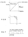
- FIG. 4 is an engine output-rotation number curve showing the relationship between engine output and engine rotation number.
- FIG. 5 shows FV characteristic curve of an automatic voltage regulating circuit.
- FIG. 6 shows a welding output characteristic according to this embodiment (slanting portion is excluded from the effective region).
- FIG. 7 shows ON/OFF operation of switching element.
- Welding generator 2 is connected to engine 1.
- the welding generator 2 is regulated by automatic voltage regulating circuit (AVR) 14 so that output voltage of generator is fixed.
- A.C. power by welding generator 2 is rectified into d.c. by rectifier 3.
- the rectifier output is smoothed by capacitor 4.
- Reference numeral 5 denotes switching element which carries out ON/OFF operation
- reference numeral 6 denotes reactor
- reference numeral 9 denotes freewheeling diode (fly-back diode) for maintaining arc
- reference numeral 10 denotes a welding current detector.
- Automatic voltage regulating circuit 14 has FV characteristic such that in the case where frequency of a.c. output of welding generator 2 is lowered to a value less than fixed frequency, output voltage of generator is lowered.
- Voltage detecting section 17 is connected to d.c. power supply section which has rectified a.c. power from welding generator 2. This detecting section 17 sends a detected voltage to output suppression section 18. When a detected voltage is less than a certain set voltage, the output suppression section 18 sends an output suppression signal proportional to lowering of voltage to constant current characteristic control section 15. At this time, voltage detecting section 17 may detect a.c. output voltage of welding generator 2. In addition, welding current detector 10 is also connected to constant current characteristic control section 15.
- Winding for delivering drive power to switching element drive section 16 is wound on stator of welding generator 2. Namely, there is provided a configuration to control switching element drive section 16 by control signal from constant current characteristic control section 15 thus to allow switching element 5 to be turned ON or OFF.
- constant current characteristic control section 15 becomes operative so that the detected welding current is always in correspondence with set current to control switching element drive section 16 to adjust ON period of switching element 5 so that a fixed current is provided.
- the relationship between engine output and engine rotation number has a characteristic (governer characteristic) as shown in FIG. 4. It is now assumed that the engine is carrying out no-load operation and its rotation number is no-load rotation number (a). When load is applied to engine 1, the engine governer attempts to maintain rotation number with increase of load, but the engine rotation number is lowered by the characteristic. Thus, that engine rotation number is lowered to maximum output rotation number (c) through rated output rotation number (b). When load is further applied to the engine 1 so that there results overload state, the engine rotation number is lowered from the point (c) and the engine output is also lowered. In the case where the welding output has been placed in overload state by making use of the characteristic, when the engine rotation number is lowered, and frequency of a.c.
- power supply voltage of the welding generator directly coupled to the engine is also lowered, so that frequency is lowered to less than frequency set in advance, power supply voltage of the welding generator is lowered by the FV characteristic of the automatic voltage regulating circuit 14. That voltage is detected by voltage detecting section 17 to send detected voltage to output suppression section 18. In the case where the detected voltage is lower than a voltage set in advance within the output suppresion section 15, an output suppression signal is given to constant current characteristic control section 15 so as to suppress welding output.
- switching element drive section 16 is controlled to shorten ON period of switching element 5 which performs operation shown in FIG. 7 in dependency upon lowering of voltage.
- welding output point is moved from a to b in the output characteristic without outputting overload region (slanting line portion) of FIG. 6.
- engine 1, welding generator 2, rectifier 3 and capacitor 4, etc. can become compact without requiring those components to have high performance.
- the engine can be rotated in reasonable state without excessively lowering rotation number of the engine.
- performance of the engine can be sufficiently exhibited and durability of the engine can be improved.
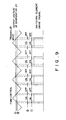
- Voltage detecting section 17 detects that voltage to send detected voltage to reference voltage control section 21 to compare it with voltage set within reference voltage control section 21. If this detected voltage is low, a signal to shift downwardly the level of reference voltage is sent to reference voltage section 22. As a result, that signal is outputted as a new reference voltage.
- Reference voltage outputted from reference voltage section 22 is inputted to comparator 23 together with comparison voltage proportional to welding current, at which they are compared with each other. When reference voltage is lowered, comparator 23 outputs output voltage in a direction to shift upwardly its level to shorten ON period of FIG.
- reference numeral 24 denotes a PWM control section
- reference numeral 25 denotes a triangular wave oscillator.
- output above the constant power characteristic represents overload state, and corresponds to slanting line portion of FIG. 6.
- welding output characteristic depicts output characteristic except for slanting line of FIG. 6 and limits load so that there results no overload state.
Landscapes
- Engineering & Computer Science (AREA)
- Physics & Mathematics (AREA)
- Plasma & Fusion (AREA)
- Mechanical Engineering (AREA)
- Arc Welding Control (AREA)
Claims (3)
- Motorbetriebener Lichtbogenschweißer, enthaltend einen Schweißgenerator (2), welcher von einem Motor (1) zur Erzeugung eines Wechselstroms angetrieben wird, eine automatische Spannungsregelungs-Schaltung (14) zur derartigen Regelung der Wechseistromabgabe des genannten Schweißgenerators (2), dass sie einen festen Wert annimmt, einen Gleichrichter (3) zur Umwandlung des Wechselstroms des genannten Schweißgenerators (2) in einen Gleichstrom, einen Umschaltkreis (5), mit dem die von dem genannten Gleichrichter (3) abgegebene Gleichspannung einer Schaltkontrolle unterzogen werden kann, um an einem Schweißterminal (7) eine schaltgeregelte Ausgangsgröße zu erzeugen; einen Schweißstromdetektor (10) zur Detektion eines Ausgangsstromes des genannten Umschaltkreises; und eine Konstantstrom-Regelungsschaltung (15) zur Abgabe eines Regelungssignals an den genannten Umschaltkreis in Reaktion auf einen detektierten Strom vom genannten Schweißstromdetektor (10), um die AN-Periode des genannten Umschaltkreises derart zu regeln, dass der Ausgangsstrom des genannten Schweißterminals (7) einen festen Wert annimmt,
dadurch gekennzeichnet, dass der motorbetriebene Lichtbogenschweißer enthält:eine Frequenz-Detektionsschaltung (in 14) zur Detektion einer Frequenz des Wechselstroms des genannten Schweißgenerators (2);eine Schaltung mit Frequenz-Spannungs-Charakteristik (in 14) für eine derartige Kontrolle des genannten Schweißgenerators (2), dass eine Spannung mit einem festen Wert ausgegeben wird, wenn die detektierte Frequenz der genannten Frequenz-Detektionsschaltung einen vorgegebenen Wert oder mehr besitzt, sowie eine Spannung proportional zur Frequenz, wenn die detektierte Frequenz weniger als der vorgegebene Wert beträgt;eine Detektionsschaltung (17) für Generatorausgangsspannung, um eine Ausgangsspannung des genannten Schweißgenerators (2) zu detektieren; undeine Ausgangs-Unterdrückungsschaltung (18) zum Vergleichen der detektierten Spannung von der genannten Detektionsschaltung (17) für Generatorausgangsspannung mit einer im voraus festgelegten Referenzspannung, um, wenn die detektierte Spannung geringer als die Referenzspannung ist, ein Signal zur Unterdrückung einer zum Schweißen bestimmten Abgabe an die genannte Konstantstrom-Regelungsschaltung (15) abzugeben, so dass auf diese Weise eine Schaltregelung des genannten Umschaltkreises (5) durch den Ausgang der genannten Ausgangs-Unterdrückungsschaltung (18) ausgeführt wird. - Lichtbogenschweißer nach Anspruch 1, wobei der Umschaltkreis (5) unter Verwendung von mindestens einem Transistor realisiert wird.
- Lichtbogenschweißer nach Anspruch 1 oder 2, wobei die genannte Konstantstrom-Regelungsschaltung (15) eine Pulsweitenmodulation zum Zwecke der Unterdrückungsregelung der Länge der AN-Periode des genannten Umschaltkreises (5) ausführt.
Applications Claiming Priority (7)
| Application Number | Priority Date | Filing Date | Title |
|---|---|---|---|
| JP259578/93 | 1993-10-18 | ||
| JP25957893A JP2684320B2 (ja) | 1993-10-18 | 1993-10-18 | エンジン駆動形アーク溶接機 |
| JP25957893 | 1993-10-18 | ||
| JP70632/93 | 1993-12-28 | ||
| JP7063293U JP2567726Y2 (ja) | 1993-12-28 | 1993-12-28 | 負荷制限装置付エンジン駆動アーク溶接機 |
| JP7063293 | 1993-12-28 | ||
| EP94116273A EP0648569B1 (de) | 1993-10-18 | 1994-10-15 | Lichtbogenschweissen mit einem die Leistung versorgenden Motor |
Related Parent Applications (1)
| Application Number | Title | Priority Date | Filing Date |
|---|---|---|---|
| EP94116273A Division EP0648569B1 (de) | 1993-10-18 | 1994-10-15 | Lichtbogenschweissen mit einem die Leistung versorgenden Motor |
Publications (2)
| Publication Number | Publication Date |
|---|---|
| EP0820832A1 EP0820832A1 (de) | 1998-01-28 |
| EP0820832B1 true EP0820832B1 (de) | 2000-04-26 |
Family
ID=26411765
Family Applications (2)
| Application Number | Title | Priority Date | Filing Date |
|---|---|---|---|
| EP94116273A Expired - Lifetime EP0648569B1 (de) | 1993-10-18 | 1994-10-15 | Lichtbogenschweissen mit einem die Leistung versorgenden Motor |
| EP97117658A Expired - Lifetime EP0820832B1 (de) | 1993-10-18 | 1994-10-15 | Durch einen Motor angetriebener Schweisseinrichtungsgenerator |
Family Applications Before (1)
| Application Number | Title | Priority Date | Filing Date |
|---|---|---|---|
| EP94116273A Expired - Lifetime EP0648569B1 (de) | 1993-10-18 | 1994-10-15 | Lichtbogenschweissen mit einem die Leistung versorgenden Motor |
Country Status (4)
| Country | Link |
|---|---|
| US (2) | US5637246A (de) |
| EP (2) | EP0648569B1 (de) |
| DE (2) | DE69424193T2 (de) |
| ES (2) | ES2116500T3 (de) |
Families Citing this family (25)
| Publication number | Priority date | Publication date | Assignee | Title |
|---|---|---|---|---|
| AU686668B2 (en) * | 1993-11-12 | 1998-02-12 | Johan Christiaan Fitter | A power converter |
| US6094011A (en) * | 1995-06-26 | 2000-07-25 | Kokusan Denki Co., Ltd | Discharge lamp lighting device driven by internal combustion engine |
| US5968385A (en) | 1997-05-19 | 1999-10-19 | Illinois Tool Works Inc. | Engine driven inverter welding power supply |
| AU757301B2 (en) * | 1997-07-23 | 2003-02-13 | Deon John Du Plessis | An electrical power generation unit |
| AU726257B2 (en) * | 1997-07-25 | 2000-11-02 | Lincoln Electric Company, The | D.C. chopper with inductance control for welding |
| US5864116A (en) * | 1997-07-25 | 1999-01-26 | The Lincoln Electric Company | D.C. chopper with inductance control for welding |
| ES2202709T3 (es) * | 1997-10-01 | 2004-04-01 | Denyo Kabushiki Kaisha | Un aparato soldador por arco, motorizado. |
| JP3456388B2 (ja) * | 1997-11-19 | 2003-10-14 | 船井電機株式会社 | ヒータの異常検出回路 |
| US6015964A (en) * | 1998-08-03 | 2000-01-18 | Lincoln Global, Inc. | Electric arc welder with controlled arc |
| US6310320B1 (en) | 1999-01-07 | 2001-10-30 | Illinois Tool Works Inc. | Dual operator phase control engine driven welder |
| US6121691A (en) * | 1999-02-26 | 2000-09-19 | Illinois Tool Works Inc. | Power reduction circuit for engine acceleration |
| US6333489B1 (en) * | 2000-06-29 | 2001-12-25 | Illinois Tool Works Inc. | Welding power supply with reduced OCV |
| US6621050B2 (en) | 2000-10-27 | 2003-09-16 | Basil L. Plantz | Portable welder |
| WO2002091562A1 (en) * | 2001-05-09 | 2002-11-14 | Alpha Technologies, Inc. | Portable generator for communications systems |
| DE502005005117D1 (de) * | 2005-07-08 | 2008-10-02 | Trumpf Werkzeugmaschinen Gmbh | Vorrichtung zur Beeinflussung der Polarisation einer Laserstrahlung |
| CN101147998B (zh) * | 2007-11-01 | 2010-04-07 | 重庆润通动力有限公司 | 内燃直流弧焊机的电流调节器 |
| US8115328B2 (en) * | 2009-01-30 | 2012-02-14 | Illinois Tool Works Inc. | Weld setting based engine-driven generator control system and method |
| US8125094B2 (en) * | 2009-01-30 | 2012-02-28 | Illinois Tool Works Inc. | Engine-driven generator speed control system and method |
| US10500667B2 (en) * | 2009-04-08 | 2019-12-10 | Panasonic Intellectual Property Management Co., Ltd. | Arc welding method and arc welding apparatus for adjusting a welding current waveform responsive to a setting voltage adjustment |
| US9421632B2 (en) | 2009-12-29 | 2016-08-23 | Lincoln Global, Inc. | Multi-output engine welder supplying full electrical power capacity to a single welding output |
| CN102248256A (zh) * | 2011-07-19 | 2011-11-23 | 沈阳大学 | 一种气电立焊自动焊机自适应抗干扰控制系统 |
| US10124435B2 (en) * | 2014-02-24 | 2018-11-13 | Lincoln Global, Inc. | Automatic control on auxiliary voltage for engine driven welder |
| CN105798427B (zh) * | 2016-04-25 | 2017-10-03 | 重庆安来动力机械有限公司 | 具备发电、空压机和电焊功能的工作机组 |
| US11253942B2 (en) * | 2017-09-08 | 2022-02-22 | Illinois Tool Works Inc. | Methods and apparatus for automatic control of a welding-type power supply |
| CN111633301B (zh) * | 2020-05-23 | 2022-11-22 | 上海沪工焊接集团股份有限公司 | 一种新型多功能弧焊机的差分电压采集和滤波的电路及方法 |
Family Cites Families (11)
| Publication number | Priority date | Publication date | Assignee | Title |
|---|---|---|---|---|
| US2458658A (en) * | 1944-04-20 | 1949-01-11 | Air Reduction | Electric arc welding |
| GB2064891B (en) * | 1979-11-20 | 1983-06-22 | Hirschmann F | Thyristor converter circuit for welding apparatus |
| US4952774A (en) * | 1989-03-14 | 1990-08-28 | Chicago Bridge & Iron Technical Service Company | Mobil power source for producing welding current for automatic, semi-automatic and manual welding |
| DE4006114A1 (de) * | 1989-04-01 | 1990-10-04 | Bosch Gmbh Robert | Bordnetz |
| JPH0349802A (ja) * | 1989-07-18 | 1991-03-04 | Yamazaki Mazak Corp | 対向スピンドル旋盤及び主軸制御方法 |
| US5093611A (en) * | 1989-07-20 | 1992-03-03 | Honda Giken Kogyo Kabushiki Kaisha | Output circuit for portable generators |
| JPH0435007A (ja) * | 1990-05-31 | 1992-02-05 | Taiyo Yuden Co Ltd | U型フェライトコア |
| US5250786A (en) * | 1990-09-27 | 1993-10-05 | Sawafuji Electric Co., Ltd. | D-C arc welding apparatus |
| WO1992008563A1 (fr) * | 1990-11-13 | 1992-05-29 | Institut Elektrosvarki Imeni E.O.Patona Akademii | Dispositif autonome de soudure a l'arc |
| US5225764A (en) * | 1991-11-29 | 1993-07-06 | Sgs-Thomson Microelectronics, Inc. | Voltage regulating circuitry to vary the alternator field coil drive at a rate dependent upon a rotor velocity signal |
| JPH05185226A (ja) * | 1992-01-10 | 1993-07-27 | Sansha Electric Mfg Co Ltd | 直流アーク溶接機 |
-
1994
- 1994-10-15 EP EP94116273A patent/EP0648569B1/de not_active Expired - Lifetime
- 1994-10-15 ES ES94116273T patent/ES2116500T3/es not_active Expired - Lifetime
- 1994-10-15 ES ES97117658T patent/ES2146058T3/es not_active Expired - Lifetime
- 1994-10-15 EP EP97117658A patent/EP0820832B1/de not_active Expired - Lifetime
- 1994-10-15 DE DE69424193T patent/DE69424193T2/de not_active Expired - Lifetime
- 1994-10-15 DE DE69409906T patent/DE69409906T2/de not_active Expired - Lifetime
- 1994-10-17 US US08/325,097 patent/US5637246A/en not_active Expired - Lifetime
-
1997
- 1997-02-11 US US08/798,928 patent/US5708254A/en not_active Expired - Lifetime
Also Published As
| Publication number | Publication date |
|---|---|
| DE69424193T2 (de) | 2000-09-28 |
| DE69409906T2 (de) | 1998-08-27 |
| EP0648569A1 (de) | 1995-04-19 |
| ES2116500T3 (es) | 1998-07-16 |
| DE69409906D1 (de) | 1998-06-04 |
| EP0648569B1 (de) | 1998-04-29 |
| EP0820832A1 (de) | 1998-01-28 |
| DE69424193D1 (de) | 2000-05-31 |
| ES2146058T3 (es) | 2000-07-16 |
| US5637246A (en) | 1997-06-10 |
| US5708254A (en) | 1998-01-13 |
Similar Documents
| Publication | Publication Date | Title |
|---|---|---|
| EP0820832B1 (de) | Durch einen Motor angetriebener Schweisseinrichtungsgenerator | |
| KR100428329B1 (ko) | 전원공급장치 | |
| EP0043589B1 (de) | Impuls-Lichtbogen-Schweissmaschine | |
| EP0925637B1 (de) | Schaltnetzteil-steuerschaltung | |
| EP0435628B1 (de) | Wechselrichtereinrichtung | |
| US6469276B1 (en) | Control of weld and auxiliary power output of a generator type welding power supply | |
| US4602701A (en) | Apparatus for controlling the speed of an elevator | |
| KR100278799B1 (ko) | 전압형 인버터를 이용한 아크형 전기 용접방법 | |
| JP2684320B2 (ja) | エンジン駆動形アーク溶接機 | |
| JP2566131B2 (ja) | 通信用電力変換装置 | |
| JP2567726Y2 (ja) | 負荷制限装置付エンジン駆動アーク溶接機 | |
| JP2542552B2 (ja) | 過負荷制限装置付きtig・手溶接兼用エンジン駆動形ア―ク溶接機 | |
| JP2758572B2 (ja) | エンジン駆動アーク溶接機 | |
| JP2660798B2 (ja) | 負荷制限装置付きエンジン駆動形アーク溶接機 | |
| JP2842941B2 (ja) | プリレギュレート方式出力可変電源 | |
| GB2168829A (en) | Apparatus for controlling the speed of an elevator | |
| JP2000005874A (ja) | アーク加工用電源装置 | |
| US3656049A (en) | Voltage regulating device for generators | |
| JPH0424800Y2 (de) | ||
| JPH0523850A (ja) | パルスアーク溶接方法 | |
| JPH0333070B2 (de) | ||
| CA1175903A (en) | Field controlling method for engine-driven welding generator | |
| JP2831785B2 (ja) | 抵抗溶接機の制御装置 | |
| JPH034159Y2 (de) | ||
| JP2711473B2 (ja) | 直流アーク溶接機における位相制御方法 |
Legal Events
| Date | Code | Title | Description |
|---|---|---|---|
| PUAI | Public reference made under article 153(3) epc to a published international application that has entered the european phase |
Free format text: ORIGINAL CODE: 0009012 |
|
| AC | Divisional application: reference to earlier application |
Ref document number: 648569 Country of ref document: EP |
|
| AK | Designated contracting states |
Kind code of ref document: A1 Designated state(s): BE DE ES FR GB IT NL SE |
|
| 17P | Request for examination filed |
Effective date: 19980623 |
|
| GRAG | Despatch of communication of intention to grant |
Free format text: ORIGINAL CODE: EPIDOS AGRA |
|
| 17Q | First examination report despatched |
Effective date: 19990805 |
|
| GRAG | Despatch of communication of intention to grant |
Free format text: ORIGINAL CODE: EPIDOS AGRA |
|
| GRAH | Despatch of communication of intention to grant a patent |
Free format text: ORIGINAL CODE: EPIDOS IGRA |
|
| GRAH | Despatch of communication of intention to grant a patent |
Free format text: ORIGINAL CODE: EPIDOS IGRA |
|
| GRAA | (expected) grant |
Free format text: ORIGINAL CODE: 0009210 |
|
| AC | Divisional application: reference to earlier application |
Ref document number: 648569 Country of ref document: EP |
|
| AK | Designated contracting states |
Kind code of ref document: B1 Designated state(s): BE DE ES FR GB IT NL SE |
|
| REF | Corresponds to: |
Ref document number: 69424193 Country of ref document: DE Date of ref document: 20000531 |
|
| REG | Reference to a national code |
Ref country code: ES Ref legal event code: FG2A Ref document number: 2146058 Country of ref document: ES Kind code of ref document: T3 |
|
| ITF | It: translation for a ep patent filed | ||
| ET | Fr: translation filed | ||
| PLBE | No opposition filed within time limit |
Free format text: ORIGINAL CODE: 0009261 |
|
| STAA | Information on the status of an ep patent application or granted ep patent |
Free format text: STATUS: NO OPPOSITION FILED WITHIN TIME LIMIT |
|
| 26N | No opposition filed | ||
| REG | Reference to a national code |
Ref country code: GB Ref legal event code: IF02 |
|
| PGFP | Annual fee paid to national office [announced via postgrant information from national office to epo] |
Ref country code: GB Payment date: 20130924 Year of fee payment: 20 Ref country code: FR Payment date: 20130918 Year of fee payment: 20 |
|
| PGFP | Annual fee paid to national office [announced via postgrant information from national office to epo] |
Ref country code: DE Payment date: 20131029 Year of fee payment: 20 Ref country code: SE Payment date: 20131017 Year of fee payment: 20 Ref country code: BE Payment date: 20130913 Year of fee payment: 20 |
|
| PGFP | Annual fee paid to national office [announced via postgrant information from national office to epo] |
Ref country code: IT Payment date: 20131025 Year of fee payment: 20 Ref country code: NL Payment date: 20131022 Year of fee payment: 20 Ref country code: ES Payment date: 20131014 Year of fee payment: 20 |
|
| REG | Reference to a national code |
Ref country code: DE Ref legal event code: R071 Ref document number: 69424193 Country of ref document: DE |
|
| REG | Reference to a national code |
Ref country code: NL Ref legal event code: V4 Effective date: 20141015 |
|
| REG | Reference to a national code |
Ref country code: GB Ref legal event code: PE20 Expiry date: 20141014 |
|
| REG | Reference to a national code |
Ref country code: SE Ref legal event code: EUG |
|
| REG | Reference to a national code |
Ref country code: ES Ref legal event code: FD2A Effective date: 20150108 |
|
| PG25 | Lapsed in a contracting state [announced via postgrant information from national office to epo] |
Ref country code: ES Free format text: LAPSE BECAUSE OF EXPIRATION OF PROTECTION Effective date: 20141016 Ref country code: GB Free format text: LAPSE BECAUSE OF EXPIRATION OF PROTECTION Effective date: 20141014 |