EP0820847B1 - Procédé de buse de moulage par injection utilisant un élément pour fixer et rendre étanche un fil de contact - Google Patents
Procédé de buse de moulage par injection utilisant un élément pour fixer et rendre étanche un fil de contact Download PDFInfo
- Publication number
- EP0820847B1 EP0820847B1 EP97112468A EP97112468A EP0820847B1 EP 0820847 B1 EP0820847 B1 EP 0820847B1 EP 97112468 A EP97112468 A EP 97112468A EP 97112468 A EP97112468 A EP 97112468A EP 0820847 B1 EP0820847 B1 EP 0820847B1
- Authority
- EP
- European Patent Office
- Prior art keywords
- inner portion
- outer collar
- heating element
- terminal
- locating
- Prior art date
- Legal status (The legal status is an assumption and is not a legal conclusion. Google has not performed a legal analysis and makes no representation as to the accuracy of the status listed.)
- Expired - Lifetime
Links
- 238000007789 sealing Methods 0.000 title claims description 25
- 238000001746 injection moulding Methods 0.000 title claims description 10
- 238000000034 method Methods 0.000 title claims description 7
- 238000010438 heat treatment Methods 0.000 claims description 36
- 239000000565 sealant Substances 0.000 claims description 12
- 239000000155 melt Substances 0.000 claims description 10
- 229920001187 thermosetting polymer Polymers 0.000 claims description 9
- 238000004519 manufacturing process Methods 0.000 claims description 7
- 239000000919 ceramic Substances 0.000 description 7
- 238000009826 distribution Methods 0.000 description 4
- 239000007788 liquid Substances 0.000 description 4
- 239000000463 material Substances 0.000 description 4
- 229910000831 Steel Inorganic materials 0.000 description 2
- 238000002347 injection Methods 0.000 description 2
- 239000007924 injection Substances 0.000 description 2
- 239000000843 powder Substances 0.000 description 2
- 239000010959 steel Substances 0.000 description 2
- 229910000990 Ni alloy Inorganic materials 0.000 description 1
- 229910001315 Tool steel Inorganic materials 0.000 description 1
- XAGFODPZIPBFFR-UHFFFAOYSA-N aluminium Chemical compound [Al] XAGFODPZIPBFFR-UHFFFAOYSA-N 0.000 description 1
- 229910052782 aluminium Inorganic materials 0.000 description 1
- DMFGNRRURHSENX-UHFFFAOYSA-N beryllium copper Chemical compound [Be].[Cu] DMFGNRRURHSENX-UHFFFAOYSA-N 0.000 description 1
- ZMDCATBGKUUZHF-UHFFFAOYSA-N beryllium nickel Chemical compound [Be].[Ni] ZMDCATBGKUUZHF-UHFFFAOYSA-N 0.000 description 1
- 238000005219 brazing Methods 0.000 description 1
- 238000001816 cooling Methods 0.000 description 1
- 239000011810 insulating material Substances 0.000 description 1
- CPLXHLVBOLITMK-UHFFFAOYSA-N magnesium oxide Inorganic materials [Mg]=O CPLXHLVBOLITMK-UHFFFAOYSA-N 0.000 description 1
- 239000000395 magnesium oxide Substances 0.000 description 1
- AXZKOIWUVFPNLO-UHFFFAOYSA-N magnesium;oxygen(2-) Chemical compound [O-2].[Mg+2] AXZKOIWUVFPNLO-UHFFFAOYSA-N 0.000 description 1
- 238000012986 modification Methods 0.000 description 1
- 230000004048 modification Effects 0.000 description 1
- 238000000465 moulding Methods 0.000 description 1
- 238000013021 overheating Methods 0.000 description 1
- 238000012856 packing Methods 0.000 description 1
- 239000010935 stainless steel Substances 0.000 description 1
- 229910001220 stainless steel Inorganic materials 0.000 description 1
- 230000036962 time dependent Effects 0.000 description 1
- 238000012546 transfer Methods 0.000 description 1
Images


Classifications
-
- B—PERFORMING OPERATIONS; TRANSPORTING
- B29—WORKING OF PLASTICS; WORKING OF SUBSTANCES IN A PLASTIC STATE IN GENERAL
- B29C—SHAPING OR JOINING OF PLASTICS; SHAPING OF MATERIAL IN A PLASTIC STATE, NOT OTHERWISE PROVIDED FOR; AFTER-TREATMENT OF THE SHAPED PRODUCTS, e.g. REPAIRING
- B29C45/00—Injection moulding, i.e. forcing the required volume of moulding material through a nozzle into a closed mould; Apparatus therefor
- B29C45/17—Component parts, details or accessories; Auxiliary operations
- B29C45/26—Moulds
- B29C45/27—Sprue channels ; Runner channels or runner nozzles
- B29C45/2737—Heating or cooling means therefor
-
- Y—GENERAL TAGGING OF NEW TECHNOLOGICAL DEVELOPMENTS; GENERAL TAGGING OF CROSS-SECTIONAL TECHNOLOGIES SPANNING OVER SEVERAL SECTIONS OF THE IPC; TECHNICAL SUBJECTS COVERED BY FORMER USPC CROSS-REFERENCE ART COLLECTIONS [XRACs] AND DIGESTS
- Y10—TECHNICAL SUBJECTS COVERED BY FORMER USPC
- Y10T—TECHNICAL SUBJECTS COVERED BY FORMER US CLASSIFICATION
- Y10T29/00—Metal working
- Y10T29/49—Method of mechanical manufacture
- Y10T29/49002—Electrical device making
- Y10T29/49082—Resistor making
- Y10T29/49083—Heater type
-
- Y—GENERAL TAGGING OF NEW TECHNOLOGICAL DEVELOPMENTS; GENERAL TAGGING OF CROSS-SECTIONAL TECHNOLOGIES SPANNING OVER SEVERAL SECTIONS OF THE IPC; TECHNICAL SUBJECTS COVERED BY FORMER USPC CROSS-REFERENCE ART COLLECTIONS [XRACs] AND DIGESTS
- Y10—TECHNICAL SUBJECTS COVERED BY FORMER USPC
- Y10T—TECHNICAL SUBJECTS COVERED BY FORMER US CLASSIFICATION
- Y10T29/00—Metal working
- Y10T29/49—Method of mechanical manufacture
- Y10T29/49002—Electrical device making
- Y10T29/49117—Conductor or circuit manufacturing
- Y10T29/49204—Contact or terminal manufacturing
- Y10T29/49208—Contact or terminal manufacturing by assembling plural parts
Definitions
- This invention relates generally to injection molding and more particularly to a method of making a heated integral nozzle using a terminal locating and sealing key.
- a method having the features contained in the preamble portion of claim 1 is known from US 5,507,635 A.
- the invention provides a method of making an injection molding nozzle having an elongated inner portion, an integral outer collar portion which fits around the inner portion, and an electrical heating element.
- the method includes forming the inner portion with a rear end, a front end, a melt bore extending therethrough from the rear end and a generally cylindrical outer surface with a spiral groove extending therearound.
- Part of the electrical heating element is press fitted into the spiral groove to form a spiral portion of the electrical heating element with one or more remaining terminal portion of the electrical heating element extending outwardly therefrom.
- the outer collar portion slides over the inner portion into an assembled position with the terminal portions of the heating element extending outwardly through a slot in the outer collar portion.
- the outer collar portion is secured in the assembled position adjacent the rear end of the inner portion by orienting the inner portion with the front end generally upward and applying thermosetting sealant between the inner portion and the surrounding outer collar portion.
- a terminal locating and sealing key is made to fit in the slot in the outer collar portion.
- the terminal locating and sealing key is made with engagement means to engage the inner portion and thereby rotationally locate the locating and sealing key relative to the inner portion.
- the locating and sealing key is made with one or more holes to receive the terminal portions of the heating element therethrough.
- the terminal locating and sealing key slides over the at least one terminal portion of the heating element into an assembled position in engagement with the inner portion of the nozzle.
- the outer collar portion slides into place with the terminal locating and sealing key received in the slot in the outer collar portion to prevent leakage of the thermosetting sealant therethrough.
- FIG. 1 and 2 shows an integral heated injection molding nozzle 10 made by the method of the present invention.
- the nozzle 10 has an elongated inner portion 12 with a rear end 14 and a front end 16.
- the nozzle 10 is seated in a mold (not shown) and has a central melt bore 18 extending through the inner portion 12 to receive melt from a melt passage 20 extending through a heated melt distribution manifold 22.
- the front end 16 can have various configurations for different types of gating, in this case a nozzle seal 24 is shown having a hollow inner piece 26 and a threaded outer piece 28 screwed into a threaded seat 30.
- the nozzle 10 also has an outer collar portion 32 which encircles the inner portion 12 adjacent its rear end 14. While the outer collar portion 32 is normally made of H13 hot work tool steel, the inner portion 12 may be made of a different material such as aluminum, stainless steel or a beryllium copper or beryllium nickel alloy having different thermal conductivities to provide the proper thermal balance for different materials or different types of gating such as thermal gating.
- the inner portion 12 of the nozzle 10 has an outwardly extending head 34 at its rear end 14. The head 34 fits tightly in a seat 36 in the outer collar portion 32 and abuts against an inwardly extending shoulder 38. In this case, the outer collar portion 32 has threaded holes 40 to receive screws 42 to secure it to the melt distribution manifold 22.
- the outer collar portion 32 has a cylindrical skirt 44 which extends forwardly around the inner portion 12 to locate the nozzle 10 in the mold (not shown). As can be seen, an insulative space 46 is provided between the cylindrical outer surface 48 of the inner core portion 12 and the surrounding skirt 44 of the outer collar portion 32.
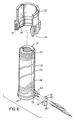
- the inner portion 12 is made with a spiral groove 50 machined in its outer surface 48. While the groove 50 can have various configurations depending upon the thermal requirements of the nozzle 10, in this case, as seen in Figure 6, the pitch of the groove 50 is tighter towards the rear and front ends 14, 16 where more heat is required due to greater heat loss. In this case, the groove 50 is a double groove extending from a U-shaped bend 52 adjacent the front end 16 of the inner portion 12.
- An electrical heating element 54 is bent to fit the U-shaped bend 52 in the spiral groove 50 and then press fitted into the groove 50 as it is wound around the inner portion 12. This provides the heating element 54 with a spiral portion 56 extending in the groove 50 and two remaining terminal portions 58 extending radially outward therefrom.
- the electrical heating element 54 has a resistance wire 60 extending in a refractory powder electrical insulating material 62 such as magnesium oxide powder inside an outer steel casing 64. Initially the heating element 54 has a circular cross-section with a diameter slightly less than the width of the spiral groove 50.
- a terminal locating and sealing key 72 is made of a suitable material such as steel.
- the key 72 is made to fit in a slot 74 in the outer collar portion 32 and has a pin portion 76 extending inwardly therefrom which fits in a matching hole 78 in the head 34 of the inner portion 12.
- the key 72 is made with two holes 80 extending therethrough. The two terminal portions 58 of the heating element 54 are inserted through the two holes 80 and the terminal locating and sealing key 72 is pushed inwardly to the assembled position in which it abuts against the inner portion 12 and the pin portion 76 is received in the hole 78 in the inner portion 12.
- the key 72 is made with two holes 80 and the heating element 54 with two terminal portions 58 which are received through the two holes 80. In other embodiments the key 72 is made with only one hole and the heating element 54 with only one terminal portion which is received through the one hole.
- the outer collar portion 32 is mounted by sliding it over the front end 16 of the inner portion 12 to the assembled position in which the head 34 of the inner portion 12 is received in the seat 36 in the outer collar portion 32.
- the fit of the head 34 in the seat 36 is quite tight to accurately locate the inner portion 12 in the outer collar portion 32.
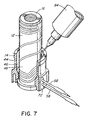
- the outer collar portion 32 is integrally secured in place around the inner portion 12 by applying thermosetting ceramic sealant 82 between them.
- a predetermined quantity of a suitable liquid thermosetting ceramic sealant 82 such as CERAMABOND 668 (trade name of Aremeo) is applied from a pneumatic dispensing tube 84 or syringe into the space 46 between the skirt 44 and the cylindrical outer surface 48 of the inner portion 12.
- the liquid thermosetting ceramic sealant 82 runs down and partially fills the space 46.
- the fit of the terminal locating and sealing key 72 in the slot 74 prevents the liquid sealant leaking out through the slot 74.
- the assembled nozzle is then heated in an oven to a temperature of approximately 200°C to solidify the thermosetting ceramic sealant 82. This integrally secures the inner portion 12 and the outer collar portion 32 together without overheating the heating element 54.
- the terminal locating and sealing key 72 and the solidified sealant 82 prevent leakage of melt between them or around the two terminal portions 58.
- melt distribution manifold 22 In use, electrical power is applied to the heating element 86 in the melt distribution manifold 22 and to the heating elements 54 in the nozzles 10 to heat them to a predetermined operating temperature.
- Pressurized melt is applied from a molding machine (not shown) to the melt passage 20 in the melt distribution manifold 22 according to a predetermined injection cycle.
- the melt flows through the melt bore 18 in the nozzle 10 and through the two-piece nozzle seal 24 to a gate (not shown) in the mold.
- the injection pressure is released and the melt conveying system is decompressed to avoid stringing through the open gates.
- the mold is then opened to eject the molded products. After ejection, the mold is closed and the cycle is repeated continuously with a cycle time dependent upon the size of the cavities and the type of material being molded.
Landscapes
- Engineering & Computer Science (AREA)
- Manufacturing & Machinery (AREA)
- Mechanical Engineering (AREA)
- Injection Moulding Of Plastics Or The Like (AREA)
- Resistance Heating (AREA)
- Manufacture Of Switches (AREA)
- Moulds For Moulding Plastics Or The Like (AREA)
Claims (4)
- Procédé de fabrication d'une buse pour moulage par injection (10) ayant une partie intérieure allongée (12), une partie formant collier extérieur solidaire (32) qui s'ajuste autour de la partie intérieure (12), et un élément chauffant électrique (54), comprenant les étapes consistant à :caractérisé par les étapes consistant à :former la partie intérieure (12) avec une extrémité arrière (14), une extrémité avant (16), un alésage pour masse fondue (18) s'étendant à travers celle-ci à partir de l'extrémité arrière (14), et une surface globalement cylindrique (48) ayant une rainure en spirale (50) s"étendant sur son pourtour,ajuster par pression une partie de l'élément chauffant électrique (54) à l'intérieur de la rainure en spirale (50) pour former une partie en spirale (56) de l'élément chauffant électrique (54) avec au moins une partie formant borne restante (58) de l'élément chauffant électrique (54) qui s'étend vers l'extérieur de celui-ci,glisser la partie formant collier extérieur (32) par-dessus la partie intérieure (12) jusqu'à une position assemblée, cette au moins une partie formant borne (58) de l'élément chauffant (54) s'étendant vers l'extérieur à travers une fente (74) pratiquée dans' la partie formant collier extérieur (32), etfixer la partie formant collier extérieur (32) en position assemblée à proximité immédiate de l'extrémité arrière (14) de la partie intérieure (12) en orientant la partie intérieure (12) de façon à ce que l'extrémité avant (16) soit globalement vers le haut,appliquer un agent d'étanchéité thermodurcissable (82) entre la partie intérieure (12) et la partie formant collier extérieur (32) l'entourant ;réaliser une clavette de positionnement et d'étanchéité de borne (72) qui s'ajuste dans une fente (74) pratiquée dans la partie formant collier extérieur (32), la clavette de positionnement et de scellement de borne (72) ayant des moyens d'engagement s'engageant dans la partie intérieure (12) et positionnant ainsi en rotation la clavette de positionnement et de scellement (72) par rapport à la partie intérieure (12), la clavette de positionnement et de scellement (72) ayant au moins un trou (18) destiné à recevoir dans celui-ci cette au moins une partie formant borne (58) de l'élément chauffant (54),glisser la clavette de positionnement et de scellement de borne (72) par-dessus cette au moins une partie formant borne (58) de l'élément chauffant (54) jusqu'à une position assemblée à laquelle elle est engagée dans la partie intérieure (12) de la buse (10), etglisser la partie formant collier extérieur (32) pour le mettre en position, la clavette de positionnement et de scellement de borne (72) étant reçue dans la fente (74) pratiquée dans la partie formant collier extérieur (32) pour éviter une fuite à travers celle-ci de l'agent d'étanchéité thermodurcissable (82).
- Procédé selon la revendication 1, comprenant la réalisation de la partie intérieure (12) avec une tête (34) au niveau de l'extrémité arrière (14) qui s'étend vers l'extérieur, au-delà de la surface extérieure, la réalisation de la partie formant collier extérieur (32) avec un épaulement (38) s'étendant vers l'intérieur et le glissement de la partie formant collier extérieur (32) par-dessus l'extrémité avant (16) de la partie intérieure (12) jusqu'à la position assemblée à laquelle l'épaulement s'étendant vers l'intérieur (38) de la partie formant collier extérieur (32) vient buter contre la tête (34) de la partie intérieure (12).
- Procédé selon la revendication 1 ou 2, dans lequel la clavette de positionnement et de scellement de borne (72) est réalisée avec les deux trous (80) la traversant et la partie intérieure (12) est réalisée avec la rainure en spirale (50) dans la surface extérieure, celle-ci étant une rainure double s'étendant vers l'arrière à partir d'un coude en forme de U à proximité de l'extrémité avant (16) de sorte que l'élément chauffant (54) présente deux parties formant bornes (58), s'étendant chacune vers l'extérieur à travers l'un respectif des trous (80) pratiqués dans la clavette de positionnement et de scellement (72).
- Procédé selon au moins l'une des revendications précédentes 1 à 3, dans lequel les moyens d'engagement sont une partie formant ergot (72) qui s'étend vers l'intérieur à partir de la clavette de positionnement et de scellement de borne (72) afin de s'ajuster dans un trou correspondant (78) dans la partie intérieure (12) de la buse (10).
Applications Claiming Priority (2)
| Application Number | Priority Date | Filing Date | Title |
|---|---|---|---|
| CA002181964A CA2181964C (fr) | 1996-07-24 | 1996-07-24 | Buse de moulage par injection utilisant une clavette terminale de reperage, avec moyen d'etancheite |
| CA2181964 | 1996-07-24 |
Publications (2)
| Publication Number | Publication Date |
|---|---|
| EP0820847A1 EP0820847A1 (fr) | 1998-01-28 |
| EP0820847B1 true EP0820847B1 (fr) | 2001-11-21 |
Family
ID=4158655
Family Applications (1)
| Application Number | Title | Priority Date | Filing Date |
|---|---|---|---|
| EP97112468A Expired - Lifetime EP0820847B1 (fr) | 1996-07-24 | 1997-07-21 | Procédé de buse de moulage par injection utilisant un élément pour fixer et rendre étanche un fil de contact |
Country Status (5)
| Country | Link |
|---|---|
| US (1) | US5704113A (fr) |
| EP (1) | EP0820847B1 (fr) |
| JP (1) | JPH1086183A (fr) |
| CA (1) | CA2181964C (fr) |
| DE (2) | DE69708405T2 (fr) |
Families Citing this family (23)
| Publication number | Priority date | Publication date | Assignee | Title |
|---|---|---|---|---|
| US6419476B1 (en) * | 1998-08-25 | 2002-07-16 | Joseph P. Ouellette | Thermally insulated runner manifold and injection nozzle construction for plastic molding apparatus |
| CA2250599A1 (fr) * | 1998-10-16 | 2000-04-16 | Jobst Ulrich Gellert | Appareil et methode de fabrication d'une buse de moulage par injection avec col de pastille rapporte |
| US6394784B1 (en) * | 2000-03-08 | 2002-05-28 | Mold-Masters Limited | Compact cartridge hot runner nozzle |
| CA2311829A1 (fr) * | 2000-06-16 | 2001-12-16 | Jonathon Fischer | Buse d'injection a chaud en equilibre thermique |
| CA2475051C (fr) | 2002-02-05 | 2010-05-04 | Mold-Masters Limited | Buse d'injection possedant une partie tete chauffee |
| US6890473B2 (en) * | 2002-09-03 | 2005-05-10 | Mold-Masters Limited | Alignment collar for a nozzle |
| US20050181090A1 (en) * | 2002-12-06 | 2005-08-18 | Mold-Masters Limited | Injection molding nozzle with embedded and removable heaters |
| ITTO20030042A1 (it) * | 2003-01-27 | 2004-07-28 | Piero Enrietti | Dispositivo riscaldatore-diffusore termico per un ugello di |
| US7143496B2 (en) * | 2003-05-08 | 2006-12-05 | Mold-Masters Limited | Hot runner nozzle with removable tip and tip retainer |
| US7381050B2 (en) | 2004-10-20 | 2008-06-03 | Mold-Masters (2007) Limited | Snap on flange for injection molding nozzle |
| US7890896B2 (en) * | 2005-11-18 | 2011-02-15 | Synopsys, Inc. | Method and apparatus for distinguishing combinational designs |
| US7462031B2 (en) * | 2005-11-25 | 2008-12-09 | Mold-Masters (2007) Limited | Injection molding nozzle with recessed terminal |
| ES2682301T3 (es) * | 2007-04-26 | 2018-09-19 | Voss Automotive Gmbh | Conector de tubería para tuberías de fluidos |
| DE202007010865U1 (de) * | 2007-08-03 | 2007-10-11 | Türk & Hillinger GmbH | Elektrische Heizpatrone |
| US9651185B2 (en) | 2008-03-19 | 2017-05-16 | Voss Automotive Gmbh | Line connector for media lines |
| WO2010019213A2 (fr) | 2008-08-11 | 2010-02-18 | Veeco Instruments Inc. | Sources de dépôt sous vide ayant des orifices d'effusion chauffés |
| DE102010032189B4 (de) * | 2010-07-23 | 2024-07-25 | Voss Automotive Gmbh | Verfahren zum Herstellen einer beheizbaren Medienleitung und beheizbare Medienleitung, hergestellt nach dem Verfahren |
| DE102011120357A1 (de) * | 2011-12-07 | 2013-06-13 | Voss Automotive Gmbh | Konfektionierte beheizbare Medienleitung mit einer Medienleitung mit zumindest zwei auf deren Außenseite angeordneten Heizelementen und Verfahren zu ihrer Herstellung |
| US9408256B2 (en) * | 2012-08-07 | 2016-08-02 | Otto Männer Innovation GmbH | Removeable heating device for a heating channel nozzle |
| JP6049398B2 (ja) * | 2012-10-24 | 2016-12-21 | 東京エレクトロン株式会社 | ヒータ装置 |
| DE102018208638A1 (de) * | 2018-05-30 | 2019-12-05 | Ford Global Technologies, Llc | Angusssystem für Spritzgussverfahren |
| FR3106390B1 (fr) * | 2020-01-20 | 2021-12-10 | Hutchinson | Coque chauffante pour raccord trois voies |
| CN115416240B (zh) * | 2022-08-29 | 2026-01-27 | 柳道(青岛)热流道系统有限公司 | 咀尖加热结构及其热咀、热流道系统 |
Family Cites Families (4)
| Publication number | Priority date | Publication date | Assignee | Title |
|---|---|---|---|---|
| US5235737A (en) * | 1991-12-13 | 1993-08-17 | Gellert Jobst U | Method of making an injection molding nozzle with a heating element extending outward between adjacent collar portions |
| US5266023A (en) * | 1992-09-30 | 1993-11-30 | Craig W. Renwick | Injection molding nozzle having an electrical terminal with an insulative connector. |
| CA2137702C (fr) * | 1994-12-07 | 2004-11-02 | Jobst Ulrich Gellert | Buse pour moulage par injection constituee d'un collier monopiece et d'un corps separables; |
| CA2152664C (fr) * | 1995-06-26 | 2008-10-14 | Jobst Ulrich Gellert | Cone de moulage par injection a element chauffant insere a la presse et col d'une seule piece |
-
1996
- 1996-07-24 CA CA002181964A patent/CA2181964C/fr not_active Expired - Fee Related
- 1996-08-19 US US08/699,164 patent/US5704113A/en not_active Expired - Fee Related
-
1997
- 1997-07-17 JP JP9192774A patent/JPH1086183A/ja active Pending
- 1997-07-21 DE DE69708405T patent/DE69708405T2/de not_active Expired - Fee Related
- 1997-07-21 EP EP97112468A patent/EP0820847B1/fr not_active Expired - Lifetime
- 1997-07-21 DE DE19731214A patent/DE19731214A1/de not_active Withdrawn
Also Published As
| Publication number | Publication date |
|---|---|
| CA2181964C (fr) | 2007-02-20 |
| US5704113A (en) | 1998-01-06 |
| DE19731214A1 (de) | 1998-01-29 |
| EP0820847A1 (fr) | 1998-01-28 |
| DE69708405T2 (de) | 2002-05-29 |
| DE69708405D1 (de) | 2002-01-03 |
| CA2181964A1 (fr) | 1998-01-25 |
| JPH1086183A (ja) | 1998-04-07 |
Similar Documents
| Publication | Publication Date | Title |
|---|---|---|
| US5704113A (en) | Injection molding nozzle method using a terminal locating and sealing key | |
| EP0750974B1 (fr) | Buse de moulage par injection avec élément de chauffage enfoncé et partie de collerette intégrée | |
| CA1238161A (fr) | Fabrication de buses a fenetres configurables au choix pour le moulage par injection | |
| US4911636A (en) | Injection molding nozzle having nose portion with heating element encircling the bore | |
| US4450999A (en) | Injection molding hot tip seal | |
| CA1265909A (fr) | Garniture sur guichet chauffe de moulage par injection, et methode connexe | |
| US6625873B1 (en) | Method of making an injection molding nozzle with tip insert | |
| CA2187497C (fr) | Bague-guide de scellement pour buse de moulage par injection | |
| EP0755766A1 (fr) | Buse de moulage par injection avec des palettes radiales | |
| US4424622A (en) | Method of making integral corrosion resistant manifold | |
| EP0374549A2 (fr) | Dispositif de moulage par injection avec des inserts refroidis par un fluide | |
| EP0681899A2 (fr) | Procédé de distributeur de moulage par injection avec élément de chauffage disposé entre des plaques | |
| EP0380748B1 (fr) | Système d'injection pour moule à étages avec buse à carotte | |
| US4836766A (en) | Injection molding valve gating one of two nozzles in tandem | |
| CA1149569A (fr) | Systeme de moulage a injection laterale | |
| CA2059960C (fr) | Aiguille d'injection a tube a thermocouple et element chauffants coaxiaux | |
| CA2057439C (fr) | Methode de fabrication d'une sonde pour le moulage par injection | |
| US4777348A (en) | Injection molding probe with insulation and locating hoop portion | |
| CA2037186C (fr) | Sonde comprennant un logement longitudinal pour couple thermoelectrique et un element chauffant excentrique, dans un systeme de moulage par injection | |
| US4854851A (en) | Injection molding system with insertable insulating ring | |
| US5238391A (en) | Injection molding probe with coaxial thermocouple tube and heating element | |
| CA1274368A (fr) | Systeme de moulage par injection, avec bague isolante rapportee | |
| CA2032728A1 (fr) | Sonde pour moulage par injection permettant une diffusion variable de la chaleur | |
| CA2250598A1 (fr) | Appareil pour localiser et sceller une buse de moulage par injection | |
| EP0299333A1 (fr) | Elément chauffant pour des machines d'injection avec portion annulaire d'isolation et de fixation |
Legal Events
| Date | Code | Title | Description |
|---|---|---|---|
| PUAI | Public reference made under article 153(3) epc to a published international application that has entered the european phase |
Free format text: ORIGINAL CODE: 0009012 |
|
| AK | Designated contracting states |
Kind code of ref document: A1 Designated state(s): AT BE CH DE DK ES FI FR GB GR IE IT LI LU MC NL PT SE |
|
| 17P | Request for examination filed |
Effective date: 19980616 |
|
| RBV | Designated contracting states (corrected) |
Designated state(s): CH DE ES FR GB IT LI LU NL PT |
|
| 17Q | First examination report despatched |
Effective date: 19991223 |
|
| GRAG | Despatch of communication of intention to grant |
Free format text: ORIGINAL CODE: EPIDOS AGRA |
|
| GRAG | Despatch of communication of intention to grant |
Free format text: ORIGINAL CODE: EPIDOS AGRA |
|
| GRAH | Despatch of communication of intention to grant a patent |
Free format text: ORIGINAL CODE: EPIDOS IGRA |
|
| GRAH | Despatch of communication of intention to grant a patent |
Free format text: ORIGINAL CODE: EPIDOS IGRA |
|
| GRAA | (expected) grant |
Free format text: ORIGINAL CODE: 0009210 |
|
| AK | Designated contracting states |
Kind code of ref document: B1 Designated state(s): CH DE ES FR GB IT LI LU NL PT |
|
| PG25 | Lapsed in a contracting state [announced via postgrant information from national office to epo] |
Ref country code: IT Free format text: LAPSE BECAUSE OF FAILURE TO SUBMIT A TRANSLATION OF THE DESCRIPTION OR TO PAY THE FEE WITHIN THE PRESCRIBED TIME-LIMIT;WARNING: LAPSES OF ITALIAN PATENTS WITH EFFECTIVE DATE BEFORE 2007 MAY HAVE OCCURRED AT ANY TIME BEFORE 2007. THE CORRECT EFFECTIVE DATE MAY BE DIFFERENT FROM THE ONE RECORDED. Effective date: 20011121 Ref country code: FR Free format text: LAPSE BECAUSE OF FAILURE TO SUBMIT A TRANSLATION OF THE DESCRIPTION OR TO PAY THE FEE WITHIN THE PRESCRIBED TIME-LIMIT Effective date: 20011121 |
|
| REG | Reference to a national code |
Ref country code: CH Ref legal event code: NV Representative=s name: PATENTANWALTSBUERO JEAN HUNZIKER Ref country code: CH Ref legal event code: EP |
|
| REG | Reference to a national code |
Ref country code: GB Ref legal event code: IF02 |
|
| REF | Corresponds to: |
Ref document number: 69708405 Country of ref document: DE Date of ref document: 20020103 |
|
| PG25 | Lapsed in a contracting state [announced via postgrant information from national office to epo] |
Ref country code: PT Free format text: LAPSE BECAUSE OF FAILURE TO SUBMIT A TRANSLATION OF THE DESCRIPTION OR TO PAY THE FEE WITHIN THE PRESCRIBED TIME-LIMIT Effective date: 20020221 |
|
| PG25 | Lapsed in a contracting state [announced via postgrant information from national office to epo] |
Ref country code: ES Free format text: LAPSE BECAUSE OF FAILURE TO SUBMIT A TRANSLATION OF THE DESCRIPTION OR TO PAY THE FEE WITHIN THE PRESCRIBED TIME-LIMIT Effective date: 20020530 |
|
| PG25 | Lapsed in a contracting state [announced via postgrant information from national office to epo] |
Ref country code: GB Free format text: LAPSE BECAUSE OF NON-PAYMENT OF DUE FEES Effective date: 20020721 |
|
| PLBE | No opposition filed within time limit |
Free format text: ORIGINAL CODE: 0009261 |
|
| STAA | Information on the status of an ep patent application or granted ep patent |
Free format text: STATUS: NO OPPOSITION FILED WITHIN TIME LIMIT |
|
| EN | Fr: translation not filed | ||
| 26N | No opposition filed | ||
| GBPC | Gb: european patent ceased through non-payment of renewal fee |
Effective date: 20020721 |
|
| REG | Reference to a national code |
Ref country code: CH Ref legal event code: PUE Owner name: MOLD-MASTERS (2007) LIMITED Free format text: MOLD-MASTERS LIMITED#233 ARMSTRONG AVENUE#GEORGETOWN ONTARIO L7G 4X5 (CA) -TRANSFER TO- MOLD-MASTERS (2007) LIMITED#233 ARMSTRONG AVE.#GEORGETOWN, ONTARIO L7G 4X5 (CA) |
|
| NLS | Nl: assignments of ep-patents |
Owner name: MOLD-MASTERS (2007) LIMITED Effective date: 20080530 |
|
| PGFP | Annual fee paid to national office [announced via postgrant information from national office to epo] |
Ref country code: LU Payment date: 20080710 Year of fee payment: 12 Ref country code: DE Payment date: 20080730 Year of fee payment: 12 Ref country code: CH Payment date: 20080708 Year of fee payment: 12 |
|
| PGFP | Annual fee paid to national office [announced via postgrant information from national office to epo] |
Ref country code: NL Payment date: 20080711 Year of fee payment: 12 |
|
| REG | Reference to a national code |
Ref country code: CH Ref legal event code: PL |
|
| NLV4 | Nl: lapsed or anulled due to non-payment of the annual fee |
Effective date: 20100201 |
|
| PG25 | Lapsed in a contracting state [announced via postgrant information from national office to epo] |
Ref country code: LI Free format text: LAPSE BECAUSE OF NON-PAYMENT OF DUE FEES Effective date: 20090731 Ref country code: CH Free format text: LAPSE BECAUSE OF NON-PAYMENT OF DUE FEES Effective date: 20090731 |
|
| PG25 | Lapsed in a contracting state [announced via postgrant information from national office to epo] |
Ref country code: DE Free format text: LAPSE BECAUSE OF NON-PAYMENT OF DUE FEES Effective date: 20100202 |
|
| PG25 | Lapsed in a contracting state [announced via postgrant information from national office to epo] |
Ref country code: LU Free format text: LAPSE BECAUSE OF NON-PAYMENT OF DUE FEES Effective date: 20090721 |
|
| PG25 | Lapsed in a contracting state [announced via postgrant information from national office to epo] |
Ref country code: NL Free format text: LAPSE BECAUSE OF NON-PAYMENT OF DUE FEES Effective date: 20100201 |