EP0820866A2 - Dispositif d'encrage pour une machine à imprimer rotative - Google Patents
Dispositif d'encrage pour une machine à imprimer rotative Download PDFInfo
- Publication number
- EP0820866A2 EP0820866A2 EP97112318A EP97112318A EP0820866A2 EP 0820866 A2 EP0820866 A2 EP 0820866A2 EP 97112318 A EP97112318 A EP 97112318A EP 97112318 A EP97112318 A EP 97112318A EP 0820866 A2 EP0820866 A2 EP 0820866A2
- Authority
- EP
- European Patent Office
- Prior art keywords
- roller
- inking unit
- unit according
- ink
- holder
- Prior art date
- Legal status (The legal status is an assumption and is not a legal conclusion. Google has not performed a legal analysis and makes no representation as to the accuracy of the status listed.)
- Granted
Links
Images





Classifications
-
- B—PERFORMING OPERATIONS; TRANSPORTING
- B41—PRINTING; LINING MACHINES; TYPEWRITERS; STAMPS
- B41F—PRINTING MACHINES OR PRESSES
- B41F31/00—Inking arrangements or devices
- B41F31/02—Ducts, containers, supply or metering devices
- B41F31/04—Ducts, containers, supply or metering devices with duct-blades or like metering devices
-
- B—PERFORMING OPERATIONS; TRANSPORTING
- B41—PRINTING; LINING MACHINES; TYPEWRITERS; STAMPS
- B41F—PRINTING MACHINES OR PRESSES
- B41F35/00—Cleaning arrangements or devices
- B41F35/04—Cleaning arrangements or devices for inking rollers
Definitions
- the invention relates to an inking unit for rotary printing presses according to the Preamble of claim 1.
- an inking unit is rotatable with one in the frame stored roller in the form of a color ductor and one of these swivel-mounted paint container in the form of a paint box known.
- the invention has for its object an inking unit for rotary printing presses according to the preamble of claim 1 to create the both a largely color residue-avoiding, user-friendly Color emptying of the paint container as well as a thorough cleaning good accessibility of the latter and the roller.
- the combination of the swiveling movements of the paint container and the die Roller bearing bracket allows favorable conditions for both the Color emptying of the paint container as well as the cleaning of the latter as well as the roller, including washing.
- the roller and the ink tank together into a roller that drains off the ink releasing position can be pivoted so that the following Swiveling the ink container away from the roller prevents ink from escaping becomes.
- the color emptying of a paint container or the Removal of an additional stake favors, and for a very good one Accessibility when washing is from the already swiveled roller the paint container can also be swung out.
- the solution according to the invention also allows an interruption of the Contact of the still operational roller and ink duct Establishment of a downstream transfer roller. It is the roller can be driven as required in any swivel position.
- the one working with a paint container in the form of a chambered doctor blade Roller can be equipped with recesses for ink absorption both as anilox roller for a short inking unit as well as a uniform structured Form roller for example for fund printing or as uneven structured form roller can be designed for general printing.
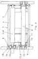
- Fig. 1 shows in connection with Fig. 6 a rotatable in a holder 1 stored, drivable roller I in the form of an ink fountain roller 2, to the one Paint container II is pivoted in the form of a paint box 3.
- Paint container II is pivoted in the form of a paint box 3.
- the one lying on the inside of the frame Axis 8 has an axially matching bore 10 in gesture 9 aligned fitting bore 11, in which in the fitting bore 10 in gesture 9 engaging dowel pin 12 sits.
- the axis 8 is in each case on the end face screwed to the frame 9 (Fig. 6).
- a motor 13 is located on the side of the lever 6, coaxial with the ink fountain roller 2 flanged to the ink fountain roller 2 via a fixed coupling 14 connected is.
- the gesture 9 is for the motor 13 with the pivoting the bracket 1 enabling recess 15 equipped.
- the ink fountain 3 is attached to the ink fountain roller 2 swiveled position lockable against the bracket 1.
- To engages in the housing of the ink fountain axially displaceable locking bolt 16 into a bore 17 of the holder 1 that is aligned with this a.
- the holder 1 In the operating position, the holder 1 lies against an adjustable stop 18 the contact of the ink fountain roller 2 to a downstream transfer roller 19 limiting.
- bracket 1 and the locked paint box 3 together by means of a pressure medium operated, acting on the bracket 1 and on Gestured articulated cylinder 20 is pivoted, this is done separately for unlocked ink fountain 3 by hand with the help one attached to this handle 21, the pivoting movement of the Color box 3 favorably by a stop, not shown or a lock relative to the bracket can be limited.
- the color box 3 with a exchangeable ink fountain insert 22.
- Fig. 6 are four ink boxes 3, each of a quarter-wide design arranged separately next to each other. These are alternative interchangeable with a full or one or two half-width ink boxes.
- the storage 24 for the Ink fountain 3 in several parts, which can be screwed together radially on axis 8 Bearing shells 25; 26 are executed. This is also a quick one Exchange of different width ink boxes possible.
- FIG. 3 shows, compared to FIG. 2, one after the locking bolt 16 has been released from the bore 17 of the holder 1 from the ink fountain roller 3 additionally pivoted paint box 3, which the entire facility for the Cleaning is optimally accessible.
- Fig. 4 shows the holder 1 with the ink fountain roller 2 in contact with Transfer roller 19 analog to FIG. 1 and the ink fountain 3 analog to FIG. 3 in which a cleaning, pivoted away from the ink fountain roller 3 Position.
- Fig. 5 shows a parked by the transfer roller 19 and thus in Contact of the ink fountain roller 2 to the transfer roller 19 interrupted, otherwise, however, operational facility.
- FIGS. 7 and 8 show a modified version with respect to FIGS. 1 and 6 Device that the bracket 1 'by means of one of the two levers 6', 7 ' connecting, mounted on the axis 8, the ink fountain 3 'pivotable bearing tube 29 is effectively stiffened as a crossbar.
- the locking bolt 16 'of the ink fountain 3' engages in this version in the tube 29 arranged bore 17 '.
- the ink fountain 3 'in FIG. 7 is on the one hand on one attached to the tube 29, the storage 24 'of the ink fountain 3' in one a recess 30 permitting a pivoting movement radially penetrating Lever 31 and on the other hand on the ink fountain 3 'articulated cylinder 32 swiveling.
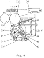
- FIG. 9 shows an axis parallel to the mounting of the holder 1 ′′ offset in this stored color box 3 ''.
- the tube 29 'and on the ink fountain 3 ′′ mutually overlapping bearing levers 33, 34 attached, each parallel to the axis 8 'of the bracket 1' ' Bearing bolts 35 are penetrated.
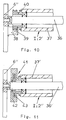
- FIG. 10 shows a drive variant for an axle 36 that is fixed to the frame and equipped with a roller jacket 37 rotatably mounted on the latter Ink fountain roller 2 ', such as one laterally attached to the lever 6' ' Motor 38 by means of a worm 39 on the roller jacket 37 coaxially attached worm wheel 40 drives.
- an ink fountain roller 2 '' of the same design as in Fig. 10 drives a disc rotor motor 41, whose rotor 42 coaxially on the roll shell 37 'is fixed and stator 43 is seated on the axis 36'.
- the drive for the ink fountain roller 2 is not shown; 2 '; 2 '' can also be designed such that on the axis 8 or the tube 29; 29 'coaxial to the pivot axis of the holder 1; 1'; 1 '' an arbitrarily drivable drive wheel is rotatably mounted, which via a drive with the ink fountain roller 2; 2 '; 2 '' communicates.
- the drive wheel can be designed as a toothed disc, which is connected to the ink fountain roller 2 or its roller jacket 37; 37 'drives firmly connected, coaxial toothed disc. It is also conceivable to replace the toothed disks by spur gears, which have at least one in the holder 1; 1'; 1 '' mounted spur gear mesh with each other.
- FIGS. 1 to 8 show a chamber doctor blade 44 in a schematic representation as ink container II '; 44 'and as roller I' an anilox roller 45; 45 ', with the doctor blade 44 in FIG. 12 analogous to the ink fountain 3''in FIG. 9 to the pivot axis of the holder 46 carrying the anilox roller 45 offset axially parallel in the holder 46 and in FIG. 13 the chamber doctor blade 44' analog to the ink fountain 3; 3 'in FIGS. 1 to 8 is pivotally mounted coaxially to the pivot axis of the holder 46' carrying the anilox roller 45 '.
- the anilox roller 45; 45 ' is particularly suitable for the short inking units working with chambered doctor blade and anilox roller, the anilox roller 45; 45 'a transfer roller 47'; 47 of the respective short inking system.
- the anilox roller 45; 45' to provide a form roller equipped with recesses for ink absorption, which dyes a transfer roller in the indirect printing process.
- the form roller can be designed both uniformly structured, for example for fund printing, or unevenly structured for general printing.
- the specially for one from color box 3; 3 '; 3 '' and ink fountain roller 2; 2 '; 2 '' existing facility described and illustrated solution variants 1 to 11 are the bracket, storage and drive Ink fountain roller and storage of the ink fountain also on the chamber doctor blade 44; 44 'and the anilox roller 45; 45 'according to FIGS. 11 and 12 can be transferred.
Landscapes
- Inking, Control Or Cleaning Of Printing Machines (AREA)
Applications Claiming Priority (2)
| Application Number | Priority Date | Filing Date | Title |
|---|---|---|---|
| DE19629811 | 1996-07-24 | ||
| DE19629811A DE19629811A1 (de) | 1996-07-24 | 1996-07-24 | Farbwerk für Rotationsdruckmaschinen |
Publications (3)
| Publication Number | Publication Date |
|---|---|
| EP0820866A2 true EP0820866A2 (fr) | 1998-01-28 |
| EP0820866A3 EP0820866A3 (fr) | 1998-07-15 |
| EP0820866B1 EP0820866B1 (fr) | 2002-04-10 |
Family
ID=7800668
Family Applications (1)
| Application Number | Title | Priority Date | Filing Date |
|---|---|---|---|
| EP97112318A Expired - Lifetime EP0820866B1 (fr) | 1996-07-24 | 1997-07-18 | Dispositif d'encrage pour une machine à imprimer rotative |
Country Status (3)
| Country | Link |
|---|---|
| US (1) | US5848570A (fr) |
| EP (1) | EP0820866B1 (fr) |
| DE (2) | DE19629811A1 (fr) |
Cited By (1)
| Publication number | Priority date | Publication date | Assignee | Title |
|---|---|---|---|---|
| US8783175B2 (en) | 2011-07-06 | 2014-07-22 | Heidelberger Druckmaschinen Ag | Method for operating an anilox printing unit and printing press with an anilox printing unit |
Families Citing this family (8)
| Publication number | Priority date | Publication date | Assignee | Title |
|---|---|---|---|---|
| DE19651816C2 (de) * | 1996-12-13 | 1999-10-28 | Roland Man Druckmasch | Antriebsvorrichtung für eine Walze eines Farbbehälters |
| DE10039279A1 (de) * | 1999-09-09 | 2001-03-15 | Heidelberger Druckmasch Ag | Walze für Druckmaschinen |
| JP4540183B2 (ja) * | 2000-05-24 | 2010-09-08 | 株式会社小森コーポレーション | 輪転印刷機のインキ装置 |
| DE10243732B4 (de) | 2001-10-19 | 2018-08-09 | Heidelberger Druckmaschinen Ag | Antriebssystem für einen Zylinder einer Druckmaschine |
| DE20118941U1 (de) | 2001-11-20 | 2002-02-14 | MAN Roland Druckmaschinen AG, 63075 Offenbach | Farbwerk für eine Rotationsdruckmaschine |
| CN1325257C (zh) * | 2004-01-08 | 2007-07-11 | 寿原株式会社 | 墨斗 |
| JP2005297201A (ja) * | 2004-04-06 | 2005-10-27 | Taiyo Kikai Seisakusho:Kk | フレキソ印刷機用インク供給ユニット |
| DE102006013636B4 (de) * | 2006-03-22 | 2012-02-09 | Siemens Ag | Druckmaschine bzw. elektrische Maschine für eine Druckmaschine |
Family Cites Families (13)
| Publication number | Priority date | Publication date | Assignee | Title |
|---|---|---|---|---|
| US2514556A (en) * | 1947-03-11 | 1950-07-11 | Miehle Printing Press & Mfg | Ink fountain structure |
| US3921525A (en) * | 1973-10-30 | 1975-11-25 | American Bank Note Co | Adjustable and retractable ink supply mechanism for printing press |
| DE2629331C3 (de) * | 1976-06-30 | 1979-03-08 | Roland Offsetmaschinenfabrik Faber & Schleicher Ag, 6050 Offenbach | Farbdosiereinrichtung an Druckmaschinen |
| US4155303A (en) * | 1978-02-17 | 1979-05-22 | Johnston Willis K | Detachable ink fountain |
| DE2951649C2 (de) * | 1979-12-21 | 1982-11-18 | M.A.N.- Roland Druckmaschinen AG, 6050 Offenbach | Farbkasten von Druckmaschinen |
| DD207521A1 (de) * | 1982-06-03 | 1984-03-07 | Hans Johne | Lagerung von farbkaesten |
| FR2527987B1 (fr) * | 1982-06-04 | 1986-06-20 | Creusot Loire | Dispositif d'encrage a lame basse a cuvettes d'encrier amovibles |
| DE3400831C2 (de) * | 1984-01-12 | 1986-03-06 | M.A.N.- Roland Druckmaschinen AG, 6050 Offenbach | Farbkasten für eine Druckmaschine |
| US4617865A (en) * | 1985-08-07 | 1986-10-21 | Ryco Graphic Manufacturing, Inc. | Liquid coater for a printing press with moveable inking roller and tray |
| DE8912194U1 (de) * | 1989-10-13 | 1989-11-23 | MAN Roland Druckmaschinen AG, 6050 Offenbach | Farbwerk |
| US5081928A (en) * | 1990-07-23 | 1992-01-21 | Ward Holding Company, Inc. | Multiple ink roll system for flexographic printing stations |
| DE4224795C2 (de) * | 1991-08-08 | 1994-08-25 | Siemens Ag | Verfahren und Vorrichtung zur Erzeugung eines stabilen Regelverhaltens einer Einspeiseschaltung |
| DE4224775A1 (de) * | 1992-07-27 | 1992-12-10 | Koenig & Bauer Ag | Verfahren, einrichtung und rakel zum entleeren von farbkaesten fuer rotationsdruckmaschinen |
-
1996
- 1996-07-24 DE DE19629811A patent/DE19629811A1/de not_active Withdrawn
-
1997
- 1997-07-18 DE DE59706938T patent/DE59706938D1/de not_active Expired - Lifetime
- 1997-07-18 EP EP97112318A patent/EP0820866B1/fr not_active Expired - Lifetime
- 1997-07-24 US US08/899,929 patent/US5848570A/en not_active Expired - Lifetime
Cited By (1)
| Publication number | Priority date | Publication date | Assignee | Title |
|---|---|---|---|---|
| US8783175B2 (en) | 2011-07-06 | 2014-07-22 | Heidelberger Druckmaschinen Ag | Method for operating an anilox printing unit and printing press with an anilox printing unit |
Also Published As
| Publication number | Publication date |
|---|---|
| EP0820866A3 (fr) | 1998-07-15 |
| EP0820866B1 (fr) | 2002-04-10 |
| DE59706938D1 (de) | 2002-05-16 |
| US5848570A (en) | 1998-12-15 |
| DE19629811A1 (de) | 1998-01-29 |
Similar Documents
| Publication | Publication Date | Title |
|---|---|---|
| EP0980312B1 (fr) | Palier pour cylindre de rotative | |
| DE19740129A1 (de) | Rotationsdruckmaschine mit stirnseitig freilegbaren Zylindern | |
| DE19624440A1 (de) | Einrichtung zum Füllen von Vertiefungen eines Zylinders, Rakeleinrichtungen hierfür sowie Verfahren zu deren Wechsel | |
| DE3102139C2 (de) | Farbwerk für eine Rotationsdruckmaschine | |
| DE2948715C2 (de) | Streuwagen für auszustreuendes Gut, insbesondere Dünger | |
| EP0492102B1 (fr) | Palier pour cylindre de groupe d'impression | |
| EP0820866B1 (fr) | Dispositif d'encrage pour une machine à imprimer rotative | |
| EP0663293B1 (fr) | Dispositif pour encrer un rouleau tramé | |
| DE4001736A1 (de) | Lagerhalterung fuer auf wellenzapfen aufgesetzte lager | |
| DE10315191B4 (de) | Druckmaschine mit einem Walzenmagazin | |
| DE102008016598B4 (de) | Druckwerk/Lackierwerk einer Druckmaschine mit einer Vorrichtung zum Austausch von Rasterwalzen | |
| EP0345253A1 (fr) | Procede pour le demontage de la vis sur le cylindre de vis d'une presse d'injection, et configuration appropriee de ladite presse. | |
| EP0453772A1 (fr) | Dispositif d'encrage à racle | |
| DE3932232A1 (de) | Rakelvorrichtung | |
| DE10209536B4 (de) | Druckmaschine, vorzugsweise Flexodruckmaschine | |
| EP1090756B1 (fr) | Chambre à râcles | |
| EP1671790B1 (fr) | Module interchangeable pour machine d'impression | |
| EP2718104B1 (fr) | Système d'impression d'une machine de rotogravure comprenant un bac à encre pivotant et procédé pour encrer et nettoyer un cylindre de rotogravure | |
| DE4328834B4 (de) | Wascheinrichtung im Farbwerk von Druckmaschinen | |
| EP2114681B1 (fr) | Groupe d'impression d'une presse rotative et procédé de lavage d'un groupe de mouillage d'un groupe d'impression | |
| EP1552925B1 (fr) | Support pour une cartouche à encre | |
| DE19629810A1 (de) | Farbwerk für Rotationsdruckmaschinen | |
| DE20118941U1 (de) | Farbwerk für eine Rotationsdruckmaschine | |
| EP2079588A1 (fr) | Ensemble de palier de support pour un rouleau encreur ou de contre-pression | |
| DE102007027385B4 (de) | Farbkammer für ein Farbwerk einer Rotationsdruckmaschine und Verfahren zur Herstellung einer solchen Farbkammer |
Legal Events
| Date | Code | Title | Description |
|---|---|---|---|
| PUAI | Public reference made under article 153(3) epc to a published international application that has entered the european phase |
Free format text: ORIGINAL CODE: 0009012 |
|
| AK | Designated contracting states |
Kind code of ref document: A2 Designated state(s): CH DE FR GB LI SE |
|
| AX | Request for extension of the european patent |
Free format text: AL;LT;LV;RO;SI |
|
| PUAL | Search report despatched |
Free format text: ORIGINAL CODE: 0009013 |
|
| AK | Designated contracting states |
Kind code of ref document: A3 Designated state(s): AT BE CH DE DK ES FI FR GB GR IE IT LI LU MC NL PT SE |
|
| AX | Request for extension of the european patent |
Free format text: AL;LT;LV;RO;SI |
|
| 17P | Request for examination filed |
Effective date: 19981203 |
|
| AKX | Designation fees paid |
Free format text: CH DE FR GB LI SE |
|
| RBV | Designated contracting states (corrected) |
Designated state(s): CH DE FR GB LI SE |
|
| 17Q | First examination report despatched |
Effective date: 19990719 |
|
| GRAG | Despatch of communication of intention to grant |
Free format text: ORIGINAL CODE: EPIDOS AGRA |
|
| GRAG | Despatch of communication of intention to grant |
Free format text: ORIGINAL CODE: EPIDOS AGRA |
|
| GRAH | Despatch of communication of intention to grant a patent |
Free format text: ORIGINAL CODE: EPIDOS IGRA |
|
| GRAH | Despatch of communication of intention to grant a patent |
Free format text: ORIGINAL CODE: EPIDOS IGRA |
|
| REG | Reference to a national code |
Ref country code: GB Ref legal event code: IF02 |
|
| GRAA | (expected) grant |
Free format text: ORIGINAL CODE: 0009210 |
|
| AK | Designated contracting states |
Kind code of ref document: B1 Designated state(s): CH DE FR GB LI SE |
|
| REG | Reference to a national code |
Ref country code: CH Ref legal event code: EP |
|
| REG | Reference to a national code |
Ref country code: CH Ref legal event code: NV Representative=s name: E. BLUM & CO. PATENTANWAELTE |
|
| REF | Corresponds to: |
Ref document number: 59706938 Country of ref document: DE Date of ref document: 20020516 |
|
| GBT | Gb: translation of ep patent filed (gb section 77(6)(a)/1977) |
Effective date: 20020710 |
|
| ET | Fr: translation filed | ||
| PLBE | No opposition filed within time limit |
Free format text: ORIGINAL CODE: 0009261 |
|
| STAA | Information on the status of an ep patent application or granted ep patent |
Free format text: STATUS: NO OPPOSITION FILED WITHIN TIME LIMIT |
|
| 26N | No opposition filed |
Effective date: 20030113 |
|
| REG | Reference to a national code |
Ref country code: CH Ref legal event code: PFA Owner name: MAN ROLAND DRUCKMASCHINEN AG Free format text: MAN ROLAND DRUCKMASCHINEN AG#POSTFACH 10 12 64#63012 OFFENBACH (DE) -TRANSFER TO- MAN ROLAND DRUCKMASCHINEN AG#POSTFACH 10 12 64#63012 OFFENBACH (DE) |
|
| REG | Reference to a national code |
Ref country code: CH Ref legal event code: PFA Owner name: MANROLAND AG Free format text: MAN ROLAND DRUCKMASCHINEN AG#POSTFACH 10 12 64#63012 OFFENBACH (DE) -TRANSFER TO- MANROLAND AG#MUEHLHEIMER STRA?E 341#63075 OFFENBACH (DE) |
|
| REG | Reference to a national code |
Ref country code: FR Ref legal event code: CD |
|
| PGFP | Annual fee paid to national office [announced via postgrant information from national office to epo] |
Ref country code: CH Payment date: 20110725 Year of fee payment: 15 Ref country code: FR Payment date: 20110729 Year of fee payment: 15 |
|
| PGFP | Annual fee paid to national office [announced via postgrant information from national office to epo] |
Ref country code: DE Payment date: 20110722 Year of fee payment: 15 Ref country code: SE Payment date: 20110722 Year of fee payment: 15 Ref country code: GB Payment date: 20110721 Year of fee payment: 15 |
|
| REG | Reference to a national code |
Ref country code: DE Ref legal event code: R081 Ref document number: 59706938 Country of ref document: DE Owner name: MANROLAND WEB SYSTEMS GMBH, DE Free format text: FORMER OWNER: MANROLAND AG, 63075 OFFENBACH, DE Effective date: 20120626 |
|
| REG | Reference to a national code |
Ref country code: CH Ref legal event code: PL |
|
| REG | Reference to a national code |
Ref country code: SE Ref legal event code: EUG |
|
| GBPC | Gb: european patent ceased through non-payment of renewal fee |
Effective date: 20120718 |
|
| REG | Reference to a national code |
Ref country code: FR Ref legal event code: ST Effective date: 20130329 |
|
| PG25 | Lapsed in a contracting state [announced via postgrant information from national office to epo] |
Ref country code: SE Free format text: LAPSE BECAUSE OF NON-PAYMENT OF DUE FEES Effective date: 20120719 Ref country code: GB Free format text: LAPSE BECAUSE OF NON-PAYMENT OF DUE FEES Effective date: 20120718 Ref country code: CH Free format text: LAPSE BECAUSE OF NON-PAYMENT OF DUE FEES Effective date: 20120731 Ref country code: FR Free format text: LAPSE BECAUSE OF NON-PAYMENT OF DUE FEES Effective date: 20120731 Ref country code: LI Free format text: LAPSE BECAUSE OF NON-PAYMENT OF DUE FEES Effective date: 20120731 Ref country code: DE Free format text: LAPSE BECAUSE OF NON-PAYMENT OF DUE FEES Effective date: 20130201 |
|
| REG | Reference to a national code |
Ref country code: DE Ref legal event code: R119 Ref document number: 59706938 Country of ref document: DE Effective date: 20130201 |