EP0820910A2 - Pyrotechnische Linearantriebseinrichtung für einen Gurtstraffer - Google Patents
Pyrotechnische Linearantriebseinrichtung für einen Gurtstraffer Download PDFInfo
- Publication number
- EP0820910A2 EP0820910A2 EP97111648A EP97111648A EP0820910A2 EP 0820910 A2 EP0820910 A2 EP 0820910A2 EP 97111648 A EP97111648 A EP 97111648A EP 97111648 A EP97111648 A EP 97111648A EP 0820910 A2 EP0820910 A2 EP 0820910A2
- Authority
- EP
- European Patent Office
- Prior art keywords
- drive device
- linear drive
- gas generator
- propellant
- vehicle
- Prior art date
- Legal status (The legal status is an assumption and is not a legal conclusion. Google has not performed a legal analysis and makes no representation as to the accuracy of the status listed.)
- Withdrawn
Links
Images



Classifications
-
- B—PERFORMING OPERATIONS; TRANSPORTING
- B60—VEHICLES IN GENERAL
- B60R—VEHICLES, VEHICLE FITTINGS, OR VEHICLE PARTS, NOT OTHERWISE PROVIDED FOR
- B60R22/00—Safety belts or body harnesses in vehicles
- B60R22/34—Belt retractors, e.g. reels
- B60R22/46—Reels with means to tension the belt in an emergency by forced winding up
- B60R22/4628—Reels with means to tension the belt in an emergency by forced winding up characterised by fluid actuators, e.g. pyrotechnic gas generators
- B60R22/4633—Linear actuators, e.g. comprising a piston moving along reel axis and rotating along its own axis
-
- F—MECHANICAL ENGINEERING; LIGHTING; HEATING; WEAPONS; BLASTING
- F42—AMMUNITION; BLASTING
- F42B—EXPLOSIVE CHARGES, e.g. FOR BLASTING, FIREWORKS, AMMUNITION
- F42B3/00—Blasting cartridges, i.e. case and explosive
- F42B3/04—Blasting cartridges, i.e. case and explosive for producing gas under pressure
-
- B—PERFORMING OPERATIONS; TRANSPORTING
- B60—VEHICLES IN GENERAL
- B60R—VEHICLES, VEHICLE FITTINGS, OR VEHICLE PARTS, NOT OTHERWISE PROVIDED FOR
- B60R22/00—Safety belts or body harnesses in vehicles
- B60R22/34—Belt retractors, e.g. reels
- B60R22/46—Reels with means to tension the belt in an emergency by forced winding up
- B60R22/4628—Reels with means to tension the belt in an emergency by forced winding up characterised by fluid actuators, e.g. pyrotechnic gas generators
- B60R2022/4657—Reels with means to tension the belt in an emergency by forced winding up characterised by fluid actuators, e.g. pyrotechnic gas generators comprising a plurality of charges
-
- B—PERFORMING OPERATIONS; TRANSPORTING
- B60—VEHICLES IN GENERAL
- B60R—VEHICLES, VEHICLE FITTINGS, OR VEHICLE PARTS, NOT OTHERWISE PROVIDED FOR
- B60R22/00—Safety belts or body harnesses in vehicles
- B60R22/34—Belt retractors, e.g. reels
- B60R22/46—Reels with means to tension the belt in an emergency by forced winding up
- B60R2022/4685—Reels with means to tension the belt in an emergency by forced winding up with means to adjust or regulate the tensioning force in relation to external parameters
Definitions
- the invention relates to a pyrotechnic linear drive device for a belt tensioner, with a piston-cylinder unit, a gas generator for driving the piston and an ignition unit for triggering a propellant charge of the gas generator.
- the invention provides a pyrotechnic linear drive device created for a belt tensioner, the drive energy in several stages is provided, depending on parameters such as height, body weight, sitting position or Impact intensity to ensure an adjusted, optimal belt tensioning.
- a pyrotechnic linear drive device of the type mentioned achieved according to the invention in that the Gas generator as a multi-stage gas generator with several inside spatially separated and separated individually or simultaneously triggerable propellant charges is formed.
- the gas generator forms a unit in which the propellant charges are separated are arranged. It does not have to have multiple gas generators a single propellant charge into the linear drive device can be installed, which simplifies assembly.
- propellant charges are different Drive powers included in the gas generator, making three different ones Drive power can be achieved, namely that of each individual propellant charge and, when both propellant charges are triggered at the same time, the sum of the individual drive powers.
- the ratio of drive power is preferably in a ratio of about 1: 2.
- the linear drive device are at least a sensor for determining vehicle occupants, vehicle or vehicle environment-specific parameters and an associated Trigger device assigned, depending on the determined Parameters triggering one or more propellant charges controls.
- the parameters that can be determined are e.g. Seat occupancy, body weight, height or seating position of the Vehicle occupants as well as impact intensity, vehicle interior or Outside temperature.
- the inclusion of the last two parameters in the Determining the drive power to be generated has the following Background: At low outside temperatures and low Temperatures inside the vehicle, e.g.
- a vehicle occupant wears thicker clothing, so that a Seat belt does not fit snugly against the body of the vehicle occupant and the vehicle occupant in the event of a collision due to the thick Compliant clothing must move far until it is off the seat belt is held back.
- a belt tensioner must be have greater drive power to quickly fasten the seat belt Body of the occupant.
- the gas generator is on circular body which inside the cylinder to the Cylinder wall adjoins, one inside the gas generator Partition between the propellant charges is provided, the total axially runs.
- Each propellant charge is covered by a front cover Work space separated and against triggering when the others are ignited Propellant charge protected.
- Fig. 1 is a pyrotechnic linear drive device 1 for a belt tensioner shown, the unit from a (not shown) drivable piston and a cylinder 3.
- a piston rod 5 extends from the piston through an opening on the end face 7 of the Cylinder 3 through to the outside, where it with a device for Detecting the seat belt is connected.
- the Drive powers of the two propellant charges 13, 15 are related of about 1: 2.
- the two propellant charges 13, 15 are by a rotationally symmetrical, cross-sectionally L-shaped wall 17 from each other Cut.
- the partition 17 is arranged so that both propellant charges 13, 15 with a working space 18 in the interior of the cylinder 3 in connection stand.
- Each propellant charge 13, 15 is in the non-actuated state Linear drive device 1, however, by an end cover 19, 20 separated to the work space 18.
- Two through openings 21, 23 on the lateral surface of the cylinder 3 are each associated with a propellant charge 13 and 15, respectively Housing 11 of gas generator 9 in the area of through openings 21, 23 is spared.
- a common ignition unit 25 is through a clamping ring 26 attached to the outer surface of the cylinder 3, and from the Ignition unit 25 protruding pills 27 and 29 partially protrude into the through openings 21 and 23.
- the ignition unit 25 is connected to an electronic via a cable 39 Tripping device 31 connected, to which in turn several sensors are connected, of which only one sensor 33 is shown.
- sensors are connected, of which only one sensor 33 is shown.
- a crash sensor a sensor for determining the impact intensity
- a sensor to determine the seat occupancy a sensor to determine the body weight of a vehicle occupant
- a sensor for determining the outside temperature a sensor for determining the outside temperature.
- Fig. 2 is the gas generator 9 'compared to the gas generator 9 shown in Fig. 1 slightly modified by the partition 17 'within the gas generator 9' to Piston tapered.
- the two covers shown in Fig. 1 19, 20 are combined to form a common cover 34.
- the multi-core cable 39 connected to the trigger device 31 extends inside the ignition unit 35 and is with a high frequency choke 37 connected, after which the cable 39 branches out and individual wires the squib 27, 29 lead.
- the common high-frequency choke 37 is arranged in the common ground line of the squibs 27, 29.
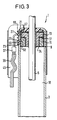
- the embodiment shown in Fig. 3 differs from that shown in Fig. 1 in that the ignition unit 45 similar to that in Fig. 2 shown ignition unit 35 as an elongated, to the Shell surface of the cylinder 3 conforming body is formed and does not clearly protrude laterally from it as in FIG. 1.
- Both Through openings 21, 23 are, however, like that shown in FIG. 1 Embodiment, provided in the outer surface of the cylinder 3.
- the Housing 11 is in the areas 57, 58 of the through openings 21, 23 closed, but e.g. through an annular groove or through a perforation weakened to break through the housing 11 when igniting facilitate.
- each squib 27, 29 is the ignition reinforcing jacket 55, 56 surrounded by pyrotechnic material, which in the embodiment shown in Fig. 3 in the corresponding Through opening 21, 23 protrudes.
- each propellant charge 13, 15 is its own Ignition unit 49 or 51 assigned, the ignition units 49, 51 are each designed as a plug-in connection by connecting them with an im Cross section of smaller extension 53 in a correspondingly larger design Through openings 21, 23 on the outer surface of the cylinder 3 with Press fit.
- the operation of the linear drive device 1 is based on Fig. 1 explained below.
- the vehicle will over a crash sensor sends a corresponding signal to the triggering device 31 fed.
- This initiates, depending on whether a seat is occupied or not, and controls, depending on the body weight of the vehicle occupant Height and sitting position triggering one or both Propellant charges 13, 15 via the ignition unit 25. Is via the sensors determines that the linear drive device 1 for a small, light vehicle occupants should be triggered, only the first Propellant charge 13 triggered by the squib 27, and gas flows into the Work space 18.
- the cover 19 is penetrated.
- the Front cover 20 which has not been destroyed by the gas pressure prevents the ignited propellant charge 13 from igniting Propellant charge 15 is triggered.
- the ignited propellant charge 13 is igniting Propellant charge 15 is triggered.
- the triggered Propellant charge is assigned.
Landscapes
- Engineering & Computer Science (AREA)
- Mechanical Engineering (AREA)
- General Engineering & Computer Science (AREA)
- Automotive Seat Belt Assembly (AREA)
- Power-Operated Mechanisms For Wings (AREA)
- Connection Of Motors, Electrical Generators, Mechanical Devices, And The Like (AREA)
- Air Bags (AREA)
Abstract
Description
- Fig. 1 eine Längsschnittansicht durch eine erste Ausführungsform der erfindungsgemäßen Linearantriebseinrichtung, mit einem im Inneren des Zylinders angeordneten Gasgenerator mit zwei Treibladungen, die über eine gemeinsame Zündeinheit auslösbar sind;
- Fig. 2 eine entsprechende Ansicht einer zweiten Ausführungsform der erfindungsgemäßen Linearantriebseinrichtung, bei der die von zwei Treibladungen gefüllten Räume im Inneren des Gasgenerators jedoch eine andere Geometrie aufweisen als bei der in Fig. 1 gezeigten Ausführungsform;
- Fig. 3 eine entsprechende Ansicht einer dritten Ausführungsform der erfindungsgemäßen Linearantriebseinrichtung, mit einer gegenüber der in Fig. 1 gezeigten, modifizierten Zündeinheit; und
- Fig. 4 eine vierte Ausführungsform der erfindungsgemäßen Linearantriebseinrichtung mit zwei getrennten Zündeinheiten für die Treibladungen.
Claims (11)
- Pyrotechnische Linearantriebseinrichtung für einen Gurtstraffer, mit einer Kolben-Zylinder-Einheit, einem Gasgenerator (9; 9'), zum Antreiben des Kolbens und einer Zündeinheit (25; 35; 45; 49, 51) zum Auslösen einer Treibladung (13, 15) des Gasgenerators (9; 9'), dadurch gekennzeichnet, daß der Gasgenerator (9; 9') als Mehrstufengasgenerator mit mehreren in seinem Inneren räumlich voneinander getrennten und getrennt einzeln oder gleichzeitig auslösbaren Treibladungen (13, 15) ausgebildet ist.
- Linearantriebseinrichtung nach Anspruch 1, dadurch gekennzeichnet, daß ihr zumindest ein Sensor (33) zur Ermittlung von fahrzeuginsassen-, fahrzeug- oder fahrzeugumgebungsspezifischen Parametern sowie ein damit verbundenes Auslösegerät (31) zugeordnet sind, das in Abhängigkeit von den ermittelten Parametern die Auslösung von einer oder mehreren Treibladungen (13, 15) steuert.
- Linearantriebseinrichtung nach Anspruch 1 oder 2, dadurch gekennzeichnet, daß Sensoren zur Ermittlung von einem oder mehreren der folgenden Parameter vorgesehen sind:Sitzbelegung,Körpergewicht des Fahrzeuginsassen,Körpergröße des Fahrzeuginsassen,Sitzposition des Fahrzeuginsassen im Fahrzeug,Aufprallintensität,Fahrzeuginnenraumtemperatur undAußentemperatur.
- Linearantriebseinrichtung nach einem der vorstehenden Ansprüche, dadurch gekennzeichnet, daß die Treibladungen (13, 15) unterschiedliche Antriebsleistungen haben.
- Linearantriebseinrichtung nach einem der vorstehenden Ansprüche, gekennzeichnet durch eine gemeinsame Zündeinheit (25; 35; 45) für die Treibladungen (13, 15) mit jeweils einer, einem Treibsatz (13, 15) zugeordneten Zündpille (27, 29).
- Linearantriebseinrichtung nach Anspruch 5, dadurch gekennzeichnet, daß jede Zündpille (27, 29) von einem die Zündung verstärkenden Mantel (55, 56) aus pyrotechnischem Material umgeben ist.
- Linearantriebseinrichtung nach Anspruch 5 oder 6, dadurch gekennzeichnet, daß ein gemeinsames, sich in die Zündeinheit (25; 35; 45) erstreckendes Kabel (39) und eine gemeinsame, in die Zündeinheit (25) integrierte Hochfrequenzdrossel (37) für sämtliche Zündpillen (27, 29) vorgesehen sind, wobei sich Adern des Kabels (39) nach der Hochfrequenzdrossel (37) zu den einzelnen Zündpillen (27, 29) aufzweigen und die Hochfrequenzdrossel (37) in der gemeinsamen Masseleitung der Zündpillen (27, 29) angeordnet ist.
- Linearantriebseinrichtung nach einem der vorstehenden Ansprüche, dadurch gekennzeichnet, daß die mindestens eine Zündeinheit (49, 51) zu ihrer Befestigung eine Steckverbindung aufweist oder Teil einer Steckverbindung ist.
- Linearantriebseinrichtung nach einem der vorstehenden Ansprüche, dadurch gekennzeichnet, daß der Gasgenerator (9; 9') ein kreisringförmiger Körper ist, der im Inneren des Zylinders (3) an die Zylinderwandung angrenzt, wobei im Inneren des Gasgenerators (9; 9') eine Trennwand (17; 17') zwischen den Treibladungen (13, 15) vorgesehen ist, die insgesamt axial verläuft.
- Linearantriebseinrichtung nach Anspruch 9, dadurch gekennzeichnet, daß die Treibladungen (13, 15) koaxiale, kreisringförmige Räume im Gasgenerator (9; 9') ausfüllen, die jeweils in den Arbeitsraum (18) im Inneren des Zylinders (3) münden, wobei im nicht ausgelösten Zustand jede Treibladung (13, 15) durch eine stirnseitige Abdeckung (19, 20) zum Arbeitsraum (18) hin abgetrennt und gegen Auslösen beim Zünden einer anderen Treibladung (13, 15) geschützt ist.
- Linearantriebseinrichtung nach Anspruch 9 oder 10, dadurch gekennzeichnet, daß das Gehäuse (11) des Gasgenerators (9) im Bereich (57, 58) von den Zündpillen (27, 29) gegenüberliegenden Durchgangsöffnungen (21, 23) in der Zylinderwandung jeweils geschwächt ist, um das Durchbrechen des Gehäuses (11) beim Zünden der entsprechenden Treibladung (13, 15) zu erleichtern.
Applications Claiming Priority (2)
| Application Number | Priority Date | Filing Date | Title |
|---|---|---|---|
| DE29612781U | 1996-07-23 | ||
| DE29612781U DE29612781U1 (de) | 1996-07-23 | 1996-07-23 | Pyrotechnische Linearantriebseinrichtung für einen Gurtstraffer |
Publications (2)
| Publication Number | Publication Date |
|---|---|
| EP0820910A2 true EP0820910A2 (de) | 1998-01-28 |
| EP0820910A3 EP0820910A3 (de) | 2000-07-19 |
Family
ID=8026876
Family Applications (1)
| Application Number | Title | Priority Date | Filing Date |
|---|---|---|---|
| EP97111648A Withdrawn EP0820910A3 (de) | 1996-07-23 | 1997-07-09 | Pyrotechnische Linearantriebseinrichtung für einen Gurtstraffer |
Country Status (7)
| Country | Link |
|---|---|
| US (1) | US6079745A (de) |
| EP (1) | EP0820910A3 (de) |
| JP (1) | JPH1059130A (de) |
| KR (1) | KR980008880A (de) |
| BR (1) | BR9705226A (de) |
| DE (1) | DE29612781U1 (de) |
| ES (1) | ES2115574T1 (de) |
Cited By (1)
| Publication number | Priority date | Publication date | Assignee | Title |
|---|---|---|---|---|
| EP0940307A3 (de) * | 1998-03-04 | 2002-01-09 | Takata Corporation | Sicherheitsgurtvorrichtung, Gurtstrammer, und Fahrzeug |
Families Citing this family (34)
| Publication number | Priority date | Publication date | Assignee | Title |
|---|---|---|---|---|
| US6891111B1 (en) | 1994-02-04 | 2005-05-10 | Siemens Vdo Automotive Corporation | Signal processing in a vehicle classification system |
| DE29608194U1 (de) * | 1996-05-06 | 1996-10-02 | Trw Occupant Restraint Systems Gmbh, 73551 Alfdorf | Elektrischer Zünder eines pyrotechnischen Gasgenerators |
| DE29611657U1 (de) * | 1996-07-04 | 1996-11-07 | Trw Occupant Restraint Systems Gmbh, 73551 Alfdorf | Sicherheitseinrichtung für Fahrzeuge |
| US5873599A (en) * | 1997-05-13 | 1999-02-23 | Trw Vehicle Safety Systems Inc. | Apparatus for pretensioning seat belt webbing |
| DE29717367U1 (de) * | 1997-09-29 | 1998-02-12 | Trw Occupant Restraint Systems Gmbh, 73551 Alfdorf | Pyrotechnischer Antrieb, insbesondere für Fahrzeuginsassen-Rückhaltesysteme |
| KR20010031876A (ko) * | 1997-11-12 | 2001-04-16 | 웰스 러셀 씨 | 차량 좌석 착석 승객의 중량과 위치를 결정하는 방법 및시스템 |
| US6032979C1 (en) † | 1998-02-18 | 2001-10-16 | Autoliv Asp Inc | Adaptive output inflator |
| US6447010B1 (en) | 1999-06-30 | 2002-09-10 | Siemens Vdo Automotive Corporation | Seat belt force sensor system |
| DE19941435C2 (de) * | 1999-08-30 | 2001-08-09 | Autoliv Dev | Mehrstufige Sicherheitsgurt-Straffvorrichtung |
| US6814372B1 (en) * | 1999-11-05 | 2004-11-09 | Ford Global Technologies, Llc | Method for apparatus for venting an inflatable restraint assembly |
| DE10005010C2 (de) | 2000-02-04 | 2002-11-21 | Daimler Chrysler Ag | Verfahren und Sicherheits-Rückhalteeinrichtung zum Zurückhalten eines Insassen auf einem Fahrzeugsitz |
| DE60112049T2 (de) | 2000-02-25 | 2006-03-16 | Siemens Vdo Automotive Corp., Auburn Hills | Signalverarbeitung in einem fahrzeuggewichtklassifikationssystem |
| KR20030043791A (ko) * | 2000-05-12 | 2003-06-02 | 지멘스 비디오 오토모티브 코포레이션 | 시트벨트력 센서 시스템 |
| US6636792B2 (en) | 2000-09-29 | 2003-10-21 | Siemens Vdo Automotive Corporation | Weight classification system |
| US6793032B2 (en) | 2000-09-29 | 2004-09-21 | Siemens Vdo Automotive Corporation | Seatbelt force sensor assembly with guide member |
| US6662670B2 (en) | 2000-10-02 | 2003-12-16 | Siemens Vdo Automotive Corporation | Seatbelt force sensor with overload protection |
| SE517378C2 (sv) | 2000-10-12 | 2002-06-04 | Volvo Car Corp | Säkerhetsbältesförsträckare |
| US6641074B2 (en) * | 2001-01-08 | 2003-11-04 | Trw Inc. | Seat belt webbing pretensioner using MEMS devices |
| DE10227755B4 (de) * | 2002-06-21 | 2004-07-22 | Autoliv Development Ab | Pyrotechnischer Schloßstraffer |
| US7182191B2 (en) * | 2002-07-11 | 2007-02-27 | Autoliv Asp, Inc. | Motion damper |
| US6764118B2 (en) | 2002-09-11 | 2004-07-20 | Autoliv Asp, Inc. | Active bumper assembly |
| US6942261B2 (en) | 2003-08-14 | 2005-09-13 | Autoliv Asp, Inc. | Linear actuator with an internal dampening mechanism |
| DE602004028440D1 (de) * | 2004-05-04 | 2010-09-16 | Ford Global Tech Llc | Sicherheitsgurt-Rückhaltesystem |
| US7303040B2 (en) * | 2004-05-18 | 2007-12-04 | Autolive Asp, Inc. | Active vehicle hood system and method |
| US7448649B2 (en) * | 2004-11-17 | 2008-11-11 | Automotive Systems Laboratory, Inc. | Gas generator |
| DE102005051657A1 (de) * | 2005-10-28 | 2007-05-03 | GM Global Technology Operations, Inc., Detroit | Pyrotechnischer Aktuator |
| KR100863633B1 (ko) | 2006-10-31 | 2008-10-15 | 현대자동차주식회사 | 차량용 에어백의 복합뇌관 장치 및 그 제어방법 |
| US10281248B2 (en) * | 2015-11-11 | 2019-05-07 | Northrop Grumman Innovation Systems, Inc. | Gas generators, launch tube assemblies including gas generators, and related systems and methods |
| US10974626B2 (en) | 2019-09-12 | 2021-04-13 | Ford Global Technologies, Llc | Seat assembly with integrated belt member |
| US11124147B2 (en) | 2019-09-17 | 2021-09-21 | Ford Global Technologies, Llc | Seat assembly with deployable belt member |
| US11958435B2 (en) | 2022-06-21 | 2024-04-16 | Ford Global Technologies, Llc | Seat assembly with deployable belt member |
| US11975680B2 (en) | 2022-06-21 | 2024-05-07 | Ford Global Technologies, Llc | Seat assembly with deployable belt member |
| US11904795B2 (en) | 2022-06-21 | 2024-02-20 | Ford Global Technologies, Llc | Seat assembly with deployable belt member |
| US12311869B2 (en) | 2022-06-21 | 2025-05-27 | Ford Global Technologies, Llc | Seat assembly with deployable belt member |
Family Cites Families (21)
| Publication number | Priority date | Publication date | Assignee | Title |
|---|---|---|---|---|
| DE2540952C2 (de) * | 1975-09-13 | 1984-08-16 | Volkswagenwerk Ag, 3180 Wolfsburg | Gurtspannvorrichtung für einen Sicherheitsgurt |
| DE2816726A1 (de) * | 1978-04-18 | 1979-10-31 | Daimler Benz Ag | Insassen-rueckhaltesystem fuer fahrzeuge |
| US5145209A (en) * | 1990-02-13 | 1992-09-08 | Trw Vehicle Safety Systems Inc. | Seat belt pretensioner |
| US5200574A (en) * | 1991-04-05 | 1993-04-06 | Morton International, Inc. | Universal squib connector |
| EP0558963B1 (de) * | 1992-03-05 | 1997-10-01 | TRW Occupant Restraint Systems GmbH | Linearantrieb für Fahrzeugrückhaltesysteme |
| DE4222985A1 (de) * | 1992-05-05 | 1993-11-11 | Trw Repa Gmbh | Linearantrieb für einen Gurtstraffer |
| DE4217969C2 (de) * | 1992-05-30 | 1994-11-03 | Autoflug Gmbh | Gurtstraffer mit mehrstufigem Antrieb |
| GB2267813B (en) * | 1992-06-19 | 1997-01-29 | Nsk Ltd | Seat belt tightening device |
| DE4307062A1 (de) * | 1993-03-06 | 1994-09-08 | Trw Repa Gmbh | Gurtstraffer für Sicherheitsgurtsysteme in Fahrzeugen |
| DE9303276U1 (de) * | 1993-03-06 | 1993-04-22 | TRW Repa GmbH, 7077 Alfdorf | Gurtstraffer in einem Sicherheitsgurtsystem für Fahrzeuge |
| DE9304152U1 (de) * | 1993-03-20 | 1993-05-13 | TRW Repa GmbH, 7077 Alfdorf | Gurtstraffer mit pyrotechnischem Gasgenerator |
| DE4332206C2 (de) * | 1993-09-22 | 1997-08-14 | Hs Tech & Design | Antriebsvorrichtung |
| US5400487A (en) * | 1994-01-14 | 1995-03-28 | Automotive Systems Laboratory, Inc. | Variable inflation system for vehicle safety restraint |
| EP0680856A3 (de) * | 1994-05-06 | 1996-03-06 | Hs Tech & Design | Vorrichtung zum Drehantrieb eines Sicherheitsgurtstraffers. |
| WO1996000157A1 (en) * | 1994-06-27 | 1996-01-04 | Nippon Koki Co., Ltd. | Gas producer for seat belt take-up power generating device |
| US5568940A (en) * | 1994-07-27 | 1996-10-29 | Trw Vehicle Safety Systems Inc. | Belt tightener for a vehicle safety belt system |
| US5564743A (en) * | 1995-03-22 | 1996-10-15 | Morton International, Inc. | Multiple stage air bag inflator system |
| US5622380A (en) * | 1995-09-21 | 1997-04-22 | Automotive Systems Laboratory, Inc. | Variable nonazide gas generator having multiple propellant chambers |
| US5704638A (en) * | 1995-12-18 | 1998-01-06 | Alliedsignal Inc. | Integrated side impact inflator and module with seat belt pretensioning capability |
| DE29608194U1 (de) * | 1996-05-06 | 1996-10-02 | Trw Occupant Restraint Systems Gmbh, 73551 Alfdorf | Elektrischer Zünder eines pyrotechnischen Gasgenerators |
| US5863009A (en) * | 1997-12-24 | 1999-01-26 | Trw Vehicle Safety Systems Inc. | Apparatus for pretensioning seat belt webbing |
-
1996
- 1996-07-23 DE DE29612781U patent/DE29612781U1/de not_active Expired - Lifetime
-
1997
- 1997-07-09 ES ES97111648T patent/ES2115574T1/es active Pending
- 1997-07-09 EP EP97111648A patent/EP0820910A3/de not_active Withdrawn
- 1997-07-14 US US08/892,117 patent/US6079745A/en not_active Expired - Fee Related
- 1997-07-21 KR KR1019970033931A patent/KR980008880A/ko not_active Withdrawn
- 1997-07-22 BR BR9705226A patent/BR9705226A/pt not_active Application Discontinuation
- 1997-07-23 JP JP9197142A patent/JPH1059130A/ja active Pending
Cited By (1)
| Publication number | Priority date | Publication date | Assignee | Title |
|---|---|---|---|---|
| EP0940307A3 (de) * | 1998-03-04 | 2002-01-09 | Takata Corporation | Sicherheitsgurtvorrichtung, Gurtstrammer, und Fahrzeug |
Also Published As
| Publication number | Publication date |
|---|---|
| JPH1059130A (ja) | 1998-03-03 |
| DE29612781U1 (de) | 1996-11-21 |
| MX9705552A (es) | 1998-05-31 |
| KR980008880A (ko) | 1998-04-30 |
| EP0820910A3 (de) | 2000-07-19 |
| BR9705226A (pt) | 1999-03-23 |
| US6079745A (en) | 2000-06-27 |
| ES2115574T1 (es) | 1998-07-01 |
Similar Documents
| Publication | Publication Date | Title |
|---|---|---|
| DE29612781U1 (de) | Pyrotechnische Linearantriebseinrichtung für einen Gurtstraffer | |
| DE69831625T2 (de) | Gurtstraffer | |
| DE69608332T2 (de) | Pyrotechnischer Aufblaser für einen Kraftfahrzeug-Gassack | |
| DE19848592B4 (de) | Airbag mit Abschirmung | |
| DE19918596B4 (de) | Vorrichtung zum Straffen eines Sicherheitsgurtes | |
| DE4007551C2 (de) | Gasgenerator | |
| DE19642938C2 (de) | Airbagmodul für einen Fahrzeugsitz | |
| DE60204742T2 (de) | Gasgenerator für Air-bag | |
| EP0782945B1 (de) | Gasgenerator für ein Fahrzeug-Rückhaltesystem | |
| DE2629462A1 (de) | Filter | |
| DE102010027401A1 (de) | Seitengassack zum Einbau in ein Kraftfahrzeug, Fahrzeugsitz mit einem solchen Seitengassack und Kraftfahrzeug | |
| DE2436754A1 (de) | Durch explosiv-treibstoff betaetigte sicherheitsgurt-spannvorrichtung mit mechanischer stossdaempfung | |
| EP0803412B1 (de) | Sicherheitsgurtsystem | |
| DE19860840A1 (de) | Airbagvorrichtung, Fahrzeuginnenverkleidung zur Abdeckung einer Airbagvorrichtung, Sitz mit einer Airbagvorrichtung und Auslöseverfahren einer Airbagvorrichtung | |
| DE102008028921B4 (de) | Gassackmodul für ein Fahrzeug-Sicherheitssystem | |
| WO2016142083A1 (de) | Gassackmodul und fahrzeug | |
| DE19742584A1 (de) | Luftsackeinrichtung | |
| DE19733896A1 (de) | Airbagvorrichtung | |
| DE19703945A1 (de) | Airbagvorrichtung in einem Kraftfahrzeug | |
| DE69013778T2 (de) | Anordnung zum Formen einer Öffnung zum Aufblasen eines Luftkissens. | |
| DE102007009036A1 (de) | Gasgenerator für eine Rückhaltevorrichtung für Fahrzeuge | |
| DE19839283A1 (de) | Airbag-Modul mit Gasverteiler | |
| DE19633696B4 (de) | Airbagabdeckklappe | |
| EP0836565A1 (de) | Pyrotechnische antriebseinrichtung für einen gurtstraffer | |
| DE19641224B4 (de) | Antriebsvorrichtung, insbesondere zum Straffen eines Sicherheitsgurtes in einem Kraftfahrzeug |
Legal Events
| Date | Code | Title | Description |
|---|---|---|---|
| PUAI | Public reference made under article 153(3) epc to a published international application that has entered the european phase |
Free format text: ORIGINAL CODE: 0009012 |
|
| AK | Designated contracting states |
Kind code of ref document: A2 Designated state(s): DE ES FR GB IT |
|
| AX | Request for extension of the european patent |
Free format text: AL;LT;LV;RO;SI |
|
| GBC | Gb: translation of claims filed (gb section 78(7)/1977) | ||
| ITCL | It: translation for ep claims filed |
Representative=s name: DR. ING. A. RACHELI & C. |
|
| EL | Fr: translation of claims filed | ||
| RAP1 | Party data changed (applicant data changed or rights of an application transferred) |
Owner name: TRW OCCUPANT RESTRAINT SYSTEMS GMBH & CO. KG |
|
| REG | Reference to a national code |
Ref country code: ES Ref legal event code: BA2A Ref document number: 2115574 Country of ref document: ES Kind code of ref document: T1 |
|
| PUAL | Search report despatched |
Free format text: ORIGINAL CODE: 0009013 |
|
| AK | Designated contracting states |
Kind code of ref document: A3 Designated state(s): AT BE CH DE DK ES FI FR GB GR IE IT LI LU MC NL PT SE |
|
| AX | Request for extension of the european patent |
Free format text: AL;LT;LV;RO;SI |
|
| RIC1 | Information provided on ipc code assigned before grant |
Free format text: 7B 60R 22/46 A, 7F 42B 3/04 B |
|
| 17P | Request for examination filed |
Effective date: 20001116 |
|
| AKX | Designation fees paid |
Free format text: DE ES FR GB IT |
|
| STAA | Information on the status of an ep patent application or granted ep patent |
Free format text: STATUS: THE APPLICATION IS DEEMED TO BE WITHDRAWN |
|
| 18D | Application deemed to be withdrawn |
Effective date: 20020201 |