EP0820932B1 - Nadel zum Befestigen von Befestigungselementen - Google Patents
Nadel zum Befestigen von Befestigungselementen Download PDFInfo
- Publication number
- EP0820932B1 EP0820932B1 EP97112420A EP97112420A EP0820932B1 EP 0820932 B1 EP0820932 B1 EP 0820932B1 EP 97112420 A EP97112420 A EP 97112420A EP 97112420 A EP97112420 A EP 97112420A EP 0820932 B1 EP0820932 B1 EP 0820932B1
- Authority
- EP
- European Patent Office
- Prior art keywords
- connection filament
- conical portion
- anchor
- inserting apparatus
- opening
- Prior art date
- Legal status (The legal status is an assumption and is not a legal conclusion. Google has not performed a legal analysis and makes no representation as to the accuracy of the status listed.)
- Expired - Lifetime
Links
Images

Classifications
-
- B—PERFORMING OPERATIONS; TRANSPORTING
- B65—CONVEYING; PACKING; STORING; HANDLING THIN OR FILAMENTARY MATERIAL
- B65C—LABELLING OR TAGGING MACHINES, APPARATUS, OR PROCESSES
- B65C7/00—Affixing tags
- B65C7/003—Affixing tags using paddle-shaped plastic pins
-
- B—PERFORMING OPERATIONS; TRANSPORTING
- B21—MECHANICAL METAL-WORKING WITHOUT ESSENTIALLY REMOVING MATERIAL; PUNCHING METAL
- B21G—MAKING NEEDLES, PINS OR NAILS OF METAL
- B21G1/00—Making needles used for performing operations
- B21G1/08—Making needles used for performing operations of hollow needles or needles with hollow end, e.g. hypodermic needles, larding-needles
Definitions
- the present invention relates to a connection filament inserting apparatus for inserting a connection filament through clothes or the like in order to attach a tag with the connection filament to the clothes, and to a method for manufacturing the connection filament inserting apparatus.
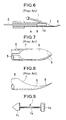
- connection filament inserting apparatus A comprises a body 8 of a hollow needle-shape which has an opening 7, and a spoon-shaped tip 6 at one end of the body 8.
- connection filament 1 when it is in use.
- the connection filament 1 comprises a filament body la, an anchor 1b formed at the one end of the filament body la, and a triangular connecting portion 1c to which a price tag or the like is attached.
- the filament body la and the anchor 1b are connected to form a T-shape.
- connection filament 1 When the connection filament 1 is attached to the clothes with the connection filament inserting apparatus A, the anchor 1b is inserted into the apparatus A in advance, the apparatus A is inserted through the clothes, the anchor 1b is pushed out from the opening 7 by a push rod 3, and the apparatus A is pulled out from the clothes. The anchor 1b is caught in the clothes to prevent the connection filament 1 from falling out from the clothes, and the tag is attached to the clothes.
- connection filament 1 With such a connection filament inserting apparatus A, the connection filament 1 can be easily attached to clothes.
- the sharp edges 9 at both sides may cut the fibers of the clothes in a manner similar to a knife, and the clothes may thereby be damaged.
- connection filament inserting apparatus A Because the tip 6 has less bending strength because the sectional size at the tip 6 is small, the tip 6 may be accidentally bent or broken when the connection filament inserting apparatus A pierces the clothes. Such connection filament inserting apparatus A cannot be used for products through which it is difficult to pass the inserting apparatus, such as a stiff cloth, a carpet, and leather goods. If the tip 6 is bent and the opening 7 is deformed when the connection filament inserting apparatus A is used, the user may injure himself.
- connection filament inserting apparatus which has sufficient strength and durability and which can be safely handled, and a method for manufacturing the connection filament inserting apparatus.
- connection filament inserting apparatus of the present invention for inserting a T-shaped anchor of a connection filament through an article, comprising:
- the apparatus because the apparatus is inserted through the clothes so as to make the conical portion lead, which does not have any sharp edge, the clothes are not cut or damaged in the inserting procedure. Furthermore, because the sectional size at the conical portion is large, the conical portion has sufficient bending strength and durability and is prevented from being accidentally bent or broken. Accordingly, it is also possible to insert the apparatus through a stiff product and to safely handle the apparatus.
- connection filament inserting apparatus the inside of the conical portion is filled with a filler forming a guide surface.
- the guide surface is preferably formed to rise from the inside face of the body and to extend to the edge of the opening. According to the apparatus, the anchor is guided by the guide surface so as to be smoothly released from the opening.
- connection filament inserting apparatus further comprises a slit from the opening to the opposite end of the tip. According to this apparatus, the connection filament is removed smoothly through the slit.
- the apparatus further comprises a holder which is connected to the rear of the body. The user can thereby easily handle the apparatus.
- connection filament inserting apparatus for inserting a T-shaped anchor of a connection filament through an article, comprising the steps of: stamping out a metal plate by a press die; bending the metal plate to form a hollow body having a front end, a rear end, an inner space for accommodating the anchor, and a pointed conical portion formed at one end of the body, wherein the hollow body has an opening formed at the rear side of the conical portion for releasing the anchor from the inner space of the body; immersing the conical portion in filler; and pulling up the conical portion in order to solidify the filler remaining in the conical portion so as to form a guide surface for guiding the anchor when the anchor is released from the opening.
- Figure 1 shows an upper view of a connection filament inserting apparatus according to the present invention.
- Figure 2 is a rear view of the connection filament inserting apparatus according to the present invention.
- Figure 3 is a cross section along the line X-X in Figure 1.
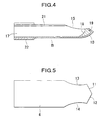
- Figure 4 is a cross section of the connection filament inserting apparatus in which the conical portion thereof is filled with a filler according to the present invention.
- Figure 5 is a metal plate as a material for the body of the connection filament inserting apparatus according to the present invention.
- Figure 6 is a cross section of a connection filament inserting apparatus of the prior art.
- Figure 7 is an upper view of the tip of the connection filament inserting apparatus of the prior art.
- Figure 8 is an side view of the tip of the connection filament inserting apparatus of the prior art.
- Figure 9 is a perspective view of a connection filament currently in use.
- connection filament inserting apparatus Referring to Figures 1 to 5, the embodiments of the connection filament inserting apparatus according to the present invention will be explained.
- connection filament inserting apparatus B comprises a body 21 of a hollow needle-shape having an inner space 17, and a pointed conical portion 10 formed at front end of the body 21.
- the body 21 has an elliptic opening 15 at a position closer to the conical portion 10.
- the inside rim of the opening 15 is formed to be chamfered corner.
- the major axis of the opening 15 is set equal to the diameter of the body 21.
- the conical portion 10 comprises a conical face 10b which is slightly curved outside, and the sharp tip 10a which is surrounded by the conical face 10b.
- a slit 16 is formed at the upper side of the body 21 so as to extend from the opening 15 to the rear end of the body 21.
- the rear end of the body 21 is inserted into a cylinder-shaped holder 22, with which an operator can easily handle the connection filament inserting apparatus B.
- the anchor 1b When a tag with the connection filament 1 is attached to the clothes, the anchor 1b is inserted into the apparatus B in advance, the apparatus B is inserted through the clothes so as to make the conical portion 10 lead. After the anchor 1b is deeply inserted, the anchor 1b is pushed out from the opening 15 by a push rod (not shown), the apparatus B is pulled out from the clothes, and thus, the anchor 1b is caught in the clothes.
- the conical portion 10 lacks sharp edges and is inserted through the clothes first, the clothes are not cut or damaged. Furthermore, because the sectional size at the conical portion 10 is large, the conical portion 10 has sufficient bending strength and durability and is prevented from being accidentally bent or broken. It is also possible to insert the apparatus B through a tough product, such as a stiff cloth, a carpet, and leather goods, and to safely handle the apparatus B.
- the inside of the conical portion 10 may be hollow. If the anchor 1b is longer than the width of the opening 15, it may be caught at the edge of the opening 15, the inside of the conical portion 10 is preferably filled with the filler 19 such as hard plastic or fusible metal as shown in Figure 4.
- the filler 19 is formed to have a guide surface 18 which rises from the inside face of the body 21 and extends to the edge of the opening 15.
- connection filament 1 When the connection filament 1 is inserted through the clothes with the apparatus B, the anchor 1b is pushed out by the push rod. In this procedure, the anchor 1b is guided by the guide surface 18 so as to be smoothly released from the opening 15.
- connection filament inserting apparatus B A method for manufacturing the connection filament inserting apparatus B will be explained.
- a metal plate 4 of a scherd-shape as shown in Figure 5 is stamped out by a press die.
- the shape of the metal plate 4 comprises left and right tip edges 11 and 12 which form a sharp tip, and left and right side edges 13 and 14 which are curved toward the inside.
- the metal plate 4 is bent by press working and the left and right tip edges 11 and 12 are joined so that the hollow body 21 is formed.
- the opening 15 is formed by the left and right side edges 13 and 14 on the upper side of the body 21, and the slit 16 is formed at the seam of the upper side of the body 21.
- the body 21 is inserted into the holder 22.
- the conical portion 10 In order to fill the inside of the conical portion 10 with the filler 19 such as hard plastic or fusible metal, the conical portion 10 is immersed in melted plastic or metal such as lead, tin, or an alloy of lead and tin. The conical portion 10 is pulled up, and the filler solidifies in the conical portion 10 so that the guide surface 18 is formed.
- the filler 19 such as hard plastic or fusible metal
- the material of the filler 19 and the metal plate 4 may be appropriately selected.
- the metal plate 4 is made of stainless steel in view of workability and hardenablity.
- the metal material is not limited, and the other metal material having appropriate workability, hardenablity, and adhesion, can be also applied.
- insertion injection molding method generally used in the process of metal material can be also applied.
Landscapes
- Engineering & Computer Science (AREA)
- Mechanical Engineering (AREA)
- Labeling Devices (AREA)
- Sewing Machines And Sewing (AREA)
Claims (5)
- Eine Etikettierschlaufen-Einziehvorrichtung für das Durchführen des Ankers (1b) einer Etikettierschlaufe (a) durch einen Gegenstand, bestehend aus:dadurch gekennzeichnet, dasseinem Hohlkörper (21) mit einem vorderen Ende, einem hinteren Ende und einem Innenraum für die Aufnahme des besagten Ankers; undeinem spitz auslaufenden konischen Teil (10)m der an einem Ende des besagten Körpers ausgebildet ist;wobei der besagte Hohlkörper eine Öffnung zum Freigeben des besagtn Ankers aus dem besagten Innenraum des besagten Körpers aufweist,der besagte Hohlkörper aus einem Metallblech (4) besteht, wobei die besagte Öffnung in dem besagten konischen Teil (10) ausgebildet ist, und das Innere des besagten konischen Teils (10) mit einem leicht schmelzbaren Füllmaterial (19) ausgefüllt ist, das eine Führungsfläche (18) für das Führen des besagten Ankers (1b) bildet;das Füllmaterial (19) aus einem harten Plastwerkstoff oder einem leicht schmelzbaren Metall wie Blei, Zinn oder einer Legierung daraus besteht;das Füllmaterial (19) auf den konischen Teil (10) entweder durch Eintauchen in die geschmolzene Füllstoffmasse, anschließendes Herausziehen und Verfestigen oder durch Spritzgießen der Füllstoffmasse in den konischen Teil (10) und Verfestigenlassen aufgebracht wird.
- Etikettierschlaufen-Einziehvorrichtung gemäß Anspruch 1, bei der die besagte Führungsfläche (18) so geformt ist, dass sie von einer Innenfläche des besagten Hohlkörpers (21) ansteigt und sich bis zum Rand der besagten Öffnung (15) erstreckt.
- Etikettierschlaufen-Einziehvorrichtung gemäß Anspruch 1, die außerdem einen Schlitz (16) enthält, der sich von der besagten Öffnung bis zu dem besagten hinteren Ende des besagten Körpers erstreckt, durch den die besagte Etikettierschlaufe führt.
- Etikettierschlaufen-Einziehvorrichtung gemäß Anspruch 1, die außerdem eine Halterung (22) enthält, die mit dem besagten hinteren Ende des besagten Körpers verbunden ist.
- Etikettierschlaufen-Einziehvorrichtung gemäß Anspruch 1, bei der der besagte Hohlkörper (21) durch Ausstanzen aus dem besagten Blech mittels eines Stanzwerkzeugs und Biegen des besagten Blechs gebildet wird.
Applications Claiming Priority (6)
| Application Number | Priority Date | Filing Date | Title |
|---|---|---|---|
| JP21324796 | 1996-07-25 | ||
| JP21324796 | 1996-07-25 | ||
| JP213247/96 | 1996-07-25 | ||
| JP13053497 | 1997-05-06 | ||
| JP13053497A JP3463256B2 (ja) | 1996-07-25 | 1997-05-06 | 中空針状物品及び中空針状物品の製造方法 |
| JP130534/97 | 1997-05-06 |
Publications (2)
| Publication Number | Publication Date |
|---|---|
| EP0820932A1 EP0820932A1 (de) | 1998-01-28 |
| EP0820932B1 true EP0820932B1 (de) | 2001-05-23 |
Family
ID=26465645
Family Applications (1)
| Application Number | Title | Priority Date | Filing Date |
|---|---|---|---|
| EP97112420A Expired - Lifetime EP0820932B1 (de) | 1996-07-25 | 1997-07-19 | Nadel zum Befestigen von Befestigungselementen |
Country Status (4)
| Country | Link |
|---|---|
| US (1) | US5924620A (de) |
| EP (1) | EP0820932B1 (de) |
| JP (1) | JP3463256B2 (de) |
| DE (1) | DE69704908T2 (de) |
Families Citing this family (10)
| Publication number | Priority date | Publication date | Assignee | Title |
|---|---|---|---|---|
| JP2003095233A (ja) * | 2001-09-21 | 2003-04-03 | Riyoukoushiya:Kk | 中空針状物品 |
| DE10248377A1 (de) | 2002-10-17 | 2004-05-06 | Haindl, Hans, Dr.med. | Kanüle, insbesondere für die Spinalanästhesie sowie Verfahren zu deren Herstellung |
| JP5012535B2 (ja) * | 2007-04-27 | 2012-08-29 | 豊田合成株式会社 | ウエザストリップ及びその製造方法 |
| FR2956416B1 (fr) * | 2010-02-18 | 2012-06-15 | Michelin Soc Tech | Aiguille pour l'insertion d'un fil dans un pneumatique |
| US11161642B2 (en) * | 2014-08-11 | 2021-11-02 | Avery Dennison Retail Information Services, Llc | Fastener assembly |
| KR101711907B1 (ko) * | 2015-05-27 | 2017-03-03 | 김동진 | 인출공 주위에 절곡부를 갖는 시술용 바늘 및 이를 가공하기 위한 장치 |
| KR101710707B1 (ko) * | 2016-07-12 | 2017-02-27 | 홍유리 | 캐뉼라의 제조방법 및 그 제조방법으로 제조된 캐뉼라 |
| US11465795B2 (en) | 2017-04-14 | 2022-10-11 | Avery Dennison Corporation | Automation for plastic disc |
| CN110923959B (zh) * | 2019-12-06 | 2021-06-29 | 山东省科创服饰有限公司 | 一种金属丝缝纫装置 |
| CN114568782A (zh) * | 2022-05-06 | 2022-06-03 | 杭州昌华户外旅游用品有限公司 | 一种服装生产用吊牌安装装置 |
Family Cites Families (12)
| Publication number | Priority date | Publication date | Assignee | Title |
|---|---|---|---|---|
| US29819A (en) * | 1860-08-28 | Eeatheb paddle-wheel | ||
| US2069878A (en) * | 1935-05-07 | 1937-02-09 | Dennison Mfg Co | Attaching means |
| ES379098A1 (es) * | 1970-02-04 | 1972-09-01 | Lozio Battista & Figli | Dispositivo para aplicar etiquetas a un cuerpo de soporte, como, por ejemplo,un tejido. |
| US3895753A (en) * | 1971-06-30 | 1975-07-22 | Dennison Mfg Co | Fastener attachment system needle constructions |
| USRE29819E (en) | 1973-07-26 | 1978-10-31 | Dennison Manufacturing Company | Fastener attachment system needle constructions |
| US4040555A (en) * | 1976-03-26 | 1977-08-09 | Monarch Marking Systems, Inc. | Tag attaching apparatus |
| DE3021799C2 (de) * | 1980-06-11 | 1982-05-13 | Heinz Hettich, Feinmechanik, 7743 Furtwangen | Verfahren zur Herstellung einer Hohlnadel für Etikettenbefestiger o.dgl. |
| US4535926A (en) * | 1983-11-30 | 1985-08-20 | Japan Bano'k Co., Ltd. | Fastener dispensing device |
| US4611740A (en) * | 1985-03-29 | 1986-09-16 | Kunreuther Steven J | Universal needle assembly for fastener attachers |
| US4785868A (en) * | 1987-06-04 | 1988-11-22 | Titan Medical, Inc. | Medical needle and method for making |
| US5588575A (en) * | 1994-09-13 | 1996-12-31 | Avery Dennison Corporation | Needle for use in the rodless dispensing of plastic fasteners |
| JP2913372B2 (ja) * | 1994-12-16 | 1999-06-28 | 株式会社コーテックス | 係止片取付機用中空針 |
-
1997
- 1997-05-06 JP JP13053497A patent/JP3463256B2/ja not_active Expired - Fee Related
- 1997-07-19 DE DE69704908T patent/DE69704908T2/de not_active Expired - Fee Related
- 1997-07-19 EP EP97112420A patent/EP0820932B1/de not_active Expired - Lifetime
- 1997-07-22 US US08/898,439 patent/US5924620A/en not_active Expired - Fee Related
Also Published As
| Publication number | Publication date |
|---|---|
| DE69704908D1 (de) | 2001-06-28 |
| DE69704908T2 (de) | 2001-11-15 |
| US5924620A (en) | 1999-07-20 |
| EP0820932A1 (de) | 1998-01-28 |
| JPH1091072A (ja) | 1998-04-10 |
| JP3463256B2 (ja) | 2003-11-05 |
Similar Documents
| Publication | Publication Date | Title |
|---|---|---|
| US3990619A (en) | Fastener attachment needle | |
| US5588575A (en) | Needle for use in the rodless dispensing of plastic fasteners | |
| EP0820932B1 (de) | Nadel zum Befestigen von Befestigungselementen | |
| US5669543A (en) | Hollow needle for tag attacher | |
| JP2613062B2 (ja) | 連結型結束具 | |
| CA2200474C (en) | Button fastener and clip | |
| US4266667A (en) | Package of mechanical pencil refill leads | |
| US5463799A (en) | Fastener for connecting materials with weakened portion | |
| GB2125343A (en) | Animal identification tag | |
| WO1997016359A1 (en) | Fixed circumference binding device with non-protruding free end and method for binding therewith | |
| US20030011096A1 (en) | Continuously connected fastener stock and method of manufacturing the same | |
| US6318553B1 (en) | Plastic fastener and needle well-suited for use in the dispensing thereof | |
| CA1325720C (en) | Animal ear tag-stud, animal ear tag-stud/support rod combination | |
| US7681730B2 (en) | Plastic fasteners, needles for dispensing and method of manufacture | |
| US6244490B1 (en) | Reactor plate assembly | |
| US6688509B2 (en) | Connection filament inserting apparatus | |
| KR100316757B1 (ko) | 중공침형상물품및중공침형상물품의제조방법 | |
| US5915614A (en) | Self-contained button attachment assembly | |
| US5897044A (en) | Needles useful in the dispensing of plastic fasteners | |
| JPH0428573Y2 (de) | ||
| EP0530406A1 (de) | Ohrmarke zur Identifizierung von Tieren und Werkzeug, um sie an einem Ohr anzubringen | |
| JP2000081011A (ja) | プラスチック段ボール板と補強板のかしめ締結方法及びその方法に用いられるかしめ用ポンチ並びにその方法によって得られるプラスチック段ボール箱 | |
| GB1600047A (en) | Card for the display of articles | |
| JPH0126730Y2 (de) | ||
| JPH11137144A (ja) | 中通し竿の釣糸通し具 |
Legal Events
| Date | Code | Title | Description |
|---|---|---|---|
| PUAI | Public reference made under article 153(3) epc to a published international application that has entered the european phase |
Free format text: ORIGINAL CODE: 0009012 |
|
| AK | Designated contracting states |
Kind code of ref document: A1 Designated state(s): CH DE IT LI |
|
| AX | Request for extension of the european patent |
Free format text: AL;LT;LV;RO;SI |
|
| 17P | Request for examination filed |
Effective date: 19980627 |
|
| RBV | Designated contracting states (corrected) |
Designated state(s): CH DE IT LI |
|
| 17Q | First examination report despatched |
Effective date: 19990818 |
|
| RTI1 | Title (correction) |
Free format text: FASTENER ATTACHERS INSERTING NEEDLE |
|
| GRAG | Despatch of communication of intention to grant |
Free format text: ORIGINAL CODE: EPIDOS AGRA |
|
| GRAG | Despatch of communication of intention to grant |
Free format text: ORIGINAL CODE: EPIDOS AGRA |
|
| GRAH | Despatch of communication of intention to grant a patent |
Free format text: ORIGINAL CODE: EPIDOS IGRA |
|
| GRAH | Despatch of communication of intention to grant a patent |
Free format text: ORIGINAL CODE: EPIDOS IGRA |
|
| GRAA | (expected) grant |
Free format text: ORIGINAL CODE: 0009210 |
|
| AK | Designated contracting states |
Kind code of ref document: B1 Designated state(s): CH DE IT LI |
|
| REG | Reference to a national code |
Ref country code: CH Ref legal event code: EP |
|
| REF | Corresponds to: |
Ref document number: 69704908 Country of ref document: DE Date of ref document: 20010628 |
|
| ITF | It: translation for a ep patent filed | ||
| REG | Reference to a national code |
Ref country code: CH Ref legal event code: NV Representative=s name: SCHMAUDER & PARTNER AG PATENTANWALTSBUERO |
|
| PLBE | No opposition filed within time limit |
Free format text: ORIGINAL CODE: 0009261 |
|
| STAA | Information on the status of an ep patent application or granted ep patent |
Free format text: STATUS: NO OPPOSITION FILED WITHIN TIME LIMIT |
|
| 26N | No opposition filed | ||
| PGFP | Annual fee paid to national office [announced via postgrant information from national office to epo] |
Ref country code: CH Payment date: 20050718 Year of fee payment: 9 |
|
| PGFP | Annual fee paid to national office [announced via postgrant information from national office to epo] |
Ref country code: DE Payment date: 20050914 Year of fee payment: 9 |
|
| PG25 | Lapsed in a contracting state [announced via postgrant information from national office to epo] |
Ref country code: LI Free format text: LAPSE BECAUSE OF NON-PAYMENT OF DUE FEES Effective date: 20060731 Ref country code: CH Free format text: LAPSE BECAUSE OF NON-PAYMENT OF DUE FEES Effective date: 20060731 |
|
| PGFP | Annual fee paid to national office [announced via postgrant information from national office to epo] |
Ref country code: IT Payment date: 20060731 Year of fee payment: 10 |
|
| PG25 | Lapsed in a contracting state [announced via postgrant information from national office to epo] |
Ref country code: DE Free format text: LAPSE BECAUSE OF NON-PAYMENT OF DUE FEES Effective date: 20070201 |
|
| REG | Reference to a national code |
Ref country code: CH Ref legal event code: PL |
|
| PG25 | Lapsed in a contracting state [announced via postgrant information from national office to epo] |
Ref country code: IT Free format text: LAPSE BECAUSE OF NON-PAYMENT OF DUE FEES Effective date: 20070719 |