EP0820952A2 - Méthode de répartition des cabines entre des navettes d'ascenseurs avec plateformes à plusieurs niveaux pour cabines - Google Patents
Méthode de répartition des cabines entre des navettes d'ascenseurs avec plateformes à plusieurs niveaux pour cabines Download PDFInfo
- Publication number
- EP0820952A2 EP0820952A2 EP97305588A EP97305588A EP0820952A2 EP 0820952 A2 EP0820952 A2 EP 0820952A2 EP 97305588 A EP97305588 A EP 97305588A EP 97305588 A EP97305588 A EP 97305588A EP 0820952 A2 EP0820952 A2 EP 0820952A2
- Authority
- EP
- European Patent Office
- Prior art keywords
- car frame
- level
- elevator
- hoistways
- hoistway
- Prior art date
- Legal status (The legal status is an assumption and is not a legal conclusion. Google has not performed a legal analysis and makes no representation as to the accuracy of the status listed.)
- Withdrawn
Links
- 238000007792 addition Methods 0.000 description 1
- 238000009434 installation Methods 0.000 description 1
- 230000001360 synchronised effect Effects 0.000 description 1
Images






Classifications
-
- B—PERFORMING OPERATIONS; TRANSPORTING
- B66—HOISTING; LIFTING; HAULING
- B66B—ELEVATORS; ESCALATORS OR MOVING WALKWAYS
- B66B9/00—Kinds or types of lifts in, or associated with, buildings or other structures
- B66B9/003—Kinds or types of lifts in, or associated with, buildings or other structures for lateral transfer of car or frame, e.g. between vertical hoistways or to/from a parking position
-
- B—PERFORMING OPERATIONS; TRANSPORTING
- B66—HOISTING; LIFTING; HAULING
- B66B—ELEVATORS; ESCALATORS OR MOVING WALKWAYS
- B66B1/00—Control systems of elevators in general
- B66B1/24—Control systems with regulation, i.e. with retroactive action, for influencing travelling speed, acceleration, or deceleration
- B66B1/2408—Control systems with regulation, i.e. with retroactive action, for influencing travelling speed, acceleration, or deceleration where the allocation of a call to an elevator car is of importance, i.e. by means of a supervisory or group controller
- B66B1/2458—For elevator systems with multiple shafts and a single car per shaft
-
- B—PERFORMING OPERATIONS; TRANSPORTING
- B66—HOISTING; LIFTING; HAULING
- B66B—ELEVATORS; ESCALATORS OR MOVING WALKWAYS
- B66B1/00—Control systems of elevators in general
- B66B1/24—Control systems with regulation, i.e. with retroactive action, for influencing travelling speed, acceleration, or deceleration
- B66B1/2408—Control systems with regulation, i.e. with retroactive action, for influencing travelling speed, acceleration, or deceleration where the allocation of a call to an elevator car is of importance, i.e. by means of a supervisory or group controller
- B66B1/2491—For elevator systems with lateral transfers of cars or cabins between hoistways
-
- B—PERFORMING OPERATIONS; TRANSPORTING
- B66—HOISTING; LIFTING; HAULING
- B66B—ELEVATORS; ESCALATORS OR MOVING WALKWAYS
- B66B11/00—Main component parts of lifts in, or associated with, buildings or other structures
- B66B11/02—Cages, i.e. cars
- B66B11/0206—Car frames
- B66B11/0213—Car frames for multi-deck cars
-
- B—PERFORMING OPERATIONS; TRANSPORTING
- B66—HOISTING; LIFTING; HAULING
- B66B—ELEVATORS; ESCALATORS OR MOVING WALKWAYS
- B66B9/00—Kinds or types of lifts in, or associated with, buildings or other structures
-
- B—PERFORMING OPERATIONS; TRANSPORTING
- B66—HOISTING; LIFTING; HAULING
- B66B—ELEVATORS; ESCALATORS OR MOVING WALKWAYS
- B66B2201/00—Aspects of control systems of elevators
- B66B2201/30—Details of the elevator system configuration
- B66B2201/303—Express or shuttle elevators
-
- B—PERFORMING OPERATIONS; TRANSPORTING
- B66—HOISTING; LIFTING; HAULING
- B66B—ELEVATORS; ESCALATORS OR MOVING WALKWAYS
- B66B2201/00—Aspects of control systems of elevators
- B66B2201/30—Details of the elevator system configuration
- B66B2201/304—Transit control
-
- B—PERFORMING OPERATIONS; TRANSPORTING
- B66—HOISTING; LIFTING; HAULING
- B66B—ELEVATORS; ESCALATORS OR MOVING WALKWAYS
- B66B2201/00—Aspects of control systems of elevators
- B66B2201/30—Details of the elevator system configuration
- B66B2201/306—Multi-deck elevator cars
Definitions
- This invention relates to elevator shuttles in which cabs destined for any given level ride upwardly through hoistways carrying cabs for lower levels on the same, multi-deck elevator car frames.
- an elevator shuttle includes overlapping elevator hoistways, each having a double deck car frame therein.
- a cab traveling in one direction (up, down) is transferred from the lower deck of one elevator car frame to the lower deck of the other car frame, simultaneously with transferring a cab traveling in the opposite direction (down, up) from the upper deck of the other car frame to the upper deck of the one car frame.
- EP0781724 discloses a synchronous elevator that provides service to three floors using two elevator hoistways, with each elevator cab traversing a fixed route from one landing at a first level to a second landing at a second level and so forth until it reaches a second landing at the first level, after which it proceeds to other landings at other levels until it returns to the first landing at the first level.
- that system provides a balanced transfer between each of the three levels and each other of the three levels. In that system, much of the capacity of the system is utilized for traffic between the intermediate level and both the lower level and the upper level, in addition to travel from the lowest level to the highest level.
- Objects of the invention include reducing building core space requirements in providing elevator shuttle service to a plurality of upper levels in the building.
- An elevator shuttle comprises a plurality of overlapping, contiguous elevator hoistways, each successively higher hoistway of the shuttle carrying one less cab than the next lower hoistway of the shuttle, on multi-deck car frames.
- the elevator car frame in any hoistway waits, with the cab serving the level at the high end of that hoistway, while any other elevator cab serving levels higher than that travel upwardly through the building, exchange passengers, and return to that level.
- extra deck, multi-deck elevator car frames are utilized with a pair of cabs to serve each level so that a car frame reaching a level simply exchanges cabs with a car frame traveling above it in the building, and/or with a passenger landing at that level.
- the invention uses a single element of building core space between each general level of the building to provide, however, service from a first level to a plurality of levels, whereby increasing the amount of building space which may be occupied, thereby to derive income for the building.
- Figs. 1-11 are simplified, stylized, schematic side elevation views of a shuttle in accordance with a first embodiment of the invention, showing the progress of the elevator cabs through the building.
- Figs. 12-20 are simplified, stylized, schematic side elevation views of a shuttle in accordance with a second embodiment of the invention, showing the progress of elevator cabs through the building.
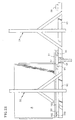
- Fig. 21 is a simplified, stylized side elevation view of a horizontal motion means for use with the invention.
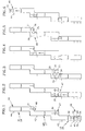
- Figs. 22-28 are simplified, stylized, side elevation views of a shuttle in accordance with a third embodiment of the invention, showing the progress of elevator cabs through the building.
- Figs. 29-43 are simplified, stylized, schematic side elevation views of a shuttle in accordance with a fourth embodiment of the invention, showing the progress of elevator cabs through the building.
- an elevator shuttle comprises a plurality of contiguous, overlapping hoistways including a low hoistway 26, a mid hoistway 27, and a high hoistway 28.
- the low hoistway has a triple deck elevator car frame 29 movable therein
- the mid hoistway has a double deck elevator car 30 movable therein
- the high hoistway has a single deck elevator car movable therein.
- the triple deck car frame 29 has a normal elevator cab 34 fixed thereon.
- the upper two decks of the car frame 29 have movable cabs 35, 36 disposed thereon in Fig. 1.
- the other two car frames 30, 31 are empty.
- the cabs 34-36 receive passengers from related landings 39-41 at the ground level of the building, the destinations of which are to corresponding landings 42-44 at first, second and third upper levels 47-49 of the building, respectively.
- the cab 36 is transferred to the double deck car frame 30 for travel downwardly along with the cab 35 to the second upper level 47, as shown in Fig. 9.
- the cabs 35 and 36 are transferred to the triple deck car frame 29 for travel downwardly with the cab 34 to the ground level 42 as shown in Fig. 11, thereby completing a full, round trip run of the shuttle.
- Figs. 1-11 provides plural elevator cabs serving an equal number of upper levels of the building from the ground level, while only utilizing at the lowest level the core space required for a single elevator hoistway. If desired, the cab 34 could also be movable, to serve other purposes of any sort.
- references to Figs. 3-9 indicate that the triple deck car frame 29 along with its cab 34 waits, for the other cabs to travel upwardly, exchange passengers, and return to the first upper level 47, an amount of time equal to the time required for the events depicted in Figs. 3-9.
- reference to Figs. 5-7 indicate that the double deck car frame 29 waits at the second upper level 48 with its cab 35 for the length of time necessary for the cab 34 to travel to the uppermost level 49 and then return to the second upper level 48, an amount of time equal to the time required for the events depicted in Figs. 5-7.
- a plurality of overlapping, contiguous elevator hoistways include a low hoistway 51, a mid hoistway 52, and a high hoistway 53. Service is provided between a ground level 54 and first, second and third upper levels 55-57.
- service is provided between a lower landing 60 at the ground level and a lower landing 61 at the first upper level; between a landing 62 at the ground level and an upper landing 63 at the first upper level; a mid landing 64 at the ground level and a lower landing 65 at the second upper level; between a mid landing 66 and an upper landing 67 at the second upper level; between an upper landing 68 at the ground level and a lower landing 69 at the third upper level; and between a landing 70 at the ground level and an upper landing 71 at the third upper level.
- the low hoistway 51 and the mid hoistway 52 each have a four deck car frame 75, 76 therein, and the high hoistway 53 has a triple deck car frame 77 therein.
- the three-hoistway embodiment of Figs. 12-20 there are a total of two cabs for each level including the ground level. At any point in time, half of the cabs are in the car frames and half of the cabs are on landings.
- the cabs are denoted simply by capital letters, which represent movable cabs such as cabs 35 and 36 in Figs. 1-11.
- the car frames 75 and 77 have just completed an upward run, and the car frame 76 has just completed a downward run.
- the car frames 75 and 76 always reach the same position at the first upper level 55, but the car frames 76 and 77 land at different positions at the second and third upper levels 56, 57, as is described more fully hereinafter.
- transfers to the left are made in the upper two decks of the car frames 75 and 76, along with the upper landing 63 and transfers to the right are made between the lower decks of the car frames 75, 76 along with the landing 61.
- cabs are exchanged between the car frame 77 and the landings 69, 71 at the third upper level.
- the car frames 75 and 77 each complete a down run, and the car frame 76 completes an up run.
- each of the car frames 75-77 has been stopped at a particular position which differs from run to run for the car frames at the ground level 54 and the second upper level 56.
- the car frame 75 has been stopped in an upper position at the ground level;
- the car frame 76 is stopped in a lower position at the second upper level, which is two decks lower than its other position; and
- the car frame 77 is stopped in an upper position at the second upper level which is one deck higher than another position than it can stop in.
- cabs are exchanged at the second upper level and at the ground level.
- the car frames 75, 76 once again become aligned at the first lower level, and the car frame 77 stops at a low position at the third upper level 57.
- cabs are exchanged at the first upper level 55 and the third upper level 57.
- the car frame 75 travels to a low position at the ground level 54, the car frame 76 goes to a high position at the second upper level 56 and the car frame 77 goes to a low position at the second upper level.
- cabs are exchanged at the ground level 54 and at the second upper level 56.
- the conditions are the same as in Fig. 12 except that different specific cars are in the various positions.
- Fig. 12 and Fig. 9 The pattern between Fig. 12 and Fig. 9 takes eight cycles, and then repeats as is seen by comparison of Figs. 12 and 20, except for the cabs being in different spots. In fact, in 24 cycles, the cabs will return to the same landings. As an example, cab A will go from landing 60 to landing 61, and then back down to landing 70; then it will go to landing 71 and return to landing 64; then it will go to landing 65 and return to landing 60. In each case, the cab travels from the ground level 54 to one of the first, second or third upper levels, and then back to the ground level 54. Therefore, the trip for each cab represents a shuttle trip to a particular one of the upper levels, with no hall stops in between.
- Figs. 12-20 moves three cabs up and down in the lowest hoistway, two cabs in the next higher hoistway, and one cab in the highest hoistway, as does the embodiment of Figs. 1-11.
- the same service is provided to all three levels since there are three cabs moving toward or away from the third highest level, two cabs moving toward or away from the second highest level, and one cab moving toward or away from the first upper level. Therefore, there will be the same number of cabs per unit of time arriving and departing on each of the upper levels, in both embodiments.
- each movable elevator cab will be locked down to the car frame in which it is riding by cab/car locks, which may be of the type disclosed in EP0776858. It is also assumed that each elevator cab will be locked to the building before cabs are moved from the car frame. This is particularly important in the embodiment of Figs. 1-11 where the load on the car frame will change significantly as a result of moving a cab onto or off of the car frame. Locks of this type are disclosed in EP0776859. Simultaneous transfer between car frames and landings, and synchronizing controls to perfect the same, are fully disclosed in EP0781724.
- Fig. 21 illustrates horizontal motive means for moving the cabs between car frames and between landings and car frames, as it may appertain to Fig. 13. This is shown more fully in EPA96308657.4.
- the bottom of the cab A has a fixed, main rack 90 extending from front to back (right to left in Fig. 21), and a sliding auxiliary rack 91 that can slide outwardly to the right, as shown, or to the left.
- an auxiliary motorized pinion 95 turns clockwise to drive the sliding auxiliary rack 91 out from under the cab into the position shown, where it can engage an auxiliary motorized pinion 96 on the platform 93, which is the limit that the rack 91 can slide. Then, the auxiliary motorized pinion 96 will turn clockwise pulling the auxiliary rack 91 (which now is extended to its limit) and therefore the entire cab A to the right as seen in Fig. 21, over a sill 94, until such time as an end 97 of the main rack 90 engages a main motorized pinion (not shown) which is located just behind the auxiliary motorized pinion 96 in Fig. 21.
- auxiliary motorized pinion 99 can assist in moving the cab A to the right onto the landing 60.
- auxiliary pinion 100 similar to pinion 96, could assist in moving a cab from the car frame 76 onto the landing 65.
- the auxiliary pinion 96 will operate counterclockwise, causing the sliding auxiliary rack 91 to move outwardly to the left until its left end 101 engages the auxiliary pinion 95. Then the auxiliary pinion 95 pulls the auxiliary rack 91 and the entire cab A to the left until the left end 102 of the main rack engages a main motorized pinion (not shown) located behind the auxiliary motorized pinion 95, which then pulls the entire cab A to the left until it is fully on the frame 55.
- the high hoistway 28 may be disposed above the low hoistway 26 and the landings 39-41 and 44 might be on the other side of the hoistways from that shown.
- the cabs at the ground level might have been placed in landings opposite to those shown.
- the landings 69 and 71 might be on the opposite sides of the hoistway from that shown, or there may be one landing on each side of the high hoistway 53.
- the high hoistway 53 need not necessarily be over the low hoistway 51, provided the landings 65, 67 are moved to the opposite side of the mid hoistway 52. All of this is totally irrelevant to the present invention.
- Figs. 12-20 only the service to landings 65 and 67 at the second upper level is reachable from the same floor of the ground level (the second floor), at landings 64 and 66.
- the first upper level landings 61, 63 are reached either from the first floor landing 60 on the left of the hoistway or the third floor landing 62 on the right of the hoistway.
- the landings 69, 71 at the third upper level are reached either from the landing 68 which is on the third floor to the right of the hoistway or from landing 70 which is on the first floor to the left of the hoistway. In some installations, this may not be an acceptable boarding pattern.
- the upper two decks of the car frame 75 may have cabs relating to either the second upper level or the third upper level, and the low two decks of the car frame 75 may have cabs relating to either the first upper level or the second upper level. This can be overcome by use of car frames having additional decks.
- Figs. 22-28 only two hoistways 103, 104 are used.
- all service to a second upper level 105 is provided from landings 106, 107 on the right side of the hoistway at the third and fourth floors; all service to a first upper level 108 is provided by landings 109, 110 at the right side of the elevator on the first and second floors.
- This is accomplished by always keeping the cabs related to the second upper level 105 above the cabs related to the first upper level 108 by means of a five deck elevator car frame 111. In each case, there is an empty deck between the cab-carrying decks. Operation of the embodiment of Figs. 22-28, being evident in the light of the description of Figs. 12-20 hereinbefore, is not described further.
- Figs. 29-43 utilizes three hoistways 120-122 to serve a first upper level 123, a second upper level 124, and a third upper level 125 from a ground level 126.
- the car frame 130 in the lowest hoistway 120 requires only a single extra deck
- the car frame 131 in the highest hoistway 122 requires two extra decks
- the car frame 132 in the middle hoistway 121 requires three extra decks, in order to ensure that the cabs are always in the same vertical order in the car frame 130, which is the second upper level on top, the first upper level in the middle, and the third upper level on the bottom.
- Cabs related to the first upper level must be in the middle because the cabs at the first upper level are exchanged alternatively with those at the second upper level and with those at the third upper level.
- This arrangement results in all departures for the second upper level being from the third floor, although on both sides of the hoistway, all departures for the first upper level being on the second floor, and all departures for the third upper level being on the first floor.
- the floor utilized to service the second and third upper levels can be reversed, simply by having the elevator car frame 32 service the second upper level with the lowest three decks thereof, rather than with the highest three decks thereof, and having the car frame 131 align itself with the upper decks of the car frame 132, rather than with the lower decks thereof.
- the landings at the highest level in the embodiments of Figs. 22-28 and of Figs. 29-43 may be on a single floor, on opposite sides of a hoistway. Further, the embodiments of Figs. 22-28 may have the landings disposed on only two floors, on opposite sides of the hoistway, but service for either of the upper levels will consistently be from the same, single floor at the lowest level. In the embodiment of Figs. 29-43, all of the landings at the lowest level may be on the same side of the hoistway, if desired, however, that will require six floors of landings and a seven-deck car frame for the lowest hoistway.
Landscapes
- Engineering & Computer Science (AREA)
- Automation & Control Theory (AREA)
- Structural Engineering (AREA)
- Civil Engineering (AREA)
- Mechanical Engineering (AREA)
- Elevator Control (AREA)
- Types And Forms Of Lifts (AREA)
- Cage And Drive Apparatuses For Elevators (AREA)
Applications Claiming Priority (4)
| Application Number | Priority Date | Filing Date | Title |
|---|---|---|---|
| US68486796A | 1996-07-25 | 1996-07-25 | |
| US684867 | 1996-07-25 | ||
| US08/751,797 US5924524A (en) | 1996-07-25 | 1996-11-18 | Integrated, multi-level elevator shuttle |
| US751797 | 1996-11-18 |
Publications (2)
| Publication Number | Publication Date |
|---|---|
| EP0820952A2 true EP0820952A2 (fr) | 1998-01-28 |
| EP0820952A3 EP0820952A3 (fr) | 1998-04-01 |
Family
ID=27103449
Family Applications (1)
| Application Number | Title | Priority Date | Filing Date |
|---|---|---|---|
| EP97305588A Withdrawn EP0820952A3 (fr) | 1996-07-25 | 1997-07-25 | Méthode de répartition des cabines entre des navettes d'ascenseurs avec plateformes à plusieurs niveaux pour cabines |
Country Status (6)
| Country | Link |
|---|---|
| US (1) | US5924524A (fr) |
| EP (1) | EP0820952A3 (fr) |
| JP (1) | JPH10114471A (fr) |
| KR (1) | KR980009082A (fr) |
| CN (1) | CN1172763A (fr) |
| ID (1) | ID17614A (fr) |
Cited By (4)
| Publication number | Priority date | Publication date | Assignee | Title |
|---|---|---|---|---|
| US7360629B2 (en) | 2003-10-09 | 2008-04-22 | Inventio Ag | Zonally operated elevator installation and method |
| US7537089B2 (en) | 2004-07-22 | 2009-05-26 | Inventio Ag | Elevator installation with individually movable elevator cars and method for operating such an elevator installation |
| EP1851155A4 (fr) * | 2005-02-04 | 2010-09-01 | Otis Elevator Co | Appels attribues a l'une des deux cabines presentes dans une cage d'ascenseur pour minimiser le retard impose a l'une ou l'autre des cabines |
| US20210139282A1 (en) * | 2017-05-11 | 2021-05-13 | Thyssenkrupp Elevator Innovation And Operations Gmbh | Elevator system having two shafts |
Families Citing this family (16)
| Publication number | Priority date | Publication date | Assignee | Title |
|---|---|---|---|---|
| JP2004002020A (ja) * | 2002-05-27 | 2004-01-08 | Inventio Ag | 数台の自走式かごと少なくとも3つの隣接配置されたエレベータ昇降路とを備えたエレベータ設備 |
| JP2006027902A (ja) * | 2004-07-15 | 2006-02-02 | Inventio Ag | 互いに隣接して配置される少なくとも3つの垂直エレベータ昇降路を有するエレベータ設備およびそのようなエレベータ昇降路の動作方法 |
| US7841450B2 (en) | 2005-08-19 | 2010-11-30 | Thyssenkrupp Elevator Capital Corporation | Twin elevator systems |
| WO2007133173A2 (fr) * | 2006-04-11 | 2007-11-22 | Otis Elevator Company | Système d'ascenseurs comprenant un transfert de passagers de cabine à cabine |
| IL184194A (en) * | 2006-07-25 | 2012-02-29 | Inventio Ag | Method of modernizing a lift installation |
| US7913818B2 (en) * | 2006-12-22 | 2011-03-29 | Inventio Ag | Elevator installation in a building with at least one transfer floor |
| MY149246A (en) * | 2006-12-22 | 2013-07-31 | Inventio Ag | Elevator installation in a building with at least one transfer floor |
| ES2536799B1 (es) * | 2013-11-28 | 2016-03-04 | Fernando Antolín García | Sistema optimizado de transporte en ascensor en edificios de gran altura |
| DE102014201804A1 (de) * | 2014-01-31 | 2015-08-06 | Thyssenkrupp Elevator Ag | Verfahren zum Betreiben eines Aufzugsystems |
| US10017354B2 (en) * | 2015-07-10 | 2018-07-10 | Otis Elevator Company | Control system for multicar elevator system |
| US10865072B2 (en) * | 2015-08-03 | 2020-12-15 | Otis Elevator Company | Intermediate transfer station |
| AU2016231585B2 (en) | 2015-09-25 | 2018-08-09 | Otis Elevator Company | Elevator component separation assurance system and method of operation |
| US9598265B1 (en) | 2015-09-28 | 2017-03-21 | Smart Lifts, Llc | Vertically and horizontally mobile elevator cabins |
| US10966936B2 (en) | 2015-12-30 | 2021-04-06 | Corium, Inc. | Systems comprising a composite backing and methods for long term transdermal administration |
| US10081513B2 (en) * | 2016-12-09 | 2018-09-25 | Otis Elevator Company | Motion profile for empty elevator cars and occupied elevator cars |
| WO2019226084A1 (fr) * | 2018-05-22 | 2019-11-28 | Saab Ab | Système de transport vertical actionné par un agencement d'actionneur linéaire hydraulique |
Family Cites Families (2)
| Publication number | Priority date | Publication date | Assignee | Title |
|---|---|---|---|---|
| US1939729A (en) * | 1930-01-29 | 1933-12-19 | Thomas W Cohill | Elevator system |
| US5419414A (en) * | 1993-11-18 | 1995-05-30 | Sakita; Masami | Elevator system with multiple cars in the same hoistway |
-
1996
- 1996-11-18 US US08/751,797 patent/US5924524A/en not_active Expired - Fee Related
-
1997
- 1997-07-24 CN CN97104670A patent/CN1172763A/zh active Pending
- 1997-07-25 ID IDP972589A patent/ID17614A/id unknown
- 1997-07-25 EP EP97305588A patent/EP0820952A3/fr not_active Withdrawn
- 1997-07-25 JP JP9199572A patent/JPH10114471A/ja not_active Withdrawn
- 1997-07-25 KR KR1019970034938A patent/KR980009082A/ko not_active Withdrawn
Cited By (5)
| Publication number | Priority date | Publication date | Assignee | Title |
|---|---|---|---|---|
| US7360629B2 (en) | 2003-10-09 | 2008-04-22 | Inventio Ag | Zonally operated elevator installation and method |
| US7537089B2 (en) | 2004-07-22 | 2009-05-26 | Inventio Ag | Elevator installation with individually movable elevator cars and method for operating such an elevator installation |
| EP1851155A4 (fr) * | 2005-02-04 | 2010-09-01 | Otis Elevator Co | Appels attribues a l'une des deux cabines presentes dans une cage d'ascenseur pour minimiser le retard impose a l'une ou l'autre des cabines |
| US20210139282A1 (en) * | 2017-05-11 | 2021-05-13 | Thyssenkrupp Elevator Innovation And Operations Gmbh | Elevator system having two shafts |
| US12479700B2 (en) * | 2017-05-11 | 2025-11-25 | Tk Elevator Innovation And Operations Gmbh | Elevator system having two shafts |
Also Published As
| Publication number | Publication date |
|---|---|
| EP0820952A3 (fr) | 1998-04-01 |
| JPH10114471A (ja) | 1998-05-06 |
| CN1172763A (zh) | 1998-02-11 |
| US5924524A (en) | 1999-07-20 |
| KR980009082A (ko) | 1998-04-30 |
| ID17614A (id) | 1998-01-15 |
Similar Documents
| Publication | Publication Date | Title |
|---|---|---|
| US5924524A (en) | Integrated, multi-level elevator shuttle | |
| TWI343357B (en) | Elevator installation with individually movable elevator cars and method for operating such an elevator installation | |
| FI112350B (fi) | Hissijärjestelmä | |
| US5758748A (en) | Synchronized off-shaft loading of elevator cabs | |
| US20030217893A1 (en) | Elevator installation comprising a number of individually propelled cars in at least three adjacent hoistways | |
| US5823299A (en) | Shuttle elevators feeding local elevators | |
| US5752585A (en) | Elevator shuttle with auxiliary elevators at terminals | |
| JP5986666B1 (ja) | エレベータシステム | |
| FI85576B (fi) | Vertikalt transportsystem i byggnader. | |
| JP4961774B2 (ja) | エレベータシステム | |
| GB2320013A (en) | Elevator shuttle system | |
| Siikonen | Double-Deck Elevators: Savings in time and space | |
| FI118125B (fi) | Hissijärjestelmä | |
| CN202279598U (zh) | 多层电梯 | |
| KR970059064A (ko) | 엑스트라 데크 엘리베이터 셔틀 | |
| HK1008207A (en) | Integrated, multi-level elevator shuttle | |
| Fortune | Modern double deck elevator applications and theory | |
| WO2018042638A1 (fr) | Système d'ascenseur | |
| KR19980032594A (ko) | 운영 모드사이를 변경하는 다수 덱크 엘리베이터 셔틀시스템 및 그 방법 | |
| KR19980032716A (ko) | 일방적 오프 샤프트 로딩을 갖는 엘리베이터 셔틀 | |
| HK1064079B (en) | Elevator system with a plurality of self-moving cabins and at least three parallel shafts | |
| KR980009083A (ko) | 터미널에서 보조 엘리베이터를 가진 엘리베이터 셔틀 | |
| HK1008210A (en) | Elevator shuttle with auxiliary elevators at terminals | |
| HK1006255A (en) | Synchronized off-shaft loading of elevator cabs | |
| JPH05262479A (ja) | 隣接階移動装置とそれを組み込んだ昇降システム |
Legal Events
| Date | Code | Title | Description |
|---|---|---|---|
| PUAI | Public reference made under article 153(3) epc to a published international application that has entered the european phase |
Free format text: ORIGINAL CODE: 0009012 |
|
| AK | Designated contracting states |
Kind code of ref document: A2 Designated state(s): AT BE CH DE DK ES FI FR GB GR IE IT LI LU MC NL PT SE |
|
| AX | Request for extension of the european patent |
Free format text: AL;LT;LV;RO;SI |
|
| PUAL | Search report despatched |
Free format text: ORIGINAL CODE: 0009013 |
|
| AK | Designated contracting states |
Kind code of ref document: A3 Designated state(s): AT BE CH DE DK ES FI FR GB GR IE IT LI LU MC NL PT SE |
|
| AX | Request for extension of the european patent |
Free format text: AL;LT;LV;RO;SI |
|
| 17P | Request for examination filed |
Effective date: 19980507 |
|
| STAA | Information on the status of an ep patent application or granted ep patent |
Free format text: STATUS: THE APPLICATION HAS BEEN WITHDRAWN |
|
| 18W | Application withdrawn |
Withdrawal date: 19980708 |