EP0821146A2 - Kohlenwasserstoff-Adsorptionssystem für Kraftfahrzeug - Google Patents
Kohlenwasserstoff-Adsorptionssystem für Kraftfahrzeug Download PDFInfo
- Publication number
- EP0821146A2 EP0821146A2 EP97110642A EP97110642A EP0821146A2 EP 0821146 A2 EP0821146 A2 EP 0821146A2 EP 97110642 A EP97110642 A EP 97110642A EP 97110642 A EP97110642 A EP 97110642A EP 0821146 A2 EP0821146 A2 EP 0821146A2
- Authority
- EP
- European Patent Office
- Prior art keywords
- adsorber
- channels
- enclosure
- exhaust
- exhaust gas
- Prior art date
- Legal status (The legal status is an assumption and is not a legal conclusion. Google has not performed a legal analysis and makes no representation as to the accuracy of the status listed.)
- Withdrawn
Links
Images

Classifications
-
- F—MECHANICAL ENGINEERING; LIGHTING; HEATING; WEAPONS; BLASTING
- F01—MACHINES OR ENGINES IN GENERAL; ENGINE PLANTS IN GENERAL; STEAM ENGINES
- F01N—GAS-FLOW SILENCERS OR EXHAUST APPARATUS FOR MACHINES OR ENGINES IN GENERAL; GAS-FLOW SILENCERS OR EXHAUST APPARATUS FOR INTERNAL-COMBUSTION ENGINES
- F01N3/00—Exhaust or silencing apparatus having means for purifying, rendering innocuous, or otherwise treating exhaust
- F01N3/08—Exhaust or silencing apparatus having means for purifying, rendering innocuous, or otherwise treating exhaust for rendering innocuous
- F01N3/0807—Exhaust or silencing apparatus having means for purifying, rendering innocuous, or otherwise treating exhaust for rendering innocuous by using absorbents or adsorbents
- F01N3/0828—Exhaust or silencing apparatus having means for purifying, rendering innocuous, or otherwise treating exhaust for rendering innocuous by using absorbents or adsorbents characterised by the absorbed or adsorbed substances
- F01N3/0835—Hydrocarbons
-
- B—PERFORMING OPERATIONS; TRANSPORTING
- B01—PHYSICAL OR CHEMICAL PROCESSES OR APPARATUS IN GENERAL
- B01D—SEPARATION
- B01D53/00—Separation of gases or vapours; Recovering vapours of volatile solvents from gases; Chemical or biological purification of waste gases, e.g. engine exhaust gases, smoke, fumes, flue gases, aerosols
- B01D53/34—Chemical or biological purification of waste gases
- B01D53/92—Chemical or biological purification of waste gases of engine exhaust gases
- B01D53/94—Chemical or biological purification of waste gases of engine exhaust gases by catalytic processes
- B01D53/944—Simultaneously removing carbon monoxide, hydrocarbons or carbon making use of oxidation catalysts
-
- B—PERFORMING OPERATIONS; TRANSPORTING
- B01—PHYSICAL OR CHEMICAL PROCESSES OR APPARATUS IN GENERAL
- B01D—SEPARATION
- B01D53/00—Separation of gases or vapours; Recovering vapours of volatile solvents from gases; Chemical or biological purification of waste gases, e.g. engine exhaust gases, smoke, fumes, flue gases, aerosols
- B01D53/34—Chemical or biological purification of waste gases
- B01D53/92—Chemical or biological purification of waste gases of engine exhaust gases
- B01D53/94—Chemical or biological purification of waste gases of engine exhaust gases by catalytic processes
- B01D53/9481—Catalyst preceded by an adsorption device without catalytic function for temporary storage of contaminants, e.g. during cold start
- B01D53/9486—Catalyst preceded by an adsorption device without catalytic function for temporary storage of contaminants, e.g. during cold start for storing hydrocarbons
-
- F—MECHANICAL ENGINEERING; LIGHTING; HEATING; WEAPONS; BLASTING
- F01—MACHINES OR ENGINES IN GENERAL; ENGINE PLANTS IN GENERAL; STEAM ENGINES
- F01N—GAS-FLOW SILENCERS OR EXHAUST APPARATUS FOR MACHINES OR ENGINES IN GENERAL; GAS-FLOW SILENCERS OR EXHAUST APPARATUS FOR INTERNAL-COMBUSTION ENGINES
- F01N13/00—Exhaust or silencing apparatus characterised by constructional features
- F01N13/009—Exhaust or silencing apparatus characterised by constructional features having two or more separate purifying devices arranged in series
-
- F—MECHANICAL ENGINEERING; LIGHTING; HEATING; WEAPONS; BLASTING
- F01—MACHINES OR ENGINES IN GENERAL; ENGINE PLANTS IN GENERAL; STEAM ENGINES
- F01N—GAS-FLOW SILENCERS OR EXHAUST APPARATUS FOR MACHINES OR ENGINES IN GENERAL; GAS-FLOW SILENCERS OR EXHAUST APPARATUS FOR INTERNAL-COMBUSTION ENGINES
- F01N3/00—Exhaust or silencing apparatus having means for purifying, rendering innocuous, or otherwise treating exhaust
- F01N3/08—Exhaust or silencing apparatus having means for purifying, rendering innocuous, or otherwise treating exhaust for rendering innocuous
- F01N3/0807—Exhaust or silencing apparatus having means for purifying, rendering innocuous, or otherwise treating exhaust for rendering innocuous by using absorbents or adsorbents
- F01N3/0814—Exhaust or silencing apparatus having means for purifying, rendering innocuous, or otherwise treating exhaust for rendering innocuous by using absorbents or adsorbents combined with catalytic converters, e.g. NOx absorption/storage reduction catalysts
-
- F—MECHANICAL ENGINEERING; LIGHTING; HEATING; WEAPONS; BLASTING
- F01—MACHINES OR ENGINES IN GENERAL; ENGINE PLANTS IN GENERAL; STEAM ENGINES
- F01N—GAS-FLOW SILENCERS OR EXHAUST APPARATUS FOR MACHINES OR ENGINES IN GENERAL; GAS-FLOW SILENCERS OR EXHAUST APPARATUS FOR INTERNAL-COMBUSTION ENGINES
- F01N3/00—Exhaust or silencing apparatus having means for purifying, rendering innocuous, or otherwise treating exhaust
- F01N3/08—Exhaust or silencing apparatus having means for purifying, rendering innocuous, or otherwise treating exhaust for rendering innocuous
- F01N3/0807—Exhaust or silencing apparatus having means for purifying, rendering innocuous, or otherwise treating exhaust for rendering innocuous by using absorbents or adsorbents
- F01N3/0871—Exhaust or silencing apparatus having means for purifying, rendering innocuous, or otherwise treating exhaust for rendering innocuous by using absorbents or adsorbents using means for controlling, e.g. purging, the absorbents or adsorbents
- F01N3/0878—Bypassing absorbents or adsorbents
-
- F—MECHANICAL ENGINEERING; LIGHTING; HEATING; WEAPONS; BLASTING
- F01—MACHINES OR ENGINES IN GENERAL; ENGINE PLANTS IN GENERAL; STEAM ENGINES
- F01N—GAS-FLOW SILENCERS OR EXHAUST APPARATUS FOR MACHINES OR ENGINES IN GENERAL; GAS-FLOW SILENCERS OR EXHAUST APPARATUS FOR INTERNAL-COMBUSTION ENGINES
- F01N3/00—Exhaust or silencing apparatus having means for purifying, rendering innocuous, or otherwise treating exhaust
- F01N3/08—Exhaust or silencing apparatus having means for purifying, rendering innocuous, or otherwise treating exhaust for rendering innocuous
- F01N3/10—Exhaust or silencing apparatus having means for purifying, rendering innocuous, or otherwise treating exhaust for rendering innocuous by thermal or catalytic conversion of noxious components of exhaust
- F01N3/18—Exhaust or silencing apparatus having means for purifying, rendering innocuous, or otherwise treating exhaust for rendering innocuous by thermal or catalytic conversion of noxious components of exhaust characterised by methods of operation; Control
- F01N3/20—Exhaust or silencing apparatus having means for purifying, rendering innocuous, or otherwise treating exhaust for rendering innocuous by thermal or catalytic conversion of noxious components of exhaust characterised by methods of operation; Control specially adapted for catalytic conversion
- F01N3/2006—Periodically heating or cooling catalytic reactors, e.g. at cold starting or overheating
-
- F—MECHANICAL ENGINEERING; LIGHTING; HEATING; WEAPONS; BLASTING
- F01—MACHINES OR ENGINES IN GENERAL; ENGINE PLANTS IN GENERAL; STEAM ENGINES
- F01N—GAS-FLOW SILENCERS OR EXHAUST APPARATUS FOR MACHINES OR ENGINES IN GENERAL; GAS-FLOW SILENCERS OR EXHAUST APPARATUS FOR INTERNAL-COMBUSTION ENGINES
- F01N3/00—Exhaust or silencing apparatus having means for purifying, rendering innocuous, or otherwise treating exhaust
- F01N3/08—Exhaust or silencing apparatus having means for purifying, rendering innocuous, or otherwise treating exhaust for rendering innocuous
- F01N3/10—Exhaust or silencing apparatus having means for purifying, rendering innocuous, or otherwise treating exhaust for rendering innocuous by thermal or catalytic conversion of noxious components of exhaust
- F01N3/24—Exhaust or silencing apparatus having means for purifying, rendering innocuous, or otherwise treating exhaust for rendering innocuous by thermal or catalytic conversion of noxious components of exhaust characterised by constructional aspects of converting apparatus
- F01N3/28—Construction of catalytic reactors
- F01N3/2892—Exhaust flow directors or the like, e.g. upstream of catalytic device
-
- F—MECHANICAL ENGINEERING; LIGHTING; HEATING; WEAPONS; BLASTING
- F01—MACHINES OR ENGINES IN GENERAL; ENGINE PLANTS IN GENERAL; STEAM ENGINES
- F01N—GAS-FLOW SILENCERS OR EXHAUST APPARATUS FOR MACHINES OR ENGINES IN GENERAL; GAS-FLOW SILENCERS OR EXHAUST APPARATUS FOR INTERNAL-COMBUSTION ENGINES
- F01N3/00—Exhaust or silencing apparatus having means for purifying, rendering innocuous, or otherwise treating exhaust
- F01N3/08—Exhaust or silencing apparatus having means for purifying, rendering innocuous, or otherwise treating exhaust for rendering innocuous
- F01N3/10—Exhaust or silencing apparatus having means for purifying, rendering innocuous, or otherwise treating exhaust for rendering innocuous by thermal or catalytic conversion of noxious components of exhaust
- F01N3/24—Exhaust or silencing apparatus having means for purifying, rendering innocuous, or otherwise treating exhaust for rendering innocuous by thermal or catalytic conversion of noxious components of exhaust characterised by constructional aspects of converting apparatus
- F01N3/30—Arrangements for supply of additional air
- F01N3/32—Arrangements for supply of additional air using air pump
- F01N3/323—Electrically driven air pumps
-
- F—MECHANICAL ENGINEERING; LIGHTING; HEATING; WEAPONS; BLASTING
- F01—MACHINES OR ENGINES IN GENERAL; ENGINE PLANTS IN GENERAL; STEAM ENGINES
- F01N—GAS-FLOW SILENCERS OR EXHAUST APPARATUS FOR MACHINES OR ENGINES IN GENERAL; GAS-FLOW SILENCERS OR EXHAUST APPARATUS FOR INTERNAL-COMBUSTION ENGINES
- F01N2240/00—Combination or association of two or more different exhaust treating devices, or of at least one such device with an auxiliary device, not covered by indexing codes F01N2230/00 or F01N2250/00, one of the devices being
- F01N2240/20—Combination or association of two or more different exhaust treating devices, or of at least one such device with an auxiliary device, not covered by indexing codes F01N2230/00 or F01N2250/00, one of the devices being a flow director or deflector
-
- F—MECHANICAL ENGINEERING; LIGHTING; HEATING; WEAPONS; BLASTING
- F01—MACHINES OR ENGINES IN GENERAL; ENGINE PLANTS IN GENERAL; STEAM ENGINES
- F01N—GAS-FLOW SILENCERS OR EXHAUST APPARATUS FOR MACHINES OR ENGINES IN GENERAL; GAS-FLOW SILENCERS OR EXHAUST APPARATUS FOR INTERNAL-COMBUSTION ENGINES
- F01N2250/00—Combinations of different methods of purification
- F01N2250/12—Combinations of different methods of purification absorption or adsorption, and catalytic conversion
-
- F—MECHANICAL ENGINEERING; LIGHTING; HEATING; WEAPONS; BLASTING
- F01—MACHINES OR ENGINES IN GENERAL; ENGINE PLANTS IN GENERAL; STEAM ENGINES
- F01N—GAS-FLOW SILENCERS OR EXHAUST APPARATUS FOR MACHINES OR ENGINES IN GENERAL; GAS-FLOW SILENCERS OR EXHAUST APPARATUS FOR INTERNAL-COMBUSTION ENGINES
- F01N2410/00—By-passing, at least partially, exhaust from inlet to outlet of apparatus, to atmosphere or to other device
- F01N2410/12—By-passing, at least partially, exhaust from inlet to outlet of apparatus, to atmosphere or to other device in case of absorption, adsorption or desorption of exhaust gas constituents
-
- F—MECHANICAL ENGINEERING; LIGHTING; HEATING; WEAPONS; BLASTING
- F01—MACHINES OR ENGINES IN GENERAL; ENGINE PLANTS IN GENERAL; STEAM ENGINES
- F01N—GAS-FLOW SILENCERS OR EXHAUST APPARATUS FOR MACHINES OR ENGINES IN GENERAL; GAS-FLOW SILENCERS OR EXHAUST APPARATUS FOR INTERNAL-COMBUSTION ENGINES
- F01N3/00—Exhaust or silencing apparatus having means for purifying, rendering innocuous, or otherwise treating exhaust
- F01N3/08—Exhaust or silencing apparatus having means for purifying, rendering innocuous, or otherwise treating exhaust for rendering innocuous
- F01N3/10—Exhaust or silencing apparatus having means for purifying, rendering innocuous, or otherwise treating exhaust for rendering innocuous by thermal or catalytic conversion of noxious components of exhaust
- F01N3/24—Exhaust or silencing apparatus having means for purifying, rendering innocuous, or otherwise treating exhaust for rendering innocuous by thermal or catalytic conversion of noxious components of exhaust characterised by constructional aspects of converting apparatus
- F01N3/30—Arrangements for supply of additional air
- F01N3/32—Arrangements for supply of additional air using air pump
-
- Y—GENERAL TAGGING OF NEW TECHNOLOGICAL DEVELOPMENTS; GENERAL TAGGING OF CROSS-SECTIONAL TECHNOLOGIES SPANNING OVER SEVERAL SECTIONS OF THE IPC; TECHNICAL SUBJECTS COVERED BY FORMER USPC CROSS-REFERENCE ART COLLECTIONS [XRACs] AND DIGESTS
- Y02—TECHNOLOGIES OR APPLICATIONS FOR MITIGATION OR ADAPTATION AGAINST CLIMATE CHANGE
- Y02A—TECHNOLOGIES FOR ADAPTATION TO CLIMATE CHANGE
- Y02A50/00—TECHNOLOGIES FOR ADAPTATION TO CLIMATE CHANGE in human health protection, e.g. against extreme weather
- Y02A50/20—Air quality improvement or preservation, e.g. vehicle emission control or emission reduction by using catalytic converters
-
- Y—GENERAL TAGGING OF NEW TECHNOLOGICAL DEVELOPMENTS; GENERAL TAGGING OF CROSS-SECTIONAL TECHNOLOGIES SPANNING OVER SEVERAL SECTIONS OF THE IPC; TECHNICAL SUBJECTS COVERED BY FORMER USPC CROSS-REFERENCE ART COLLECTIONS [XRACs] AND DIGESTS
- Y02—TECHNOLOGIES OR APPLICATIONS FOR MITIGATION OR ADAPTATION AGAINST CLIMATE CHANGE
- Y02T—CLIMATE CHANGE MITIGATION TECHNOLOGIES RELATED TO TRANSPORTATION
- Y02T10/00—Road transport of goods or passengers
- Y02T10/10—Internal combustion engine [ICE] based vehicles
- Y02T10/12—Improving ICE efficiencies
Definitions
- Tightened emissions standards for automotive gasoline engines have placed higher demands on the performance of these catalytic conversion systems.
- Particularly critical for overall system performance is performance during the so-called "cold start” phase of engine operation. This is the period of engine operation just after cold engine start and prior to startup or “light off” of the catalytic converter, during which the highest concentrations of unburned hydrocarbons are released into the atmosphere.
- One type of exhaust system designed specifically to address the cold-start problem, provides a hydrocarbon (e.g., unburned fuel and combustion by-products) adsorber in the exhaust line.
- the adsorber operates to trap the hydrocarbons emitted, particularly at engine startup, and then to release the hydrocarbons to the catalytic converter after converter light-off has been achieved.
- a preferred configuration for an adsorber in such systems is a honeycomb similar in structure to a catalyst support honeycomb but composed of or supporting a coating of a hydrocarbon adsorbent such as carbon, zeolite, or another molecular sieve material.
- a common feature of these systems is a ported adsorber, e.g., an adsorber incorporating an integral by-pass port within the body of its structure. Typically located downstream of a first catalytic converter, this adsorber is positioned upstream of a second or so-called "burn-off" catalytic converter so that hydrocarbons trapped by the adsorber at engine startup can subsequently be desorbed and released to the downstream converter as the adsorber is heated by the warning exhaust gases.
- a particular advantage of the ported adsorber design is the faster light-off of the downstream catalytic converter, due to exposure of that converter to the high-velocity exhaust gases passing through the adsorber port.
- control over the flow of the exhaust gases through the adsorber is obtained by means of a fluidic diverter which delivers a control gas stream for diverting the exhaust gases toward or away from the adsorber port in the course of engine operation.
- the invention provides an improved system for the treatment of combustion engine exhaust gases, based on an improved adsorber design for ported adsorber systems such as above described. More particularly, the invention comprises an improvement in exhaust systems of the type wherein an exhaust conduit supplies exhaust gas to an adsorber mounted in a enclosure downstream of a engine, wherein the adsorber comprises a honeycomb having a plurality of channels with hydrocarbon-adsorbing walls running from its inlet face to its outlet face and incorporating a integral by-pass port for the transmission of exhaust gas past the adsorbing channels.
- these systems include a catalytic converter mounted downstream of the adsorber, and a diverter line having an outlet within the adsorber enclosure and upstream of the adsorber by-pass port for delivering at the port a diversion fluid such as air from a source external to the enclosure.
- the diverter provided in these systems acts mainly to direct the flow of exhaust gases away from the by-pass port and through the honeycomb channels for effective hydrocarbon adsorption during the early or cold-start phase of engine operation.
- the exhaust system of the invention employs an improved adsorber design wherein the honeycomb structure has central and peripheral portions of differing flow characteristics. Traversing the central portion of the honeycomb, in addition to the by-pass port, is a first plurality of channels having a relatively high resistance to exhaust gas flow. A second plurality of channels, traversing the peripheral portion of the honeycomb adsorber, has a relatively low resistance to exhaust gas flow.
- the honeycomb adsorber comprises a inlet face and/or a outlet face of generally convex configuration.
- the purpose of this inlet and/or outlet face design is to insure that the first plurality of honeycomb channels, i.e., those proximate to the by-pass port, are of longer average length than the second plurality of honeycomb channels proximate to the periphery of the honeycomb.
- Any of a number of different face configurations including but not limited to frustoconical, stepped, or smoothly curved to circular, parabolic, or elliptical profiles could be used to achieve the desired effect.
- the resulting differences in channel length modify the flow resistance and thus the gas flow velocities through the channels, so as to make flow velocities through the peripheral channels more closely match the gas flow velocities through the more central channels.
- the efficiency of the burn-off converter is further improved by promoting mixing of the exhaust gases immediately upstream of the converter.
- a mixing plate disposed between the adsorber and the burn-off converter acts to promote more uniform pre-heating of the burn-off converter as well as better distribution across the converter of hydrocarbon effluents released by the adsorber.
- FIG. 1 of the drawing presents a schematic elevational cross-section of a typical system design, not in true proportion or to scale.
- exhaust gas flowing from a engine (not shown) in the direction of arrow 10 enters enclosure 12 through exhaust conduit 14.
- an adsorber 16 Disposed within enclosure 12 is an adsorber 16, that adsorber comprising a honeycomb having a plurality of cells or through-channels 18 through which the exhaust gases may pass.
- Adsorber 16 also features a by-pass port 20, consisting of a central hole through the honeycomb, through which exhaust gases may flow to by-pass channels 18 and impinge more directly on catalytic converter 22 located downstream of adsorber 16.
- a diverter line 24 for supplying a diversion fluid such as secondary air from an external fluid source such as a air pump (not shown) is provided.
- the outlet 26 of the diverter line is positioned proximate to and upstream of by-pass port 20.
- adsorber 16 is provided with a tapered, convexly shaped inlet face 27 for the exhaust gas.
- the shape of inlet face 27 effects a relative shortening of channels 18 located at peripheral portions of adsorber 16 (i.e., portions near the wall of enclosure 12) with respect to channels located centrally and proximate to by-pass port 20.
- components which may be provided in conjunction with the improved adsorber as shown in Fig. 1 of the drawing include sensor 28 for determining the concentrations of hydrocarbons or other species present in the exhaust, and secondary air inlets such as air injector port 30 for controlling the stoichiometry of the gases being treated.
- the inlet face of catalytic converter 32 may be convexly configured in order to make the exhaust gas velocities through the channels of that converter more uniform.
- an optional flow-converging inlet cone may be provided immediately upstream of the adsorber to shape and direct the exhaust gas stream more effectively into the adsorber port.
- exhaust gases from the engine which are supplied to adsorber 16 through exhaust conduit 14 are initially diverted away from by-pass port 20 and through honeycomb channels 18 by introducing a stream of diversion fluid (e.g. secondary air) through line 24 and outlet 26 at engine startup.
- a stream of diversion fluid e.g. secondary air
- the flow of exhaust gases carrying the unburned or partially burned hydrocarbons through channels 18 of the adsorber is rendered more uniform. That is, gas flow velocities through the channels proximate to the honeycomb periphery are increased to more closely approximate the reduced gas flow velocities through the channels proximate to the center port.
- the advantages of a system incorporating this adsorber design are two-fold. First, the effectiveness of the adsorber is improved since the adsorption capacity of the honeycomb channels near the honeycomb periphery is more fully utilized. Secondly, the life of the adsorber can be extended since the reduced exhaust flows through the honeycomb channels proximate to the by-pass channels during hot engine operation reduce the service temperatures to which those portions of the adsorber honeycomb must be subjected in use.
- Convex shapes which may be considered for use in the invention include conical or frustoconical shapes as well as shapes which are stepped or smoothly curved to circular, parabolic, or elliptical profiles. Combinations of various curves and facets may also be used.
- tapered inlet face design for the catalytic converter disposed downstream of the adsorber honeycomb, as well as for any light-off or main underbody catalytic converters located upstream of the adsorber.
- tapered inlet designs for these converters can help to me the flow of exhaust gases more uniform through the channels of these honeycombs as well, by tending to equalize channel exhaust gas flow velocity through peripheral channels with that through centrally disposed channels.
- An alternative design for an adsorber provided in accordance with the invention is a design where the average hydraulic diameter of the first plurality of honeycomb channels proximate to the by-pass port is smaller than the average hydraulic diameter of the second plurality of honeycomb channels proximate to the periphery of the honeycomb.
- An example of such an adsorber is schematically illustrated in Fig. 2 of the drawing, which is an end view of the inlet face of an adsorber honeycomb of this type.
- the first plurality of honeycomb channels in region 18a of the honeycomb inlet face are of smaller size than the second plurality of honeycomb channels in region 18b of that face.
- the average hydraulic diameter of channels 18b is higher than that of channels 18a, and the exhaust gas flow velocities through the latter channels is correspondingly reduced.
- additional catalytic converters may be provided downstream or, more commonly, upstream of the adsorber system shown in Fig. 1.
- the main catalytic converter for the engine which may be a main catalyst or a pre-catalyst, is typically located upstream of the adsorber enclosure for more rapid light-off
- the adsorber and burn-off (downstream) converter then function principally to trap and later oxidize hydrocarbons passing through the main catalytic converter during the cold-start phase of engine operation.
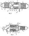
- An example of an exhaust emissions control system of this type, but incorporating an improved adsorber in accordance with the invention, is shown in Fig. 3 of the drawing.
- one concern of systems designers adapting these cold-start systems to production vehicles is the complexity of the secondary air sub-systems required to control exhaust stream stoichiometry through the various stages of the emissions control process.
- Currently developing adaptations of adsorber-based cold-start systems such as described in the above patent publications typically comprise an upstream catalyst stage (a large main catalyst or pre-catalyst), an adsorber stage, and a downstream or burn-off catalyst stage.
- Ports for the injection of secondary air in these systems are usually provided at or upstream of the entrances to each of these stages, either to control gas stream stoichiometry or, in the case of the adsorber of EP 0697505, to control the path of the gas stream.
- These multiple air injection ports can necessitate the use of multiple air delivery systems, including separate air pumps, air delivery lines, and air flow control systems, in order to deliver the volumes of air to the various stages which have been thought to be required.
- the primary or sole means for injecting secondary air into the adsorber section of the exhaust system of the invention which is also the means for controlling the flow of exhaust gases through the adsorber, is diverter line 24 connecting with an external air source and terminating at outlet 26 within the adsorber enclosure section.
- Other sources of secondary air are merely optional.
- exhaust gas flowing from an engine (not shown) into enclosure section 2 through exhaust conduit 14 in the downstream direction of arrow 10 passes initially through a first catalytic converter 8.
- a secondary air inlet for providing "main" secondary air is normally provided upstream of catalytic converter 8 to control oxygen levels in the exhaust gas being reacted in converter 8, although in the present system such an inlet is optional.
- Adsorber 16 After traversing first converter 8 the exhaust gas passes into enclosure section 12 within which is disposed tapered adsorber 16, that adsorber consisting of a honeycomb having a tapered inlet face 27 and incorporating a plurality of through-channels 18 through which the exhaust gases may pass to adsorb unburned hydrocarbons contained therein.
- Adsorber 16 also includes a by-pass port 20 through which the exhaust gases can by-pass channels 18 to impinge more directly on burn-off converter 22 located in an enclosure 23 downstream of adsorber 16.
- diverter line 24 entering enclosure section 12 operates not only to control the flow of exhaust gases through or away from port 20, but also serves as the sole or primary means for injecting secondary air into the system, that secondary air being delivered from an external air source such as an air pump (not shown).
- Outlet 26 of diverter line 24 is positioned proximate to and upstream of by-pass port 20, being provided in this embodiment with a diverter or deflector body 29 configured to pattern the stream of secondary air most effectively to divert the exhaust gas stream away from by-pass port 20 and through channels 18 of the adsorber.
- an optional exhaust gas flow concentrator or collector in this case consisting of open-ended convergent cone 11. That cone, joined at its larger end to the wall of adsorber enclosure section 12 upstream of the adsorber, functions to collect exhaust gases exiting first converter 8 and channel them more directly and effectively toward port 20.
- diverter line 24 as the primary means for injecting secondary air in accordance with the invention means that diverter air will supply at least 60% of all secondary air required by the exhaust treatment system, i.e., the combination of the main catalyst, the adsorber, and the second or burn-off catalytic converter, at least during the initial phase of engine operation.
- the initial phase of engine operation is meant the cold-start phase and the remaining stages of the so-called Bag 1 portion of the FTP (Federal Test Procedure) testing cycle prescribed by U.S. automotive engine emissions control regulations.
- the diverter line When used as the sole means for injecting secondary air, the diverter line will of course provide 100% of the secondary air used by the system during the Bag I portion of the FTP cycle.
- Table I below reports examples of test runs conducted on a tapered-adsorber-type cold-start engine exhaust system attached to a 4.0 liter gasoline engine, the exhaust system being configured substantially as shown in Fig. 3.
- the exhaust system included standard provisions for the introduction of secondary air upstream of the first or main catalytic converter (Main Air) and the second or burn-off catalytic converter (Burn-off Air), as well as through the diverter outlet upstream of the adsorber (Diverter Air).
- Main Air main catalytic converter
- Burn-off Air burn-off catalytic converter
- Diverter Air was supplied using a commercially available electric air pump capable of air outputs up to 9 cubic feet per minute (cfm) under all of the exhaust back-pressure conditions encountered in the testing.
- Table I Reported in Table I for each of five exhaust system tests conducted are a Test Identification (ID) number as well as the secondary air flows supplied to the main catalyst (Main Cat. Air), through the diverter line to the adsorber enclosure section (Diverter Air), and to the burn-off catalyst (Burn-off Cat. Air), during each of three stages of the Bag I portion of the test. Gas flows are reported in cubic feet per minute (cfm) and the calculated non-methane hydrocarbon emissions (NMHC) for the entire test cycle are reported in grams per mile.
- ID Test Identification
- NMHC non-methane hydrocarbon emissions
- the three stages of the Bag I portion of the test comprised an initial or cold-start test stage (0-60 seconds), during which only main catalyst and/or diverter air were supplied, an intermediate stage (60-250 seconds) during which, optionally, only burn-off catalyst air was supplied, and a final stage (>250-505 seconds) daring which, optionally, only diverter air was supplied.
- Initial Bag I Stage cold-start: 0-60 secs.
- Intermediate Bag I Stage 60-250 secs.
- Final Bag I Stage 250-505 secs.
- a further approach toward improving the efficiency of the cold-start adsorber systems of the invention resides in better controlling the handling of the unburned hydrocarbons released by the adsorber after the engine and catalysts have reached operating temperatures.
- desorption of the hydrocarbons from the adsorber is promoted only after the burn-off catalyst located downstream from the adsorber has reached light-off.
- Heating the burn-off converter to light-off occurs subsequent to the initial adsorption phase, and is achieved by deactivating the diverter and allowing hot exhaust gas to traverse the by-pass port and impinge directly on the converter.
- oxidation of the adsorbed hydrocarbons is effected by resuming the flow of secondary air through the diverter at a somewhat reduced flow rate, in order to direct some hot exhaust gas through the channels of the adsorber.
- Hot exhaust gas from the by-pass port which is directed at the burn-off converter for converter light-off flows primarily through the central portion of the converter, with the result that the converter is unevenly heated.
- exhaust gas later diverted through the channeled portion of the adsorber for hydrocarbon desorption purposes tends to be cooled as it passes through the adsorber honeycomb channels and evaporates adsorbed hydrocarbons.
- These cooler, peripherally flowing gases, which contain the highest hydrocarbon concentrations, tend to flow peripherally toward and through the peripheral or cooler portions of the burn-off catalyst. The result of this flow behavior is sub-optimal oxidation of the hydrocarbons released by the adsorber.
- exhaust gases flowing from an engine and main catalyst enter enclosure 12 in the direction of arrow 10 through exhaust conduit 14.
- the gases traverse adsorber body 16, that body comprising a honeycomb having a plurality of adsorbing cells or through-channels 18 through which the exhaust gases may pass, and also having a by-pass port 20 through which exhaust gases can flow in order to by-pass adsorber channels 18.
- the adsorber system of the invention offers at least two distinct advantages over conventional systems. First more even heating of the burn-off catalyst is achieved by the heated exhaust gases traversing the by-pass port after engine warm-up. Secondly, the need to catalytically process relatively cool streams of exhaust gas containing hydrocarbons desorbed from the adsorber is largely avoided. These advantages provide a significantly more complete oxidation of unburned hydrocarbons than can be provided by conventional systems.
Landscapes
- Engineering & Computer Science (AREA)
- Chemical & Material Sciences (AREA)
- Chemical Kinetics & Catalysis (AREA)
- Combustion & Propulsion (AREA)
- General Engineering & Computer Science (AREA)
- Mechanical Engineering (AREA)
- Health & Medical Sciences (AREA)
- Toxicology (AREA)
- Oil, Petroleum & Natural Gas (AREA)
- Analytical Chemistry (AREA)
- General Chemical & Material Sciences (AREA)
- Environmental & Geological Engineering (AREA)
- Biomedical Technology (AREA)
- Materials Engineering (AREA)
- Exhaust Gas After Treatment (AREA)
- Exhaust Gas Treatment By Means Of Catalyst (AREA)
- Treating Waste Gases (AREA)
- Separation Of Gases By Adsorption (AREA)
Applications Claiming Priority (6)
| Application Number | Priority Date | Filing Date | Title |
|---|---|---|---|
| US2234496P | 1996-07-24 | 1996-07-24 | |
| US2232596P | 1996-07-24 | 1996-07-24 | |
| US2234596P | 1996-07-24 | 1996-07-24 | |
| US22344P | 1996-07-24 | ||
| US22345P | 1996-07-24 | ||
| US22325P | 1996-07-24 |
Publications (2)
| Publication Number | Publication Date |
|---|---|
| EP0821146A2 true EP0821146A2 (de) | 1998-01-28 |
| EP0821146A3 EP0821146A3 (de) | 1998-04-22 |
Family
ID=27361856
Family Applications (1)
| Application Number | Title | Priority Date | Filing Date |
|---|---|---|---|
| EP97110642A Withdrawn EP0821146A3 (de) | 1996-07-24 | 1997-06-30 | Kohlenwasserstoff-Adsorptionssystem für Kraftfahrzeug |
Country Status (4)
| Country | Link |
|---|---|
| US (1) | US5916133A (de) |
| EP (1) | EP0821146A3 (de) |
| JP (1) | JPH10192635A (de) |
| KR (1) | KR980009786A (de) |
Cited By (4)
| Publication number | Priority date | Publication date | Assignee | Title |
|---|---|---|---|---|
| DE19810360C1 (de) * | 1998-03-10 | 1999-09-09 | Gen Motors Corp | Katalytischer Konverter für einen Fahrzeugauspuff |
| RU2265733C1 (ru) * | 2004-04-23 | 2005-12-10 | Санкт-Петербургский государственный аграрный университет | Нейтрализатор отработавших газов энергетических установок |
| EP1669123A4 (de) * | 2003-08-12 | 2007-12-05 | Ngk Insulators Ltd | Keramikfilter |
| EP3859130A1 (de) * | 2020-01-28 | 2021-08-04 | Vitesco Technologies GmbH | Vorrichtung zur abgasnachbehandlung |
Families Citing this family (31)
| Publication number | Priority date | Publication date | Assignee | Title |
|---|---|---|---|---|
| DE19938038A1 (de) * | 1998-09-14 | 2000-05-04 | Ford Global Tech Inc | Abgasbehandlungsvorrichtung mit variierender Zelldichte |
| JP4501306B2 (ja) * | 2000-08-09 | 2010-07-14 | トヨタ自動車株式会社 | 内燃機関の排気浄化装置 |
| JP4293753B2 (ja) * | 2002-03-19 | 2009-07-08 | 日本碍子株式会社 | ハニカムフィルター |
| US7238217B2 (en) * | 2004-04-23 | 2007-07-03 | Corning Incorporated | Diesel engine exhaust filters |
| GB0520397D0 (en) * | 2005-10-07 | 2005-11-16 | Smiths Group Plc | Vapour generators |
| US20080190214A1 (en) * | 2007-02-08 | 2008-08-14 | Pratt & Whitney Rocketdyne, Inc. | Cut-back flow straightener |
| US20090320608A1 (en) * | 2007-02-08 | 2009-12-31 | Pratt & Whitney Rocketdyne, Inc. | Tapered, frequency-tuned rotor for turbine flow meter |
| WO2008138146A1 (en) * | 2007-05-15 | 2008-11-20 | Nxtgen Emission Controls Inc. | Segmented particulate filter for an engine exhaust stream |
| US7913672B2 (en) * | 2007-11-12 | 2011-03-29 | Ford Global Technologies, Llc | Hydrocarbon retaining and purging system |
| US8112985B2 (en) | 2007-11-12 | 2012-02-14 | Ford Global Technologies, Llc | Hydrocarbon retaining system configuration for combustion engine |
| US8333063B2 (en) | 2007-11-12 | 2012-12-18 | Ford Global Technologies, Llc | Hydrocarbon retaining system and method |
| US8448427B2 (en) * | 2007-11-12 | 2013-05-28 | Ford Global Technologies, Llc | Hydrocarbon retaining and purging system for flex-fuel combustion engine |
| US8448422B2 (en) | 2007-11-12 | 2013-05-28 | Ford Global Technologies, Llc | Engine starting control for engine with hydrocarbon retaining system |
| US20090218409A1 (en) * | 2008-02-29 | 2009-09-03 | Wen-Lo Chen | Heating system for motor vehicle |
| US20090260350A1 (en) * | 2008-04-18 | 2009-10-22 | Leslie Bromberg | Enhanced aftertreatment apparatus regeneration using spatially controlled hydrogen-rich gas |
| US8413433B2 (en) * | 2008-07-17 | 2013-04-09 | Ford Global Technologies, Llc | Hydrocarbon retaining and purging system |
| US20100050874A1 (en) * | 2008-08-29 | 2010-03-04 | Walter Cullen Lucas | Exhaust after treatment system and method |
| KR20100052689A (ko) * | 2008-11-11 | 2010-05-20 | 삼성에스디아이 주식회사 | 모노리스 촉매 지지체와 그 제조 방법 및 모노리스 촉매 지지체를 구비한 개질기 |
| US8940242B2 (en) * | 2009-04-17 | 2015-01-27 | Basf Corporation | Multi-zoned catalyst compositions |
| US9127581B2 (en) * | 2009-11-10 | 2015-09-08 | Jeju National University Industry-Academic Cooperation Foundation | Filter assembly and exhaust gas reducing device including same |
| JP4825309B2 (ja) * | 2010-01-19 | 2011-11-30 | 住友化学株式会社 | ハニカム構造体 |
| KR101177026B1 (ko) * | 2010-02-18 | 2012-08-27 | 임인권 | 매연저감장치 및 매연저감방법 |
| JP5892910B2 (ja) * | 2012-01-27 | 2016-03-23 | 株式会社デンソー | ハニカム構造体 |
| JP5708670B2 (ja) | 2013-01-18 | 2015-04-30 | 株式会社デンソー | ハニカム構造体 |
| JP5939183B2 (ja) | 2013-03-22 | 2016-06-22 | 株式会社デンソー | ハニカム構造体 |
| JP6206102B2 (ja) * | 2013-11-07 | 2017-10-04 | トヨタ自動車株式会社 | 触媒コンバーター |
| JP6135822B2 (ja) * | 2014-04-04 | 2017-05-31 | 日産自動車株式会社 | エンジンの排気装置 |
| US10598068B2 (en) | 2015-12-21 | 2020-03-24 | Emissol, Llc | Catalytic converters having non-linear flow channels |
| JP7102223B2 (ja) * | 2018-05-17 | 2022-07-19 | 日本碍子株式会社 | ハニカム構造体 |
| JP6768098B2 (ja) * | 2019-02-21 | 2020-10-14 | 大陽日酸株式会社 | ガス精製装置及びその運転方法 |
| CA3220492A1 (en) * | 2021-06-11 | 2022-12-15 | Maurice Belisle | Catalytic filters for hydrogenation and emissions control |
Family Cites Families (12)
| Publication number | Priority date | Publication date | Assignee | Title |
|---|---|---|---|---|
| US3853485A (en) * | 1972-12-11 | 1974-12-10 | Corning Glass Works | Core member for catalytic oxidation converter |
| CA1003228A (en) * | 1973-02-20 | 1977-01-11 | Paul A. Rutt | Catalytic element for catalytic converter |
| DE3311108A1 (de) * | 1983-03-26 | 1984-09-27 | Klöckner-Humboldt-Deutz AG, 5000 Köln | Filter zur reinigung von gasen |
| JPH02110223U (de) * | 1989-02-17 | 1990-09-04 | ||
| JPH061237Y2 (ja) * | 1989-02-27 | 1994-01-12 | 臼井国際産業株式会社 | 排気ガス浄化装置 |
| JP2897367B2 (ja) * | 1990-01-12 | 1999-05-31 | 日本特殊陶業株式会社 | 被毒防止体、被毒防止層付触媒及び排気ガス浄化装置 |
| JPH0411951A (ja) * | 1990-04-27 | 1992-01-16 | Suzuki Motor Corp | 触媒コンバータ |
| JP3266699B2 (ja) * | 1993-06-22 | 2002-03-18 | 株式会社日立製作所 | 触媒の評価方法及び触媒効率制御方法ならびにNOx浄化触媒評価装置 |
| JP3526084B2 (ja) * | 1993-12-28 | 2004-05-10 | 日本碍子株式会社 | 排ガス浄化用吸着・触媒体、吸着体、排ガス浄化システム及び排ガス浄化方法 |
| SE9304371D0 (sv) * | 1993-12-30 | 1993-12-30 | Volvo Ab | An exhaust gas purification device |
| EP0697505A1 (de) * | 1994-08-02 | 1996-02-21 | Corning Incorporated | Adsorptionsvorrichtung in Reihe |
| US5693294A (en) * | 1995-12-26 | 1997-12-02 | Corning Incorporated | Exhaust gas fluidics apparatus |
-
1997
- 1997-06-09 US US08/871,668 patent/US5916133A/en not_active Expired - Fee Related
- 1997-06-30 EP EP97110642A patent/EP0821146A3/de not_active Withdrawn
- 1997-07-24 JP JP9198615A patent/JPH10192635A/ja not_active Withdrawn
- 1997-07-24 KR KR1019970034715A patent/KR980009786A/ko not_active Withdrawn
Cited By (7)
| Publication number | Priority date | Publication date | Assignee | Title |
|---|---|---|---|---|
| DE19810360C1 (de) * | 1998-03-10 | 1999-09-09 | Gen Motors Corp | Katalytischer Konverter für einen Fahrzeugauspuff |
| EP0942157A3 (de) * | 1998-03-10 | 2000-05-17 | Delphi Technologies, Inc. | Katalytischer Konverter für Fahrzeugabgase |
| US6464947B2 (en) | 1998-03-10 | 2002-10-15 | Delphi Technologies, Inc | Catalytic converter for vehicle exhaust |
| EP1669123A4 (de) * | 2003-08-12 | 2007-12-05 | Ngk Insulators Ltd | Keramikfilter |
| US7892308B2 (en) | 2003-08-12 | 2011-02-22 | Ngk Insulators, Ltd. | Ceramic filter |
| RU2265733C1 (ru) * | 2004-04-23 | 2005-12-10 | Санкт-Петербургский государственный аграрный университет | Нейтрализатор отработавших газов энергетических установок |
| EP3859130A1 (de) * | 2020-01-28 | 2021-08-04 | Vitesco Technologies GmbH | Vorrichtung zur abgasnachbehandlung |
Also Published As
| Publication number | Publication date |
|---|---|
| KR980009786A (ko) | 1998-04-30 |
| JPH10192635A (ja) | 1998-07-28 |
| EP0821146A3 (de) | 1998-04-22 |
| US5916133A (en) | 1999-06-29 |
Similar Documents
| Publication | Publication Date | Title |
|---|---|---|
| US5916133A (en) | Automotive hydrocarbon adsorber system | |
| US5941068A (en) | Automotive hydrocarbon adsorber system | |
| KR960004832B1 (ko) | 배기가스정화장치 | |
| US5457958A (en) | Method and apparatus for reducing nitrogen oxides in the exhaust gas of an internal combustion engine | |
| US7152396B2 (en) | Reductant distributor for lean NOx trap | |
| US3869858A (en) | Exhaust gas purifying system for motor vehicles | |
| JP4816967B2 (ja) | 内燃機関の排気ガス浄化装置 | |
| US8468802B2 (en) | Exhaust gas system | |
| CA2224043A1 (en) | Method for exhaust gas purification and system for exhaust gas purification used therein | |
| KR100882146B1 (ko) | 가스 흐름의 동시 제어용 제어 엘리먼트 | |
| JPH11166410A (ja) | 排ガス浄化装置 | |
| US5373696A (en) | Automotive engine with exhaust hydrocarbon adsorber having oxygen sensor regeneration control | |
| US5693294A (en) | Exhaust gas fluidics apparatus | |
| KR20220052320A (ko) | 배기가스 후처리 디바이스 | |
| US5419124A (en) | Automotive engine exhaust aftertreatment system including hydrocarbon adsorber with sample processing oxygen sensor regeneration control | |
| KR20180068808A (ko) | 배기가스 정화장치 및 제어 방법 | |
| JP2003524728A (ja) | 排気ガスの温度調節を備えたNOx低減触媒 | |
| US5375414A (en) | Automotive engine exhaust aftertreatment system including hydrocarbon adsorber with internal engine purge flow control | |
| US20190040786A1 (en) | Asymmetric catalyst cone for swirl induction of exhaust gas flow | |
| US5890361A (en) | Exhaust gas fluidics apparatus | |
| JPH09158722A (ja) | 単気筒内燃機関の排気装置 | |
| JP3695100B2 (ja) | 内燃機関の排気浄化装置 | |
| EP0794325A1 (de) | Abgas-Fluidik-Gerät | |
| JP2001522436A (ja) | 内燃機関およびそれに組み合せた排気ラインの排気ガスの処理方法 | |
| US11891936B2 (en) | Exhaust gas treatment arrangement for an exhaust gas system of an internal combustion engine |
Legal Events
| Date | Code | Title | Description |
|---|---|---|---|
| PUAI | Public reference made under article 153(3) epc to a published international application that has entered the european phase |
Free format text: ORIGINAL CODE: 0009012 |
|
| AK | Designated contracting states |
Kind code of ref document: A2 Designated state(s): BE DE ES FR GB IT SE |
|
| PUAL | Search report despatched |
Free format text: ORIGINAL CODE: 0009013 |
|
| AK | Designated contracting states |
Kind code of ref document: A3 Designated state(s): AT BE CH DE DK ES FI FR GB GR IE IT LI LU MC NL PT SE |
|
| 17P | Request for examination filed |
Effective date: 19981013 |
|
| AKX | Designation fees paid |
Free format text: BE DE ES FR GB IT SE |
|
| RBV | Designated contracting states (corrected) |
Designated state(s): BE DE ES FR GB IT SE |
|
| 17Q | First examination report despatched |
Effective date: 20010201 |
|
| STAA | Information on the status of an ep patent application or granted ep patent |
Free format text: STATUS: THE APPLICATION IS DEEMED TO BE WITHDRAWN |
|
| 18D | Application deemed to be withdrawn |
Effective date: 20010612 |