EP0821154A1 - Dispositif de pompage de combustible - Google Patents
Dispositif de pompage de combustible Download PDFInfo
- Publication number
- EP0821154A1 EP0821154A1 EP97305209A EP97305209A EP0821154A1 EP 0821154 A1 EP0821154 A1 EP 0821154A1 EP 97305209 A EP97305209 A EP 97305209A EP 97305209 A EP97305209 A EP 97305209A EP 0821154 A1 EP0821154 A1 EP 0821154A1
- Authority
- EP
- European Patent Office
- Prior art keywords
- fuel
- pilot piston
- pilot
- passage
- plunger
- Prior art date
- Legal status (The legal status is an assumption and is not a legal conclusion. Google has not performed a legal analysis and makes no representation as to the accuracy of the status listed.)
- Granted
Links
- 239000000446 fuel Substances 0.000 title claims abstract description 90
- 238000005086 pumping Methods 0.000 title claims abstract description 29
- 238000002347 injection Methods 0.000 claims description 15
- 239000007924 injection Substances 0.000 claims description 15
- 238000002485 combustion reaction Methods 0.000 claims description 2
- 238000005553 drilling Methods 0.000 description 20
- 230000000694 effects Effects 0.000 description 3
- 230000006835 compression Effects 0.000 description 2
- 238000007906 compression Methods 0.000 description 2
- 238000006073 displacement reaction Methods 0.000 description 1
- 238000007789 sealing Methods 0.000 description 1
Images


Classifications
-
- F—MECHANICAL ENGINEERING; LIGHTING; HEATING; WEAPONS; BLASTING
- F02—COMBUSTION ENGINES; HOT-GAS OR COMBUSTION-PRODUCT ENGINE PLANTS
- F02M—SUPPLYING COMBUSTION ENGINES IN GENERAL WITH COMBUSTIBLE MIXTURES OR CONSTITUENTS THEREOF
- F02M61/00—Fuel-injectors not provided for in groups F02M39/00 - F02M57/00 or F02M67/00
- F02M61/16—Details not provided for in, or of interest apart from, the apparatus of groups F02M61/02 - F02M61/14
- F02M61/20—Closing valves mechanically, e.g. arrangements of springs or weights or permanent magnets; Damping of valve lift
- F02M61/205—Means specially adapted for varying the spring tension or assisting the spring force to close the injection-valve, e.g. with damping of valve lift
-
- F—MECHANICAL ENGINEERING; LIGHTING; HEATING; WEAPONS; BLASTING
- F02—COMBUSTION ENGINES; HOT-GAS OR COMBUSTION-PRODUCT ENGINE PLANTS
- F02M—SUPPLYING COMBUSTION ENGINES IN GENERAL WITH COMBUSTIBLE MIXTURES OR CONSTITUENTS THEREOF
- F02M45/00—Fuel-injection apparatus characterised by having a cyclic delivery of specific time/pressure or time/quantity relationship
- F02M45/02—Fuel-injection apparatus characterised by having a cyclic delivery of specific time/pressure or time/quantity relationship with each cyclic delivery being separated into two or more parts
- F02M45/04—Fuel-injection apparatus characterised by having a cyclic delivery of specific time/pressure or time/quantity relationship with each cyclic delivery being separated into two or more parts with a small initial part, e.g. initial part for partial load and initial and main part for full load
- F02M45/06—Pumps peculiar thereto
-
- F—MECHANICAL ENGINEERING; LIGHTING; HEATING; WEAPONS; BLASTING
- F02—COMBUSTION ENGINES; HOT-GAS OR COMBUSTION-PRODUCT ENGINE PLANTS
- F02M—SUPPLYING COMBUSTION ENGINES IN GENERAL WITH COMBUSTIBLE MIXTURES OR CONSTITUENTS THEREOF
- F02M45/00—Fuel-injection apparatus characterised by having a cyclic delivery of specific time/pressure or time/quantity relationship
- F02M45/02—Fuel-injection apparatus characterised by having a cyclic delivery of specific time/pressure or time/quantity relationship with each cyclic delivery being separated into two or more parts
- F02M45/04—Fuel-injection apparatus characterised by having a cyclic delivery of specific time/pressure or time/quantity relationship with each cyclic delivery being separated into two or more parts with a small initial part, e.g. initial part for partial load and initial and main part for full load
- F02M45/08—Injectors peculiar thereto
-
- F—MECHANICAL ENGINEERING; LIGHTING; HEATING; WEAPONS; BLASTING
- F02—COMBUSTION ENGINES; HOT-GAS OR COMBUSTION-PRODUCT ENGINE PLANTS
- F02M—SUPPLYING COMBUSTION ENGINES IN GENERAL WITH COMBUSTIBLE MIXTURES OR CONSTITUENTS THEREOF
- F02M57/00—Fuel-injectors combined or associated with other devices
- F02M57/02—Injectors structurally combined with fuel-injection pumps
-
- F—MECHANICAL ENGINEERING; LIGHTING; HEATING; WEAPONS; BLASTING
- F02—COMBUSTION ENGINES; HOT-GAS OR COMBUSTION-PRODUCT ENGINE PLANTS
- F02M—SUPPLYING COMBUSTION ENGINES IN GENERAL WITH COMBUSTIBLE MIXTURES OR CONSTITUENTS THEREOF
- F02M59/00—Pumps specially adapted for fuel-injection and not provided for in groups F02M39/00 -F02M57/00, e.g. rotary cylinder-block type of pumps
- F02M59/02—Pumps specially adapted for fuel-injection and not provided for in groups F02M39/00 -F02M57/00, e.g. rotary cylinder-block type of pumps of reciprocating-piston or reciprocating-cylinder type
- F02M59/08—Pumps specially adapted for fuel-injection and not provided for in groups F02M39/00 -F02M57/00, e.g. rotary cylinder-block type of pumps of reciprocating-piston or reciprocating-cylinder type characterised by two or more pumping elements with conjoint outlet or several pumping elements feeding one engine cylinder
Definitions
- This invention relates to a fuel pumping apparatus for supplying fuel to an internal combustion engine and of the kind comprising a fuel pumping plunger which is slidably mounted in a plunger bore formed in a body, a fuel injection nozzle carried by the body and including a valve member which is resiliently biased into engagement with a seating to prevent flow of fuel through an orifice from a nozzle inlet, the valve member being lifted from the seating by fuel under pressure at the nozzle inlet, a spill valve connected to said plunger bore and passage means through which fuel can flow to the nozzle inlet from said plunger bore.
- the object of the invention is to provide such an apparatus in a simple and convenient form.
- an apparatus of the kind specified comprises a pilot pump including a spring biased pilot piston having an end face, the pilot piston being moved from a first position to a second position against the action of the spring bias, by fuel under pressure applied to said end face and displaced from the bore by the pumping plunger when the spill valve is closed, said pilot pump during at least part of the movement of the pilot piston between the first and the second positions, delivering a pilot quantity of fuel to said passage means, said pilot piston at its second position connecting said passage means with the plunger bore to allow for the main delivery of fuel to said passage means and said pilot piston when at its first position, having part of its end face shielded from the fuel pressure in the plunger bore.
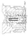
- the apparatus comprises a body 10 in which is formed a plunger bore 11.
- a pumping plunger 12 is slidably mounted in the bore and forms with the inner end of the bore, a pump chamber 13.
- the pumping plunger projects from the bore and is biased outwardly of the bore in known manner, by a plunger return spring (not shown).
- the plunger in use is driven inwardly against the action of the spring by an engine driven cam also not shown.
- the apparatus also includes a fuel injection nozzle having a stepped body 14, the wider portion of which is engaged by a cap nut 15 which is in screw thread engagement with the body 10.
- a distance piece 16 which is located next to the nozzle body and a spring housing 17 which is positioned intermediate the distance piece and the body 10.
- the fuel injection nozzle includes a valve member of the inwardly opening type which is engagable with a seating defined in the nozzle body, to prevent flow of fuel through an outlet orifice or orifices 18A.
- the valve member is biased into engagement with the seating by a coiled compression spring 18 which is interposed between a pair of cup shaped spring abutments 19, 20 which are slidable in the manner of pistons, within a cylindrical recess which extends longitudinally within the spring housing 17.
- the abutment 19 engages with a reduced portion 21 of the nozzle valve member, the reduced portion extending with clearance through an opening formed in the distance piece 16.
- the space about the distance piece is vented to a drain.
- the nozzle valve member is lifted from the seating against the action of the spring 18 by a force developed by fuel under pressure supplied to a nozzle inlet 22, and which acts upon a small area of the nozzle valve member.
- the space 23 defined between the spring abutments 19, 20 is connected by means of a passage 24 in the spring housing and a further passage 25 in the body 10, with a flow connection 26 of a spill valve 27.
- the spill valve includes a valve member 28 which is urged into engagement with a seating by energising an electromagnetic actuator not shown. When the actuator is de-energised, the valve member is lifted from the seating by means of a spring, to place the flow connection 26 in communication with a further flow connection 29 which is in communication with the pump chamber 13 by way of a passage 30.
- a cylindrical stepped blind drilling 32 Formed in the body 10 is a cylindrical stepped blind drilling 32 the wider and open end of which is closed by the end face of the spring housing 17.
- a pilot piston 33 Slidable in the narrower portion of the drilling is a pilot piston 33 which has an end face 34 adjacent the blind end of the drilling, of generally conical form. The inner portion of the end face 34 serves as a closure for an orifice 35 which extends between the blind end of the drilling and the pump chamber 13.
- the pilot piston is urged to a first position in which the orifice 35 is closed by means of a coiled compression spring 36 which is interposed between a flange on the pilot piston and the end face of the spring housing, the spring being located in the wider portion of the drilling 32.
- a further blind drilling 37 having its open end facing towards the spring housing and slidable in this drilling is a piston member 38.
- the piston member is biased outwardly by means of a further spring 39 interposed between the piston member and the blind end of the drilling 37.
- the piston member 38 projects from the drilling 37 and engages a peg 40.
- the peg 40 is slidably mounted in an opening formed in the end face of the spring housing and it engages the spring abutment 20.
- the peg is provided with a flange 41 which lies within the coils of the spring 36 and in the rest position, a clearance 42 is established between the flange and the end face of the spring housing.
- the flange 41 can be engaged as will be described, by the skirt of the pilot piston 33 in the second position thereof, a clearance 43 being established therebetween in the rest position.
- a port 44 which is spaced from the blind end of the drilling.
- the port in the rest position of the apparatus is covered by the pilot piston 33.
- the port 44 communicates with the nozzle inlet 22 by way of communicating passages in the body 10, the spring housing 17 and the distance piece 16.
- a circumferential groove 45 which communicates with ports 46 which extend through the skirt of the pilot piston into the blind end of the drilling 37.
- a slot 44A which in the rest position of the pilot piston is uncovered to the groove 45.
- the wider end of the drilling 32 communicates with a fuel inlet passage 47 and this by way of openings formed in the skirt of the cap nut, communicates in use with a fuel supply passage formed in the cylinder head of the associated engine.
- the peg 40 is fluted and defines longitudinal grooves 48 in its wall.
- the grooves communicate with a further longitudinal groove 49 formed in the outer wall of the spring abutment 20.
- a restricted passage 50 which communicates by way of the openings in the skirt of the cap nut, with the fuel supply.
- the remote end of the groove 49 communicates with the space 23 defined between the two spring abutments and intermediate its ends the skirt of the spring abutment 20 is provided with openings into the groove.
- Figures 1 and 2 show the parts of the apparatus in the rest position and assuming that the engine driven cam starts to move the plunger inwardly, fuel will be displaced from the pump chamber 13 and will flow by way of the spill valve 27 to the space 23 and from the space by way of the grooves 48 and 49 to the fuel supply passage 47. Some fuel can also flow through the restricted passage 50.
- a further effect is that the flange 41 is brought into sealing engagement with the end face of the spring housing thereby closing the grooves 48 in the peg 40. Prior to engagement of the flange with the spring housing the port 44 is uncovered by the pilot piston to allow direct communication of the pumping chamber 13 with the inlet 22 of the fuel injection nozzle.
- the spill valve 27 is opened and this has the effect of lowering the pressure of fuel supplied to the inlet 22 of the fuel injection nozzle and since the fuel flow through the spill valve takes place through the space 23, the pressure therein is increased.
- the increased pressure in the space 23 acting on the spring abutment 19, generates a force acting to assist the spring 18 thereby resulting in rapid closure of the valve member of the fuel injection nozzle.
- the fuel pressure in the space 23 is controlled by the restricted passage 50 since the grooves 48 are closed, and the spring abutment 20 is largely pressure balanced so far as this pressure is concerned.
- the size of the orifice 35 determines the area of the pilot piston which is exposed to the pressure in the pump chamber and in conjunction with the force exerted by the springs 36, 39, determines the pressure at which the pilot piston starts to move.
- the size of the orifice is chosen so that even in engine overrun conditions when the spill valve might never be closed, the pressure of fuel developed in the pumping chamber is not high enough to cause movement of the pilot piston. It is therefore possible to control the start of movement of the pilot piston and hence the timing of the start of fuel delivery over a wide range of engine speeds.
Landscapes
- Engineering & Computer Science (AREA)
- Chemical & Material Sciences (AREA)
- Combustion & Propulsion (AREA)
- Mechanical Engineering (AREA)
- General Engineering & Computer Science (AREA)
- Fuel-Injection Apparatus (AREA)
- Details Of Reciprocating Pumps (AREA)
Applications Claiming Priority (2)
| Application Number | Priority Date | Filing Date | Title |
|---|---|---|---|
| GB9615663 | 1996-07-25 | ||
| GBGB9615663.3A GB9615663D0 (en) | 1996-07-25 | 1996-07-25 | Fuel pumping apparatus |
Publications (2)
| Publication Number | Publication Date |
|---|---|
| EP0821154A1 true EP0821154A1 (fr) | 1998-01-28 |
| EP0821154B1 EP0821154B1 (fr) | 2002-01-02 |
Family
ID=10797512
Family Applications (1)
| Application Number | Title | Priority Date | Filing Date |
|---|---|---|---|
| EP97305209A Expired - Lifetime EP0821154B1 (fr) | 1996-07-25 | 1997-07-14 | Dispositif de pompage de combustible |
Country Status (5)
| Country | Link |
|---|---|
| US (1) | US5878958A (fr) |
| EP (1) | EP0821154B1 (fr) |
| DE (1) | DE69709454T2 (fr) |
| ES (1) | ES2166509T3 (fr) |
| GB (1) | GB9615663D0 (fr) |
Families Citing this family (5)
| Publication number | Priority date | Publication date | Assignee | Title |
|---|---|---|---|---|
| US6161770A (en) | 1994-06-06 | 2000-12-19 | Sturman; Oded E. | Hydraulically driven springless fuel injector |
| US6257499B1 (en) | 1994-06-06 | 2001-07-10 | Oded E. Sturman | High speed fuel injector |
| US6085991A (en) | 1998-05-14 | 2000-07-11 | Sturman; Oded E. | Intensified fuel injector having a lateral drain passage |
| RU2253032C2 (ru) * | 2003-02-25 | 2005-05-27 | Закрытое акционерное общество Башдизельпрецизион | Электрогидроуправляемая форсунка для аккумуляторных систем топливоподачи |
| DE102005012929A1 (de) * | 2005-03-21 | 2006-09-28 | Robert Bosch Gmbh | Kraftstoffinjektor mit direkter Steuerung des Einspritzventilglieds und variabler Übersetzung |
Citations (4)
| Publication number | Priority date | Publication date | Assignee | Title |
|---|---|---|---|---|
| US3403861A (en) * | 1966-03-30 | 1968-10-01 | Bosch Gmbh Robert | Fuel injection valve for preliminary and main injection |
| GB2105406A (en) * | 1981-09-05 | 1983-03-23 | Lucas Ind Plc | Fuel injection nozzle systems for compression ignition engines |
| US4811899A (en) * | 1986-09-01 | 1989-03-14 | Robert Bosch Gmbh | Apparatus for generating pre-injections in unit fuel injectors |
| EP0418800A2 (fr) * | 1989-09-20 | 1991-03-27 | L'orange Gmbh | Dispositif d'injection de combustible pour un moteur à combustion interne |
Family Cites Families (8)
| Publication number | Priority date | Publication date | Assignee | Title |
|---|---|---|---|---|
| GB418800A (en) * | 1934-03-29 | 1934-10-31 | Alfred Janisch | Pneumatic mattress |
| GB541100A (en) * | 1940-05-11 | 1941-11-12 | Cav Ltd | Improvements relating to fuel injection means for internal combustion engines |
| US2408288A (en) * | 1942-11-13 | 1946-09-24 | Bendix Aviat Corp | Fuel injection apparatus |
| US2762654A (en) * | 1952-07-01 | 1956-09-11 | Gen Motors Corp | Fuel injection device |
| US4408718A (en) * | 1981-09-25 | 1983-10-11 | General Motors Corporation | Electromagnetic unit fuel injector |
| DE3224769A1 (de) * | 1981-11-19 | 1983-05-26 | Robert Bosch Gmbh, 7000 Stuttgart | Kraftstoffeinspritzeinrichtung fuer brennkraftmaschinen, insbesondere pumpeduese fuer dieselbrennkraftmaschinen |
| US4527738A (en) * | 1982-06-18 | 1985-07-09 | Caterpillar Tractor Co. | Modular unit fluid pump-injector |
| US5423484A (en) * | 1994-03-17 | 1995-06-13 | Caterpillar Inc. | Injection rate shaping control ported barrel for a fuel injection system |
-
1996
- 1996-07-25 GB GBGB9615663.3A patent/GB9615663D0/en active Pending
-
1997
- 1997-07-14 ES ES97305209T patent/ES2166509T3/es not_active Expired - Lifetime
- 1997-07-14 DE DE69709454T patent/DE69709454T2/de not_active Expired - Lifetime
- 1997-07-14 EP EP97305209A patent/EP0821154B1/fr not_active Expired - Lifetime
- 1997-07-22 US US08/898,447 patent/US5878958A/en not_active Expired - Lifetime
Patent Citations (4)
| Publication number | Priority date | Publication date | Assignee | Title |
|---|---|---|---|---|
| US3403861A (en) * | 1966-03-30 | 1968-10-01 | Bosch Gmbh Robert | Fuel injection valve for preliminary and main injection |
| GB2105406A (en) * | 1981-09-05 | 1983-03-23 | Lucas Ind Plc | Fuel injection nozzle systems for compression ignition engines |
| US4811899A (en) * | 1986-09-01 | 1989-03-14 | Robert Bosch Gmbh | Apparatus for generating pre-injections in unit fuel injectors |
| EP0418800A2 (fr) * | 1989-09-20 | 1991-03-27 | L'orange Gmbh | Dispositif d'injection de combustible pour un moteur à combustion interne |
Also Published As
| Publication number | Publication date |
|---|---|
| GB9615663D0 (en) | 1996-09-04 |
| DE69709454D1 (de) | 2002-02-07 |
| US5878958A (en) | 1999-03-09 |
| DE69709454T2 (de) | 2002-08-14 |
| ES2166509T3 (es) | 2002-04-16 |
| EP0821154B1 (fr) | 2002-01-02 |
Similar Documents
| Publication | Publication Date | Title |
|---|---|---|
| US4572433A (en) | Electromagnetic unit fuel injector | |
| US4129254A (en) | Electromagnetic unit fuel injector | |
| US5150688A (en) | Magnet valve, in particular for fuel injection pumps | |
| EP0269289A2 (fr) | Pompe-injecteur pour moteur diesel à fermeture assistée de l'aiguille d'injecteur par la pression de décharge | |
| US6994273B2 (en) | Fuel injection valve for internal combustion engines | |
| CA1189400A (fr) | Injecteur a commande electrique | |
| EP0889230B1 (fr) | Injecteur de combustible | |
| JPH0118260B2 (fr) | ||
| US4941612A (en) | Unit fuel injector | |
| EP0372714B1 (fr) | Injecteur de combustible | |
| US5901685A (en) | Fuel injector with damping means | |
| EP0372712B1 (fr) | Soupape électromagnétique | |
| US4653448A (en) | Fuel injection device | |
| EP0548329A4 (en) | High pressure unit fuel injector with timing chamber pressure control valve | |
| US4201160A (en) | Fuel injection systems | |
| US5626119A (en) | Fuel system | |
| EP0736687B1 (fr) | Dispositif d'injection de carburant | |
| US5478213A (en) | Fuel injection pump | |
| US5458103A (en) | Fuel injection arrangement for internal combustion engines | |
| US4423715A (en) | Fuel pump-injector unitary assembly for internal combustion engine | |
| US5878958A (en) | Fuel pumping apparatus | |
| US6029902A (en) | Fuel injector with isolated spring chamber | |
| US4537352A (en) | Fuel injection apparatus | |
| US5333588A (en) | Pump/injector | |
| US4793315A (en) | Fuel pumping apparatus |
Legal Events
| Date | Code | Title | Description |
|---|---|---|---|
| PUAI | Public reference made under article 153(3) epc to a published international application that has entered the european phase |
Free format text: ORIGINAL CODE: 0009012 |
|
| AK | Designated contracting states |
Kind code of ref document: A1 Designated state(s): AT BE CH DE DK ES FI FR GB GR IE IT LI LU MC NL PT SE |
|
| 17P | Request for examination filed |
Effective date: 19980715 |
|
| RBV | Designated contracting states (corrected) |
Designated state(s): DE ES FR GB IT |
|
| RAP1 | Party data changed (applicant data changed or rights of an application transferred) |
Owner name: LUCAS INDUSTRIES LIMITED |
|
| 17Q | First examination report despatched |
Effective date: 20000322 |
|
| RAP1 | Party data changed (applicant data changed or rights of an application transferred) |
Owner name: DELPHI TECHNOLOGIES, INC. |
|
| GRAG | Despatch of communication of intention to grant |
Free format text: ORIGINAL CODE: EPIDOS AGRA |
|
| GRAG | Despatch of communication of intention to grant |
Free format text: ORIGINAL CODE: EPIDOS AGRA |
|
| GRAH | Despatch of communication of intention to grant a patent |
Free format text: ORIGINAL CODE: EPIDOS IGRA |
|
| GRAH | Despatch of communication of intention to grant a patent |
Free format text: ORIGINAL CODE: EPIDOS IGRA |
|
| GRAA | (expected) grant |
Free format text: ORIGINAL CODE: 0009210 |
|
| REG | Reference to a national code |
Ref country code: GB Ref legal event code: IF02 |
|
| AK | Designated contracting states |
Kind code of ref document: B1 Designated state(s): DE ES FR GB IT |
|
| REF | Corresponds to: |
Ref document number: 69709454 Country of ref document: DE Date of ref document: 20020207 |
|
| REG | Reference to a national code |
Ref country code: ES Ref legal event code: FG2A Ref document number: 2166509 Country of ref document: ES Kind code of ref document: T3 |
|
| ET | Fr: translation filed | ||
| PLBE | No opposition filed within time limit |
Free format text: ORIGINAL CODE: 0009261 |
|
| STAA | Information on the status of an ep patent application or granted ep patent |
Free format text: STATUS: NO OPPOSITION FILED WITHIN TIME LIMIT |
|
| 26N | No opposition filed | ||
| PGFP | Annual fee paid to national office [announced via postgrant information from national office to epo] |
Ref country code: GB Payment date: 20030711 Year of fee payment: 7 |
|
| PGFP | Annual fee paid to national office [announced via postgrant information from national office to epo] |
Ref country code: ES Payment date: 20030806 Year of fee payment: 7 |
|
| PG25 | Lapsed in a contracting state [announced via postgrant information from national office to epo] |
Ref country code: GB Free format text: LAPSE BECAUSE OF NON-PAYMENT OF DUE FEES Effective date: 20040714 |
|
| PG25 | Lapsed in a contracting state [announced via postgrant information from national office to epo] |
Ref country code: ES Free format text: LAPSE BECAUSE OF NON-PAYMENT OF DUE FEES Effective date: 20040715 |
|
| GBPC | Gb: european patent ceased through non-payment of renewal fee |
Effective date: 20040714 |
|
| PG25 | Lapsed in a contracting state [announced via postgrant information from national office to epo] |
Ref country code: IT Free format text: LAPSE BECAUSE OF NON-PAYMENT OF DUE FEES;WARNING: LAPSES OF ITALIAN PATENTS WITH EFFECTIVE DATE BEFORE 2007 MAY HAVE OCCURRED AT ANY TIME BEFORE 2007. THE CORRECT EFFECTIVE DATE MAY BE DIFFERENT FROM THE ONE RECORDED. Effective date: 20050714 |
|
| REG | Reference to a national code |
Ref country code: ES Ref legal event code: FD2A Effective date: 20040715 |
|
| PGFP | Annual fee paid to national office [announced via postgrant information from national office to epo] |
Ref country code: FR Payment date: 20080718 Year of fee payment: 12 |
|
| REG | Reference to a national code |
Ref country code: FR Ref legal event code: ST Effective date: 20100331 |
|
| PG25 | Lapsed in a contracting state [announced via postgrant information from national office to epo] |
Ref country code: FR Free format text: LAPSE BECAUSE OF NON-PAYMENT OF DUE FEES Effective date: 20090731 |
|
| PGFP | Annual fee paid to national office [announced via postgrant information from national office to epo] |
Ref country code: DE Payment date: 20100707 Year of fee payment: 14 |
|
| PG25 | Lapsed in a contracting state [announced via postgrant information from national office to epo] |
Ref country code: DE Free format text: LAPSE BECAUSE OF NON-PAYMENT OF DUE FEES Effective date: 20120201 |
|
| REG | Reference to a national code |
Ref country code: DE Ref legal event code: R119 Ref document number: 69709454 Country of ref document: DE Effective date: 20120201 |