EP0821178A2 - Embrayage commandé automatiquement - Google Patents
Embrayage commandé automatiquement Download PDFInfo
- Publication number
- EP0821178A2 EP0821178A2 EP97109086A EP97109086A EP0821178A2 EP 0821178 A2 EP0821178 A2 EP 0821178A2 EP 97109086 A EP97109086 A EP 97109086A EP 97109086 A EP97109086 A EP 97109086A EP 0821178 A2 EP0821178 A2 EP 0821178A2
- Authority
- EP
- European Patent Office
- Prior art keywords
- clutch
- actuating
- gripping point
- torque
- value
- Prior art date
- Legal status (The legal status is an assumption and is not a legal conclusion. Google has not performed a legal analysis and makes no representation as to the accuracy of the status listed.)
- Ceased
Links
- 230000005540 biological transmission Effects 0.000 claims description 5
- 230000008878 coupling Effects 0.000 claims 4
- 238000010168 coupling process Methods 0.000 claims 4
- 238000005859 coupling reaction Methods 0.000 claims 4
- 238000006073 displacement reaction Methods 0.000 abstract 1
- 230000006978 adaptation Effects 0.000 description 8
- 238000010586 diagram Methods 0.000 description 2
- 238000001514 detection method Methods 0.000 description 1
- 230000000694 effects Effects 0.000 description 1
- 238000005259 measurement Methods 0.000 description 1
- 230000001105 regulatory effect Effects 0.000 description 1
Images
Classifications
-
- F—MECHANICAL ENGINEERING; LIGHTING; HEATING; WEAPONS; BLASTING
- F16—ENGINEERING ELEMENTS AND UNITS; GENERAL MEASURES FOR PRODUCING AND MAINTAINING EFFECTIVE FUNCTIONING OF MACHINES OR INSTALLATIONS; THERMAL INSULATION IN GENERAL
- F16D—COUPLINGS FOR TRANSMITTING ROTATION; CLUTCHES; BRAKES
- F16D48/00—External control of clutches
- F16D48/06—Control by electric or electronic means, e.g. of fluid pressure
- F16D48/066—Control of fluid pressure, e.g. using an accumulator
-
- B—PERFORMING OPERATIONS; TRANSPORTING
- B60—VEHICLES IN GENERAL
- B60W—CONJOINT CONTROL OF VEHICLE SUB-UNITS OF DIFFERENT TYPE OR DIFFERENT FUNCTION; CONTROL SYSTEMS SPECIALLY ADAPTED FOR HYBRID VEHICLES; ROAD VEHICLE DRIVE CONTROL SYSTEMS FOR PURPOSES NOT RELATED TO THE CONTROL OF A PARTICULAR SUB-UNIT
- B60W2540/00—Input parameters relating to occupants
- B60W2540/12—Brake pedal position
-
- F—MECHANICAL ENGINEERING; LIGHTING; HEATING; WEAPONS; BLASTING
- F16—ENGINEERING ELEMENTS AND UNITS; GENERAL MEASURES FOR PRODUCING AND MAINTAINING EFFECTIVE FUNCTIONING OF MACHINES OR INSTALLATIONS; THERMAL INSULATION IN GENERAL
- F16D—COUPLINGS FOR TRANSMITTING ROTATION; CLUTCHES; BRAKES
- F16D2500/00—External control of clutches by electric or electronic means
- F16D2500/10—System to be controlled
- F16D2500/104—Clutch
- F16D2500/10406—Clutch position
- F16D2500/10412—Transmission line of a vehicle
-
- F—MECHANICAL ENGINEERING; LIGHTING; HEATING; WEAPONS; BLASTING
- F16—ENGINEERING ELEMENTS AND UNITS; GENERAL MEASURES FOR PRODUCING AND MAINTAINING EFFECTIVE FUNCTIONING OF MACHINES OR INSTALLATIONS; THERMAL INSULATION IN GENERAL
- F16D—COUPLINGS FOR TRANSMITTING ROTATION; CLUTCHES; BRAKES
- F16D2500/00—External control of clutches by electric or electronic means
- F16D2500/30—Signal inputs
- F16D2500/306—Signal inputs from the engine
- F16D2500/3065—Torque of the engine
-
- F—MECHANICAL ENGINEERING; LIGHTING; HEATING; WEAPONS; BLASTING
- F16—ENGINEERING ELEMENTS AND UNITS; GENERAL MEASURES FOR PRODUCING AND MAINTAINING EFFECTIVE FUNCTIONING OF MACHINES OR INSTALLATIONS; THERMAL INSULATION IN GENERAL
- F16D—COUPLINGS FOR TRANSMITTING ROTATION; CLUTCHES; BRAKES
- F16D2500/00—External control of clutches by electric or electronic means
- F16D2500/30—Signal inputs
- F16D2500/308—Signal inputs from the transmission
- F16D2500/30806—Engaged transmission ratio
- F16D2500/30808—Detection of transmission in neutral
-
- F—MECHANICAL ENGINEERING; LIGHTING; HEATING; WEAPONS; BLASTING
- F16—ENGINEERING ELEMENTS AND UNITS; GENERAL MEASURES FOR PRODUCING AND MAINTAINING EFFECTIVE FUNCTIONING OF MACHINES OR INSTALLATIONS; THERMAL INSULATION IN GENERAL
- F16D—COUPLINGS FOR TRANSMITTING ROTATION; CLUTCHES; BRAKES
- F16D2500/00—External control of clutches by electric or electronic means
- F16D2500/30—Signal inputs
- F16D2500/31—Signal inputs from the vehicle
- F16D2500/3108—Vehicle speed
- F16D2500/3111—Standing still, i.e. signal detecting when the vehicle is standing still or bellow a certain limit speed
-
- F—MECHANICAL ENGINEERING; LIGHTING; HEATING; WEAPONS; BLASTING
- F16—ENGINEERING ELEMENTS AND UNITS; GENERAL MEASURES FOR PRODUCING AND MAINTAINING EFFECTIVE FUNCTIONING OF MACHINES OR INSTALLATIONS; THERMAL INSULATION IN GENERAL
- F16D—COUPLINGS FOR TRANSMITTING ROTATION; CLUTCHES; BRAKES
- F16D2500/00—External control of clutches by electric or electronic means
- F16D2500/30—Signal inputs
- F16D2500/31—Signal inputs from the vehicle
- F16D2500/3114—Vehicle wheels
- F16D2500/3115—Vehicle wheel speed
-
- F—MECHANICAL ENGINEERING; LIGHTING; HEATING; WEAPONS; BLASTING
- F16—ENGINEERING ELEMENTS AND UNITS; GENERAL MEASURES FOR PRODUCING AND MAINTAINING EFFECTIVE FUNCTIONING OF MACHINES OR INSTALLATIONS; THERMAL INSULATION IN GENERAL
- F16D—COUPLINGS FOR TRANSMITTING ROTATION; CLUTCHES; BRAKES
- F16D2500/00—External control of clutches by electric or electronic means
- F16D2500/30—Signal inputs
- F16D2500/314—Signal inputs from the user
- F16D2500/31406—Signal inputs from the user input from pedals
- F16D2500/31426—Brake pedal position
-
- F—MECHANICAL ENGINEERING; LIGHTING; HEATING; WEAPONS; BLASTING
- F16—ENGINEERING ELEMENTS AND UNITS; GENERAL MEASURES FOR PRODUCING AND MAINTAINING EFFECTIVE FUNCTIONING OF MACHINES OR INSTALLATIONS; THERMAL INSULATION IN GENERAL
- F16D—COUPLINGS FOR TRANSMITTING ROTATION; CLUTCHES; BRAKES
- F16D2500/00—External control of clutches by electric or electronic means
- F16D2500/30—Signal inputs
- F16D2500/314—Signal inputs from the user
- F16D2500/3146—Signal inputs from the user input from levers
- F16D2500/31466—Gear lever
-
- F—MECHANICAL ENGINEERING; LIGHTING; HEATING; WEAPONS; BLASTING
- F16—ENGINEERING ELEMENTS AND UNITS; GENERAL MEASURES FOR PRODUCING AND MAINTAINING EFFECTIVE FUNCTIONING OF MACHINES OR INSTALLATIONS; THERMAL INSULATION IN GENERAL
- F16D—COUPLINGS FOR TRANSMITTING ROTATION; CLUTCHES; BRAKES
- F16D2500/00—External control of clutches by electric or electronic means
- F16D2500/70—Details about the implementation of the control system
- F16D2500/704—Output parameters from the control unit; Target parameters to be controlled
- F16D2500/70422—Clutch parameters
- F16D2500/70438—From the output shaft
- F16D2500/7044—Output shaft torque
Definitions
- the invention relates to an automatically controlled clutch, which is between the engine and drive wheels in the drive train Motor vehicle with arbitrary or manual between Idle and gears shiftable transmission is arranged, with a control device actuating an actuating unit of the clutch, which depending on given by a assigned sensor technology works parameters.
- the operating behavior of the automatic clutch is constant Subject to changes, such as changing Temperatures as well as signs of wear and tear are caused.
- the object of the invention is now a constant operating behavior of the automatic To ensure clutch.
- the invention is based on the general idea of letting the control device work with a constantly adapted gripping point actuating stroke, so that the control device is sufficiently precise knows "when the clutch begins to engage when engaging, or has almost opened when disengaging.
- the adaptation according to the invention takes into account, on the one hand, that larger changes in the grip point actuating stroke can occur relatively frequently, in particular due to temperature influences. Since only a fraction, for example half, of the deviation between the previously stored gripping point actuating stroke and an actually executed gripping point actuating stroke is taken into account when adapting, changes in the position of the gripping point can be changed Direction of change as well as rapid changes in the gripping point position with the same direction of direction can be achieved. As a result, the gripping point adjustment stroke stored in each case lies within a narrow tolerance band close to the optimum.
- the control device stores continuously adapted data which reflect the dependence of the torque transmitted by the clutch on the actuating stroke of the actuating unit, ie as a result the control device knows the characteristic curve between the actuating stroke and clutch torque.
- This characteristic curve is essentially determined by its gradient (slope) and the position of the gripping point.
- the gradient can change when changing a gear and the automatic engagement and disengagement be determined because the torque transmitted by the clutch through the torque generated by the engine and the time Change in the speed of the engine is determined. If so when changing the stroke, the torque of the motor as well as the change in engine speed over time can be a value for each of the above Determine gradients.
- control device in clutch control constantly updated characteristic curve between Take the stroke and clutch torque into account.
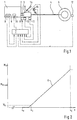
- a motor-driven actuating unit 6 is used to actuate the clutch 2 and is actuated by means of a control device 7 as a function of various parameters, for the detection of which the control device 7 is connected on the input side to a corresponding sensor system.
- This sensor system comprises sensors 9 on the motor side, from the signals of which the speed of the motor and the respectively effective torque M M can be taken.
- a sensor 10 is assigned to the actuating unit 6 and detects the actuating stroke s of the actuating unit 6.
- a transmission-side sensor 11 registers whether the transmission 3 is switched to idle or which gear is selected.
- Wheel-side sensors 12 detect the rotational speed of the vehicle wheels.
- a sensor arrangement 13 which, for example, with the shift lever 14 of the Gear 3 can cooperate, can recognize whether the Driver wants to shift the transmission 3.
- the actuator (pedal) of the service brake (not shown) assigned a sensor 15 to the vehicle, whose signals indicate a brake application.
- the control device 7 is designed such that it increases the torque that can be transmitted by the clutch 2 in accordance with a predetermined increase or decrease tax able In this context, it is important that the control device 7 knows "what value the torque M K that can be transmitted by the clutch has for the respectively set actuating stroke s of the actuating unit 6.
- Fig. 2 shows an example of the dependence of the transferable clutch torque M K on the actuating stroke s.
- a curve K a maximum transferable torque is reached in an end position s E , which is clearly above the maximum torque M Mmax of the vehicle engine 1.
- the clutch 2 is fully opened so that no torque can be transmitted.
- the gripping point of the clutch 2 is reached with an actuating stroke s G , ie the clutch 2 is able to transmit a very low torque M G of, for example, 6 Nm.
- M G of, for example, 6 Nm.
- control device 7 constantly characteristic values or data for the curve K. determined and stored, so that the control device 7 according to a continuously adapted characteristic curve K is able to work.
- M K M M - Jd ⁇ / German
- M M denotes the torque generated by the motor
- J the moment of inertia of the motor
- ⁇ the speed of the motor
- control device 7 Gripping point position can determine.
- the actuating unit 6 can be set such that the torque M K transmitted by the clutch and the torque M M generated by the engine have the value M G.
- the sensor 10 then supplies the signal for the actuating path s G assigned to the gripping point of the clutch, ie the gripping point position of the actuating unit 6.
- the transmissible torque M K which is currently set on the clutch 2 can be obtained from the signals from the sensors which represent the respective torque of the engine 1 and its speed change 9 can be determined.
- the respective adjustment paths of the actuator 6 are detected by evaluating the signals from the sensor 10. As a result, the ratio between the change in travel and the change in the torque transmitted by clutch 2, ie the gradient of curve K, can be determined.
- predetermined values for the actuating stroke s G assigned to the gripping point and the gradient of the curve K are initially stored. If a value deviating therefrom is now determined in the next subsequent gripping point determination, the control device 7 corrects the stored value by a predetermined fraction of the deviation, preferably by half the deviation. This adaptation is repeated the next time the gripping point is determined, ie if the last gripping point is found to deviate again from the last stored value of s G , the last stored value is again corrected by half the deviation and so on.
- the value of the actuating stroke s G assigned to the gripping point can be changed by at most 0.2 mm during an adaptation step.
- the control device 7 constantly knows a curve K that approximates the actual characteristic curve for the dependence of the torque M K that can be transmitted by the clutch 2 on the travel s.
- the control device 7 knows with a high degree of accuracy at which actuating stroke s G the gripping point is reached. There is therefore the possibility that the control device 7 can set predetermined clutch torques with high accuracy, although the operating behavior of the clutch 2 and of the associated control unit 6 change constantly can.
Landscapes
- Physics & Mathematics (AREA)
- Fluid Mechanics (AREA)
- Engineering & Computer Science (AREA)
- General Engineering & Computer Science (AREA)
- Mechanical Engineering (AREA)
- Hydraulic Clutches, Magnetic Clutches, Fluid Clutches, And Fluid Joints (AREA)
- Arrangement And Mounting Of Devices That Control Transmission Of Motive Force (AREA)
Applications Claiming Priority (2)
| Application Number | Priority Date | Filing Date | Title |
|---|---|---|---|
| DE19630014A DE19630014C2 (de) | 1996-07-25 | 1996-07-25 | Automatisch gesteuerte Kupplung |
| DE19630014 | 1996-07-25 |
Publications (2)
| Publication Number | Publication Date |
|---|---|
| EP0821178A2 true EP0821178A2 (fr) | 1998-01-28 |
| EP0821178A3 EP0821178A3 (fr) | 1999-03-24 |
Family
ID=7800799
Family Applications (1)
| Application Number | Title | Priority Date | Filing Date |
|---|---|---|---|
| EP97109086A Ceased EP0821178A3 (fr) | 1996-07-25 | 1997-06-05 | Embrayage commandé automatiquement |
Country Status (3)
| Country | Link |
|---|---|
| US (1) | US5993352A (fr) |
| EP (1) | EP0821178A3 (fr) |
| DE (1) | DE19630014C2 (fr) |
Cited By (6)
| Publication number | Priority date | Publication date | Assignee | Title |
|---|---|---|---|---|
| EP1000795A3 (fr) * | 1998-11-12 | 2002-01-09 | Eaton Corporation | Détermination du point de contact pour embrayage principal de véhicule |
| EP1201955A1 (fr) * | 2000-10-27 | 2002-05-02 | MAGNETI MARELLI POWERTRAIN S.p.A. | Procédé pour actualiser la fonction de transfert d'un embrayage pendant un changement de vitesse |
| FR2828719A1 (fr) * | 2001-08-16 | 2003-02-21 | Luk Lamellen & Kupplungsbau | Procede servant a commander un embrayage et dispositif servant a actionner un embrayage |
| CN103185083A (zh) * | 2012-01-03 | 2013-07-03 | 舍弗勒技术股份两合公司 | 用于求得摩擦离合器的接触点的方法 |
| CN103210230A (zh) * | 2010-11-18 | 2013-07-17 | 舍弗勒技术股份两合公司 | 双离合器系统的串扰行为的得出 |
| CN104053923A (zh) * | 2012-02-20 | 2014-09-17 | 舍弗勒技术有限两合公司 | 用于确定离合器转矩要求的方法 |
Families Citing this family (17)
| Publication number | Priority date | Publication date | Assignee | Title |
|---|---|---|---|---|
| DE19812629B4 (de) * | 1998-03-23 | 2010-08-26 | Bayerische Motoren Werke Aktiengesellschaft | Steuerung für eine automatisch betätigte Kupplung |
| DE19951946A1 (de) * | 1998-11-03 | 2000-05-04 | Luk Getriebe Systeme Gmbh | Kraftfahrzeug |
| DE19919328A1 (de) * | 1999-04-28 | 2000-11-02 | Mannesmann Sachs Ag | Verfahren zum Erhalten von einen Betriebszustand einer Reibungskupplung charakterisierenden Information |
| AU6147800A (en) * | 1999-06-08 | 2000-12-28 | Luk Lamellen Und Kupplungsbau Beteiligungs Kg | Method for operating an actuation device of an automated transmission |
| BR0112392A (pt) * | 2000-06-23 | 2004-01-06 | Luk Lamellen & Kupplungsbau | Processo e dispositivo para compensação da influência dos números de rotações sobre a curva caracterìstica de uma embreagem |
| WO2002059493A1 (fr) * | 2001-01-24 | 2002-08-01 | Luk Lamellen Und Kupplungsbau Beteiligungs Kg | Procede pour adapter la courbe caracteristique d'un embrayage automatique de vehicule |
| DE10306934A1 (de) * | 2003-02-19 | 2004-09-02 | Zf Friedrichshafen Ag | Verfahren zur Anlegepunktbestimmung der Kupplung eines automatisierten Schaltgetriebes |
| EP1614922A3 (fr) * | 2004-07-06 | 2009-12-23 | LuK Lamellen und Kupplungsbau Beteiligungs KG | Méthode et dispositif pour référencer un capteur incrémentiel de position dans un dispositif d'actuation controllé électroniquement d'un embrayage |
| ATE418687T1 (de) * | 2006-02-16 | 2009-01-15 | Luk Lamellen & Kupplungsbau | Verfahren und vorrichtung zum nachstellen einer in einem fahrzeugantriebsstrang befindlichen, von einem aktor betätigten reibungskupplung |
| DE102008028180A1 (de) * | 2007-06-25 | 2009-01-08 | Luk Lamellen Und Kupplungsbau Beteiligungs Kg | Verfahren zur Adaption einer Kupplungskennlinie bei vorhandener Kupplungshysterese |
| DE102008000341A1 (de) * | 2008-02-19 | 2009-08-20 | Zf Friedrichshafen Ag | Verfahren zur Steuerung eines Planeten-Automatgetriebes |
| DE102010024941A1 (de) * | 2009-07-16 | 2011-01-20 | Luk Lamellen Und Kupplungsbau Beteiligungs Kg | Kupplungstastpunkte |
| CN102859224B (zh) * | 2010-04-26 | 2015-06-17 | 舍弗勒技术股份两合公司 | 用于适配汽车动力传动系中离合器的接触点的方法 |
| DE102010039172B4 (de) * | 2010-08-11 | 2023-12-07 | Zf Friedrichshafen Ag | Verfahren zur Ermittlung eines Anlegebetätigungsdruckwertes eines reibschlüssigen Schaltelements |
| SE535667C2 (sv) | 2011-03-14 | 2012-10-30 | Scania Cv Ab | Förfarande och system för bestämning av ett behov av kontaktpunktsadaption |
| DE102012209869A1 (de) | 2011-07-05 | 2013-01-10 | Schaeffler Technologies AG & Co. KG | Verfahren zum Überwachen einer Kupplung |
| JP6119159B2 (ja) * | 2012-09-21 | 2017-04-26 | アイシン精機株式会社 | クラッチ制御装置 |
Family Cites Families (10)
| Publication number | Priority date | Publication date | Assignee | Title |
|---|---|---|---|---|
| GB410346A (en) * | 1933-07-12 | 1934-05-17 | George Benjamin Stern | An automatic electric time switch |
| FR2645805B1 (fr) * | 1989-04-17 | 1995-07-13 | Luk Lamellen & Kupplungsbau | Procede de commande d'un embrayage a friction automatise agissant entre un moteur d'entrainement et une transmission, appareillage pour la mise en oeuvre du procede, et regulation associee d'un embrayage a friction |
| DE4011850B4 (de) * | 1989-04-17 | 2006-04-27 | Luk Lamellen Und Kupplungsbau Beteiligungs Kg | Verfahren zum Steuern einer zwischen einer Antriebsmaschine und einem Getriebe wirksamen automatisierten Reibungskupplung |
| JPH0356719A (ja) * | 1989-07-24 | 1991-03-12 | Zexel Corp | クラッチ制御装置 |
| DE4100372A1 (de) * | 1991-01-09 | 1992-07-16 | Fichtel & Sachs Ag | Anordnung zur regelung des schlupfs einer automatisierten reibungskupplung |
| US5393274A (en) * | 1993-07-19 | 1995-02-28 | Eaton Corporation | Touch point identification algorithm for automatic clutch controller |
| GB2280721B (en) * | 1993-08-03 | 1998-03-11 | Luk Getriebe Systeme Gmbh | Motor vehicle automatic clutch control |
| DE4426260A1 (de) * | 1993-08-03 | 1995-02-09 | Luk Getriebe Systeme Gmbh | Kraftfahrzeug |
| DE4434111A1 (de) * | 1994-09-23 | 1996-03-28 | Kongsberg Automotive Technolog | Steuerung für eine automatisch betätigte Kupplung |
| GB9421350D0 (en) * | 1994-10-24 | 1994-12-07 | Eaton Corp | Automated clutch control and calibration |
-
1996
- 1996-07-25 DE DE19630014A patent/DE19630014C2/de not_active Expired - Fee Related
-
1997
- 1997-06-05 EP EP97109086A patent/EP0821178A3/fr not_active Ceased
- 1997-07-11 US US08/893,522 patent/US5993352A/en not_active Expired - Fee Related
Non-Patent Citations (1)
| Title |
|---|
| None |
Cited By (11)
| Publication number | Priority date | Publication date | Assignee | Title |
|---|---|---|---|---|
| EP1000795A3 (fr) * | 1998-11-12 | 2002-01-09 | Eaton Corporation | Détermination du point de contact pour embrayage principal de véhicule |
| EP1201955A1 (fr) * | 2000-10-27 | 2002-05-02 | MAGNETI MARELLI POWERTRAIN S.p.A. | Procédé pour actualiser la fonction de transfert d'un embrayage pendant un changement de vitesse |
| US6658340B2 (en) | 2000-10-27 | 2003-12-02 | Magneti Marelli Powertrain, S.P.A. | Method of updating the transmissibility function of a clutch during a gear change |
| FR2828719A1 (fr) * | 2001-08-16 | 2003-02-21 | Luk Lamellen & Kupplungsbau | Procede servant a commander un embrayage et dispositif servant a actionner un embrayage |
| WO2003016743A1 (fr) * | 2001-08-16 | 2003-02-27 | Luk Lamellen Und Kupplungsbau Beteiligungs Kg | Procede pour commander un embrayage et dispositif pour actionner un embrayage |
| CN103210230A (zh) * | 2010-11-18 | 2013-07-17 | 舍弗勒技术股份两合公司 | 双离合器系统的串扰行为的得出 |
| CN103210230B (zh) * | 2010-11-18 | 2016-01-27 | 舍弗勒技术股份两合公司 | 双离合器系统的串扰行为的得出 |
| CN103185083A (zh) * | 2012-01-03 | 2013-07-03 | 舍弗勒技术股份两合公司 | 用于求得摩擦离合器的接触点的方法 |
| CN103185083B (zh) * | 2012-01-03 | 2017-08-01 | 舍弗勒技术股份两合公司 | 用于求得摩擦离合器的接触点的方法 |
| CN104053923A (zh) * | 2012-02-20 | 2014-09-17 | 舍弗勒技术有限两合公司 | 用于确定离合器转矩要求的方法 |
| CN104053923B (zh) * | 2012-02-20 | 2016-08-24 | 舍弗勒技术股份两合公司 | 用于确定离合器转矩要求的方法 |
Also Published As
| Publication number | Publication date |
|---|---|
| EP0821178A3 (fr) | 1999-03-24 |
| DE19630014C2 (de) | 1998-05-20 |
| DE19630014A1 (de) | 1998-01-29 |
| US5993352A (en) | 1999-11-30 |
Similar Documents
| Publication | Publication Date | Title |
|---|---|---|
| EP0821178A2 (fr) | Embrayage commandé automatiquement | |
| DE19823089B4 (de) | Verfahren und Vorrichtung zum Nullabgleich einer Wegmessung bei einer Kupplung | |
| DE10080639B4 (de) | Kupplungssteuervorrichtung zur automatischen Betätigung einer Kupplung während des Anfahrens | |
| DE19818809A1 (de) | Vorrichtung zur Ansteuerung eines Drehmomentübertragungssystems | |
| DE19721034A1 (de) | Kraftfahrzeug | |
| DE19702449A1 (de) | Vorrichtung zur Betätigung | |
| EP1442239A1 (fr) | Procede de commande de circuit d'une boite de vitesses couplable sous charge | |
| DE10032906A1 (de) | Steuerungsvorrichtung | |
| EP0759513B1 (fr) | Régulation d'un embrayage automatique en fonction du couple moteur | |
| DE102007006803B4 (de) | Verfahren und Vorrichtung zum Vermindern von Rupfschwingungen in einem Kraftfahrzeugantriebsstrang | |
| EP0928376B1 (fr) | Embrayage a commande automatique | |
| EP1614922A2 (fr) | Méthode et dispositif pour référencer un capteur incrémentiel de position dans un dispositif d'actuation controllé électroniquement d'un embrayage | |
| DE19750824C2 (de) | Verfahren zur Erfassung einer Grenzstellungsposition einer Kraftfahrzeugkupplung | |
| DE19903554C2 (de) | Kraftfahrzeug-Antriebsstrang und Verfahren zu seiner Steuerung | |
| DE10247970A1 (de) | Verfahren zum Anfahren eines Kraftfahrzeuges | |
| WO2008104148A1 (fr) | Procédé et dispositif de commande des embrayages d'une boîte de vitesses à couplage parallèle lors d'un changement de vitesse | |
| EP1632694B1 (fr) | Chaîne cinématique comportant une boîte de vitesses comportant deux arbres d'entrée en parallèle | |
| DE102005026472B4 (de) | Verfahren und Vorrichtung zum Steuern des Schließens einer automatisierten Kupplung im Antriebsstrang eines Kraftfahrzeugs | |
| DE102008000341A1 (de) | Verfahren zur Steuerung eines Planeten-Automatgetriebes | |
| DE10261723A1 (de) | Verfahren zur Adaptation einer Schaltkennlinie einer Lastschaltkupplung eines Kraftfahrzeuggetriebes | |
| WO2007144297A1 (fr) | Procédé de commande d'un mode de manœuvre d'un véhicule automobile | |
| DE102016004796A1 (de) | Verfahren und System zur Steuerung einer Kupplung eines Fahrzeugs | |
| DE10034744B4 (de) | Verfahren zur Bestimmung des von einer Reibungskupplung eines mit einem Antriebsmotor gekoppelten Lastschaltgetriebes übertragenen Moments | |
| DE102011006386A1 (de) | Verfahren zur Freigabe einer Rückschaltung in einem automatischen Fahrzeuggetriebe | |
| DE19639292C1 (de) | Automatisch gesteuerte Kupplung |
Legal Events
| Date | Code | Title | Description |
|---|---|---|---|
| PUAI | Public reference made under article 153(3) epc to a published international application that has entered the european phase |
Free format text: ORIGINAL CODE: 0009012 |
|
| AK | Designated contracting states |
Kind code of ref document: A2 Designated state(s): DE FR GB IT |
|
| AX | Request for extension of the european patent |
Free format text: AL;LT;LV;RO;SI |
|
| PUAL | Search report despatched |
Free format text: ORIGINAL CODE: 0009013 |
|
| AK | Designated contracting states |
Kind code of ref document: A3 Designated state(s): AT BE CH DE DK ES FI FR GB GR IE IT LI LU MC NL PT SE |
|
| AX | Request for extension of the european patent |
Free format text: AL;LT;LV;RO;SI |
|
| RAP1 | Party data changed (applicant data changed or rights of an application transferred) |
Owner name: DAIMLERCHRYSLER AG |
|
| 17P | Request for examination filed |
Effective date: 19990226 |
|
| AKX | Designation fees paid |
Free format text: DE FR GB IT |
|
| 17Q | First examination report despatched |
Effective date: 20010116 |
|
| GRAG | Despatch of communication of intention to grant |
Free format text: ORIGINAL CODE: EPIDOS AGRA |
|
| STAA | Information on the status of an ep patent application or granted ep patent |
Free format text: STATUS: THE APPLICATION HAS BEEN REFUSED |
|
| 18R | Application refused |
Effective date: 20020418 |