EP0821187B1 - Öldruckerzeuger und Antriebsanordnung - Google Patents
Öldruckerzeuger und Antriebsanordnung Download PDFInfo
- Publication number
- EP0821187B1 EP0821187B1 EP97112856A EP97112856A EP0821187B1 EP 0821187 B1 EP0821187 B1 EP 0821187B1 EP 97112856 A EP97112856 A EP 97112856A EP 97112856 A EP97112856 A EP 97112856A EP 0821187 B1 EP0821187 B1 EP 0821187B1
- Authority
- EP
- European Patent Office
- Prior art keywords
- shaft
- oil pressure
- pressure generator
- engine
- rotating
- Prior art date
- Legal status (The legal status is an assumption and is not a legal conclusion. Google has not performed a legal analysis and makes no representation as to the accuracy of the status listed.)
- Expired - Lifetime
Links
Images



Classifications
-
- B—PERFORMING OPERATIONS; TRANSPORTING
- B60—VEHICLES IN GENERAL
- B60K—ARRANGEMENT OR MOUNTING OF PROPULSION UNITS OR OF TRANSMISSIONS IN VEHICLES; ARRANGEMENT OR MOUNTING OF PLURAL DIVERSE PRIME-MOVERS IN VEHICLES; AUXILIARY DRIVES FOR VEHICLES; INSTRUMENTATION OR DASHBOARDS FOR VEHICLES; ARRANGEMENTS IN CONNECTION WITH COOLING, AIR INTAKE, GAS EXHAUST OR FUEL SUPPLY OF PROPULSION UNITS IN VEHICLES
- B60K6/00—Arrangement or mounting of plural diverse prime-movers for mutual or common propulsion, e.g. hybrid propulsion systems comprising electric motors and internal combustion engines
- B60K6/20—Arrangement or mounting of plural diverse prime-movers for mutual or common propulsion, e.g. hybrid propulsion systems comprising electric motors and internal combustion engines the prime-movers consisting of electric motors and internal combustion engines, e.g. HEVs
- B60K6/22—Arrangement or mounting of plural diverse prime-movers for mutual or common propulsion, e.g. hybrid propulsion systems comprising electric motors and internal combustion engines the prime-movers consisting of electric motors and internal combustion engines, e.g. HEVs characterised by apparatus, components or means specially adapted for HEVs
- B60K6/26—Arrangement or mounting of plural diverse prime-movers for mutual or common propulsion, e.g. hybrid propulsion systems comprising electric motors and internal combustion engines the prime-movers consisting of electric motors and internal combustion engines, e.g. HEVs characterised by apparatus, components or means specially adapted for HEVs characterised by the motors or the generators
-
- B—PERFORMING OPERATIONS; TRANSPORTING
- B60—VEHICLES IN GENERAL
- B60K—ARRANGEMENT OR MOUNTING OF PROPULSION UNITS OR OF TRANSMISSIONS IN VEHICLES; ARRANGEMENT OR MOUNTING OF PLURAL DIVERSE PRIME-MOVERS IN VEHICLES; AUXILIARY DRIVES FOR VEHICLES; INSTRUMENTATION OR DASHBOARDS FOR VEHICLES; ARRANGEMENTS IN CONNECTION WITH COOLING, AIR INTAKE, GAS EXHAUST OR FUEL SUPPLY OF PROPULSION UNITS IN VEHICLES
- B60K6/00—Arrangement or mounting of plural diverse prime-movers for mutual or common propulsion, e.g. hybrid propulsion systems comprising electric motors and internal combustion engines
- B60K6/20—Arrangement or mounting of plural diverse prime-movers for mutual or common propulsion, e.g. hybrid propulsion systems comprising electric motors and internal combustion engines the prime-movers consisting of electric motors and internal combustion engines, e.g. HEVs
- B60K6/22—Arrangement or mounting of plural diverse prime-movers for mutual or common propulsion, e.g. hybrid propulsion systems comprising electric motors and internal combustion engines the prime-movers consisting of electric motors and internal combustion engines, e.g. HEVs characterised by apparatus, components or means specially adapted for HEVs
- B60K6/36—Arrangement or mounting of plural diverse prime-movers for mutual or common propulsion, e.g. hybrid propulsion systems comprising electric motors and internal combustion engines the prime-movers consisting of electric motors and internal combustion engines, e.g. HEVs characterised by apparatus, components or means specially adapted for HEVs characterised by the transmission gearings
- B60K6/365—Arrangement or mounting of plural diverse prime-movers for mutual or common propulsion, e.g. hybrid propulsion systems comprising electric motors and internal combustion engines the prime-movers consisting of electric motors and internal combustion engines, e.g. HEVs characterised by apparatus, components or means specially adapted for HEVs characterised by the transmission gearings with the gears having orbital motion
-
- B—PERFORMING OPERATIONS; TRANSPORTING
- B60—VEHICLES IN GENERAL
- B60K—ARRANGEMENT OR MOUNTING OF PROPULSION UNITS OR OF TRANSMISSIONS IN VEHICLES; ARRANGEMENT OR MOUNTING OF PLURAL DIVERSE PRIME-MOVERS IN VEHICLES; AUXILIARY DRIVES FOR VEHICLES; INSTRUMENTATION OR DASHBOARDS FOR VEHICLES; ARRANGEMENTS IN CONNECTION WITH COOLING, AIR INTAKE, GAS EXHAUST OR FUEL SUPPLY OF PROPULSION UNITS IN VEHICLES
- B60K6/00—Arrangement or mounting of plural diverse prime-movers for mutual or common propulsion, e.g. hybrid propulsion systems comprising electric motors and internal combustion engines
- B60K6/20—Arrangement or mounting of plural diverse prime-movers for mutual or common propulsion, e.g. hybrid propulsion systems comprising electric motors and internal combustion engines the prime-movers consisting of electric motors and internal combustion engines, e.g. HEVs
- B60K6/22—Arrangement or mounting of plural diverse prime-movers for mutual or common propulsion, e.g. hybrid propulsion systems comprising electric motors and internal combustion engines the prime-movers consisting of electric motors and internal combustion engines, e.g. HEVs characterised by apparatus, components or means specially adapted for HEVs
- B60K6/38—Arrangement or mounting of plural diverse prime-movers for mutual or common propulsion, e.g. hybrid propulsion systems comprising electric motors and internal combustion engines the prime-movers consisting of electric motors and internal combustion engines, e.g. HEVs characterised by apparatus, components or means specially adapted for HEVs characterised by the driveline clutches
- B60K6/383—One-way clutches or freewheel devices
-
- B—PERFORMING OPERATIONS; TRANSPORTING
- B60—VEHICLES IN GENERAL
- B60K—ARRANGEMENT OR MOUNTING OF PROPULSION UNITS OR OF TRANSMISSIONS IN VEHICLES; ARRANGEMENT OR MOUNTING OF PLURAL DIVERSE PRIME-MOVERS IN VEHICLES; AUXILIARY DRIVES FOR VEHICLES; INSTRUMENTATION OR DASHBOARDS FOR VEHICLES; ARRANGEMENTS IN CONNECTION WITH COOLING, AIR INTAKE, GAS EXHAUST OR FUEL SUPPLY OF PROPULSION UNITS IN VEHICLES
- B60K6/00—Arrangement or mounting of plural diverse prime-movers for mutual or common propulsion, e.g. hybrid propulsion systems comprising electric motors and internal combustion engines
- B60K6/20—Arrangement or mounting of plural diverse prime-movers for mutual or common propulsion, e.g. hybrid propulsion systems comprising electric motors and internal combustion engines the prime-movers consisting of electric motors and internal combustion engines, e.g. HEVs
- B60K6/22—Arrangement or mounting of plural diverse prime-movers for mutual or common propulsion, e.g. hybrid propulsion systems comprising electric motors and internal combustion engines the prime-movers consisting of electric motors and internal combustion engines, e.g. HEVs characterised by apparatus, components or means specially adapted for HEVs
- B60K6/40—Arrangement or mounting of plural diverse prime-movers for mutual or common propulsion, e.g. hybrid propulsion systems comprising electric motors and internal combustion engines the prime-movers consisting of electric motors and internal combustion engines, e.g. HEVs characterised by apparatus, components or means specially adapted for HEVs characterised by the assembly or relative disposition of components
-
- B—PERFORMING OPERATIONS; TRANSPORTING
- B60—VEHICLES IN GENERAL
- B60K—ARRANGEMENT OR MOUNTING OF PROPULSION UNITS OR OF TRANSMISSIONS IN VEHICLES; ARRANGEMENT OR MOUNTING OF PLURAL DIVERSE PRIME-MOVERS IN VEHICLES; AUXILIARY DRIVES FOR VEHICLES; INSTRUMENTATION OR DASHBOARDS FOR VEHICLES; ARRANGEMENTS IN CONNECTION WITH COOLING, AIR INTAKE, GAS EXHAUST OR FUEL SUPPLY OF PROPULSION UNITS IN VEHICLES
- B60K6/00—Arrangement or mounting of plural diverse prime-movers for mutual or common propulsion, e.g. hybrid propulsion systems comprising electric motors and internal combustion engines
- B60K6/20—Arrangement or mounting of plural diverse prime-movers for mutual or common propulsion, e.g. hybrid propulsion systems comprising electric motors and internal combustion engines the prime-movers consisting of electric motors and internal combustion engines, e.g. HEVs
- B60K6/42—Arrangement or mounting of plural diverse prime-movers for mutual or common propulsion, e.g. hybrid propulsion systems comprising electric motors and internal combustion engines the prime-movers consisting of electric motors and internal combustion engines, e.g. HEVs characterised by the architecture of the hybrid electric vehicle
- B60K6/44—Series-parallel type
- B60K6/445—Differential gearing distribution type
-
- B—PERFORMING OPERATIONS; TRANSPORTING
- B60—VEHICLES IN GENERAL
- B60W—CONJOINT CONTROL OF VEHICLE SUB-UNITS OF DIFFERENT TYPE OR DIFFERENT FUNCTION; CONTROL SYSTEMS SPECIALLY ADAPTED FOR HYBRID VEHICLES; ROAD VEHICLE DRIVE CONTROL SYSTEMS FOR PURPOSES NOT RELATED TO THE CONTROL OF A PARTICULAR SUB-UNIT
- B60W10/00—Conjoint control of vehicle sub-units of different type or different function
- B60W10/24—Conjoint control of vehicle sub-units of different type or different function including control of energy storage means
- B60W10/26—Conjoint control of vehicle sub-units of different type or different function including control of energy storage means for electrical energy, e.g. batteries or capacitors
-
- B—PERFORMING OPERATIONS; TRANSPORTING
- B60—VEHICLES IN GENERAL
- B60W—CONJOINT CONTROL OF VEHICLE SUB-UNITS OF DIFFERENT TYPE OR DIFFERENT FUNCTION; CONTROL SYSTEMS SPECIALLY ADAPTED FOR HYBRID VEHICLES; ROAD VEHICLE DRIVE CONTROL SYSTEMS FOR PURPOSES NOT RELATED TO THE CONTROL OF A PARTICULAR SUB-UNIT
- B60W10/00—Conjoint control of vehicle sub-units of different type or different function
- B60W10/30—Conjoint control of vehicle sub-units of different type or different function including control of auxiliary equipment, e.g. air-conditioning compressors or oil pumps
-
- F—MECHANICAL ENGINEERING; LIGHTING; HEATING; WEAPONS; BLASTING
- F16—ENGINEERING ELEMENTS AND UNITS; GENERAL MEASURES FOR PRODUCING AND MAINTAINING EFFECTIVE FUNCTIONING OF MACHINES OR INSTALLATIONS; THERMAL INSULATION IN GENERAL
- F16H—GEARING
- F16H57/00—General details of gearing
- F16H57/04—Features relating to lubrication or cooling or heating
- F16H57/0434—Features relating to lubrication or cooling or heating relating to lubrication supply, e.g. pumps; Pressure control
- F16H57/0436—Pumps
- F16H57/0439—Pumps using multiple pumps with different power sources or a single pump with different power sources, e.g. one and the same pump may selectively be driven by either the engine or an electric motor
-
- F—MECHANICAL ENGINEERING; LIGHTING; HEATING; WEAPONS; BLASTING
- F16—ENGINEERING ELEMENTS AND UNITS; GENERAL MEASURES FOR PRODUCING AND MAINTAINING EFFECTIVE FUNCTIONING OF MACHINES OR INSTALLATIONS; THERMAL INSULATION IN GENERAL
- F16H—GEARING
- F16H61/00—Control functions within control units of change-speed- or reversing-gearings for conveying rotary motion ; Control of exclusively fluid gearing, friction gearing, gearings with endless flexible members or other particular types of gearing
- F16H61/0021—Generation or control of line pressure
- F16H61/0025—Supply of control fluid; Pumps therefor
- F16H61/0028—Supply of control fluid; Pumps therefor using a single pump driven by different power sources
-
- F—MECHANICAL ENGINEERING; LIGHTING; HEATING; WEAPONS; BLASTING
- F16—ENGINEERING ELEMENTS AND UNITS; GENERAL MEASURES FOR PRODUCING AND MAINTAINING EFFECTIVE FUNCTIONING OF MACHINES OR INSTALLATIONS; THERMAL INSULATION IN GENERAL
- F16H—GEARING
- F16H61/00—Control functions within control units of change-speed- or reversing-gearings for conveying rotary motion ; Control of exclusively fluid gearing, friction gearing, gearings with endless flexible members or other particular types of gearing
- F16H61/0021—Generation or control of line pressure
-
- Y—GENERAL TAGGING OF NEW TECHNOLOGICAL DEVELOPMENTS; GENERAL TAGGING OF CROSS-SECTIONAL TECHNOLOGIES SPANNING OVER SEVERAL SECTIONS OF THE IPC; TECHNICAL SUBJECTS COVERED BY FORMER USPC CROSS-REFERENCE ART COLLECTIONS [XRACs] AND DIGESTS
- Y02—TECHNOLOGIES OR APPLICATIONS FOR MITIGATION OR ADAPTATION AGAINST CLIMATE CHANGE
- Y02T—CLIMATE CHANGE MITIGATION TECHNOLOGIES RELATED TO TRANSPORTATION
- Y02T10/00—Road transport of goods or passengers
- Y02T10/60—Other road transportation technologies with climate change mitigation effect
- Y02T10/62—Hybrid vehicles
-
- Y—GENERAL TAGGING OF NEW TECHNOLOGICAL DEVELOPMENTS; GENERAL TAGGING OF CROSS-SECTIONAL TECHNOLOGIES SPANNING OVER SEVERAL SECTIONS OF THE IPC; TECHNICAL SUBJECTS COVERED BY FORMER USPC CROSS-REFERENCE ART COLLECTIONS [XRACs] AND DIGESTS
- Y10—TECHNICAL SUBJECTS COVERED BY FORMER USPC
- Y10S—TECHNICAL SUBJECTS COVERED BY FORMER USPC CROSS-REFERENCE ART COLLECTIONS [XRACs] AND DIGESTS
- Y10S903/00—Hybrid electric vehicles, HEVS
- Y10S903/902—Prime movers comprising electrical and internal combustion motors
- Y10S903/903—Prime movers comprising electrical and internal combustion motors having energy storing means, e.g. battery, capacitor
-
- Y—GENERAL TAGGING OF NEW TECHNOLOGICAL DEVELOPMENTS; GENERAL TAGGING OF CROSS-SECTIONAL TECHNOLOGIES SPANNING OVER SEVERAL SECTIONS OF THE IPC; TECHNICAL SUBJECTS COVERED BY FORMER USPC CROSS-REFERENCE ART COLLECTIONS [XRACs] AND DIGESTS
- Y10—TECHNICAL SUBJECTS COVERED BY FORMER USPC
- Y10S—TECHNICAL SUBJECTS COVERED BY FORMER USPC CROSS-REFERENCE ART COLLECTIONS [XRACs] AND DIGESTS
- Y10S903/00—Hybrid electric vehicles, HEVS
- Y10S903/902—Prime movers comprising electrical and internal combustion motors
- Y10S903/903—Prime movers comprising electrical and internal combustion motors having energy storing means, e.g. battery, capacitor
- Y10S903/904—Component specially adapted for hev
- Y10S903/905—Combustion engine
-
- Y—GENERAL TAGGING OF NEW TECHNOLOGICAL DEVELOPMENTS; GENERAL TAGGING OF CROSS-SECTIONAL TECHNOLOGIES SPANNING OVER SEVERAL SECTIONS OF THE IPC; TECHNICAL SUBJECTS COVERED BY FORMER USPC CROSS-REFERENCE ART COLLECTIONS [XRACs] AND DIGESTS
- Y10—TECHNICAL SUBJECTS COVERED BY FORMER USPC
- Y10S—TECHNICAL SUBJECTS COVERED BY FORMER USPC CROSS-REFERENCE ART COLLECTIONS [XRACs] AND DIGESTS
- Y10S903/00—Hybrid electric vehicles, HEVS
- Y10S903/902—Prime movers comprising electrical and internal combustion motors
- Y10S903/903—Prime movers comprising electrical and internal combustion motors having energy storing means, e.g. battery, capacitor
- Y10S903/904—Component specially adapted for hev
- Y10S903/906—Motor or generator
-
- Y—GENERAL TAGGING OF NEW TECHNOLOGICAL DEVELOPMENTS; GENERAL TAGGING OF CROSS-SECTIONAL TECHNOLOGIES SPANNING OVER SEVERAL SECTIONS OF THE IPC; TECHNICAL SUBJECTS COVERED BY FORMER USPC CROSS-REFERENCE ART COLLECTIONS [XRACs] AND DIGESTS
- Y10—TECHNICAL SUBJECTS COVERED BY FORMER USPC
- Y10S—TECHNICAL SUBJECTS COVERED BY FORMER USPC CROSS-REFERENCE ART COLLECTIONS [XRACs] AND DIGESTS
- Y10S903/00—Hybrid electric vehicles, HEVS
- Y10S903/902—Prime movers comprising electrical and internal combustion motors
- Y10S903/903—Prime movers comprising electrical and internal combustion motors having energy storing means, e.g. battery, capacitor
- Y10S903/904—Component specially adapted for hev
- Y10S903/909—Gearing
- Y10S903/91—Orbital, e.g. planetary gears
-
- Y—GENERAL TAGGING OF NEW TECHNOLOGICAL DEVELOPMENTS; GENERAL TAGGING OF CROSS-SECTIONAL TECHNOLOGIES SPANNING OVER SEVERAL SECTIONS OF THE IPC; TECHNICAL SUBJECTS COVERED BY FORMER USPC CROSS-REFERENCE ART COLLECTIONS [XRACs] AND DIGESTS
- Y10—TECHNICAL SUBJECTS COVERED BY FORMER USPC
- Y10S—TECHNICAL SUBJECTS COVERED BY FORMER USPC CROSS-REFERENCE ART COLLECTIONS [XRACs] AND DIGESTS
- Y10S903/00—Hybrid electric vehicles, HEVS
- Y10S903/902—Prime movers comprising electrical and internal combustion motors
- Y10S903/903—Prime movers comprising electrical and internal combustion motors having energy storing means, e.g. battery, capacitor
- Y10S903/904—Component specially adapted for hev
- Y10S903/912—Drive line clutch
- Y10S903/913—One way
-
- Y—GENERAL TAGGING OF NEW TECHNOLOGICAL DEVELOPMENTS; GENERAL TAGGING OF CROSS-SECTIONAL TECHNOLOGIES SPANNING OVER SEVERAL SECTIONS OF THE IPC; TECHNICAL SUBJECTS COVERED BY FORMER USPC CROSS-REFERENCE ART COLLECTIONS [XRACs] AND DIGESTS
- Y10—TECHNICAL SUBJECTS COVERED BY FORMER USPC
- Y10S—TECHNICAL SUBJECTS COVERED BY FORMER USPC CROSS-REFERENCE ART COLLECTIONS [XRACs] AND DIGESTS
- Y10S903/00—Hybrid electric vehicles, HEVS
- Y10S903/902—Prime movers comprising electrical and internal combustion motors
- Y10S903/903—Prime movers comprising electrical and internal combustion motors having energy storing means, e.g. battery, capacitor
- Y10S903/951—Assembly or relative location of components
Definitions
- the invention relates to an oil pressure generator according to the preamble of claim 1 and to a power output apparatus according to claim 7.
- the oil pressure generator comprises a first and a second input shaft.
- the first input shaft is connected via a one-way clutch to a rotating shaft of the electric motor, wherein the second input shaft is connected via a one-way clutch to a rotating shaft of the engine.
- the oil pressure generator is driven by the first input shaft.
- the oil pressure generator is driven by second input shaft.
- Known oil pressure generators mounted on a vehicle are attached either directly or indirectly to a crankshaft of an engine (for example, an internal combustion engine like a gasoline engine or a diesel engine), which is one constituent of a transmission mechanism, for the purpose of feeding a supply of oil to a torque converter, lubricating a planetary gear unit included in the transmission, and supplying a working oil pressure to regulate the oil pressure in the transmission.
- the known oil pressure generators are driven by part of rotational power output from the engine to the crankshaft.
- the proposed oil pressure generator is, for example, constructed as a gear pump unit 200 illustrated in Fig.
- Hybrid electric vehicles with an engine, a generator, a motor, and a battery mounted thereon have been proposed recently to preserve the environment and efficiently utilize the valuable energy resources.
- the hybrid electric vehicle can be driven only by the power output from the engine, only by the power output from the motor, or by the powers output from both the engine and the motor.
- An oil pressure generator is also required for the hybrid electric vehicles, in order to lubricate a gear unit in case that the crankshaft of the engine is linked with a drive shaft connecting with driving wheels via the gear unit, in order to actuate a clutch in case that the crankshaft of the engine is linked with the drive shaft via the clutch, and in order to lubricate a gear unit, such as a speed change gear.
- gear pump unit 200 functioning as an oil pressure generator to the crankshaft of the engine on the hybrid electric vehicle. While the engine is in operation, the oil pressure generator produces an oil pressure. When the vehicle is driven only by the power output from the motor and the engine is at a stop, however, the oil pressure generator does not produce an oil pressure to actuate the clutch or lubricate the gear unit.
- Another possible technique attaches the gear pump unit 200 to the drive shaft and enables an oil pressure to be produced by rotational power of the drive shaft. In this case, however, the oil pressure generator does not produce an oil pressure while the vehicle is at a stop.
- the applicant of the present invention has proposed the structure of attaching an oil hydraulic pump to the crankshaft of the engine on a hybrid electric vehicle with a gear unit (JAPANESE PATENT LAYING-OPEN GAZETTE No. 50-30223) as well as the structure of attaching oil hydraulic pumps respectively to the crankshaft of the engine and the drive shaft (JAPANESE PATENT LAYING-OPEN GAZETTE No. 48-49115).
- the object of the present invention is to provide an oil pressure generator and a power output apparatus which have a compact construction.
- the present invention shall reduce inputs of external turbulence, such as vibrations of an engine, into an oil pressure generator, thereby improving durability and enhancing precision of the oil pressure generator and a power output apparatus with the oil pressure generator.
- the selection means of the oil pressure generator selects a rotating shaft having a greatest revolving speed in a predetermined direction, among the at least two rotating shafts as the input shaft.
- This structure enables an oil pressure to be produced by a power input into a rotating shaft having a greatest revolving speed in a predetermined direction.
- the selection means of the oil pressure generator comprises at least two one-way clutches that are respectively attached to the at least two rotating shafts, each the one-way clutch transmitting the rotational power when corresponding one of the at least two rotating shafts rotates in the predetermined direction, and transmitting no rotational power when the corresponding rotating shaft rotates in a direction opposite to the predetermined direction.
- At least two rotating shafts selectable as the input shaft include a rotating shaft connected to the output shaft of the engine and a rotating shaft connected to the second revolving shaft of the second motor.
- the oil pressure generator accordingly produces an oil pressure by means of a power output from the engine or a power output from the second motor.
- the power output apparatus of the present invention selects either the rotating shaft connected to the output shaft of the engine or the rotating shaft connected to the second revolving shaft of the second motor.
- This structure enables the oil pressure generator to produce an oil pressure by means of a power output from the engine or a power output from the second motor.
- the oil pressure generator is integrated with the second motor.
- the oil pressure generator is integrated with the second motor that has a relatively large mass and greater vibration-damping effects. This reduces an external turbulence, such as vibrations of the engine, input into the oil pressure generator, thereby improving the durability and enhancing the precision of the oil pressure generator and the power output apparatus.
- a clearance may be set between the output shaft of the engine and the rotating shaft of the oil pressure generator connected with the output shaft, in order to absorb lost motion of the rotating shaft.
- a clearance may be set between the second revolving shaft of the second motor and the rotating shaft of the oil pressure generator connected with the second revolving shaft, in order to absorb lost motion of the rotating shaft.
- the oil pressure generator 20 includes identical constituents to those of the prior art gear pump unit 200 discussed above with the drawing of Fig. 11, that is, a casing 22, a drive gear 30, a driven gear 32 engaging with the drive gear 30 for rotation, and a crescent 34 interposed between the drive gear 30 and the driven gear 32.
- the oil pressure generator 20 also has a first one-way clutch 36 that interlocks with a hollow first rotating shaft 42 only when the first rotating shaft 42 rotates in a predetermined direction, a second one-way clutch 38 that interlocks with a hollow second rotating shaft 46, which the first rotating shaft 42 rotatably passes through, only when the second rotating shaft 46 rotates in a predetermined direction, and a fixation member 40 for fixing the one-way clutches 36 and 38 to the drive gear 30.
- the casing 22 has an oil inflow conduit 24, which connects with a clearance between the drive gear 30 and the driven gear 32 located on the lower right side of the crescent 34, and an oil outflow conduit 26, which connects the same clearance located on the lower left side of the crescent 34.
- the oil outflow conduit 26 connects with an outlet 28 formed in the casing 22 as shown in Fig. 1. Oil is flown under pressure from the outlet 28 into the first rotating shaft 42.
- the first one-way clutch 36 interlocks with a circular interlocking member 44 fixed to the periphery of the first rotating shaft 42, in case that the first rotating shaft 42 rotates relative to the drive gear 30 in the direction of the arrow shown in Fig. 1.
- the interlocking member 44 is fixed to the first rotating shaft 42 with a fixation pin 44a, while there is a little clearance between the interlocking member 44 and the first rotating shaft 42. The clearance absorbs the lost motion of the first rotating shaft 42 that may result from eccentricity of the first rotating shaft 42 by an external force.
- the second one-way clutch 38 interlocks with the second rotating shaft 46, in case that the second rotating shaft 46 rotates relative to the drive gear 30 in the direction of the arrow shown in Fig. 1.
- the oil pressure generator 20 of the embodiment produces an oil pressure through rotation of the rotating shaft that has a greater revolving speed in a predetermined direction out of the two rotating shafts 42 and 46. As long as either one of the two rotating shafts 42 and 46 rotates in a predetermined direction, the oil pressure generator 20 can produce an oil pressure even when the other rotating shaft stops its rotation.
- the one-way clutches 36 and 38 have an identical interlocking direction. The selected one of the one-way clutches 36 and 38 thus readily interlocks with the corresponding rotating shaft.
- the first one-way clutch 36 interlocks with the interlocking member 44 that is fixed to the first rotating shaft 42 via a little clearance.
- the clearance absorbs the lost motion of the first rotating shaft 42 that may result from eccentricity of the first rotating shaft 42 by an external force. This configuration enables the oil pressure generator 20 to have excellent durability and high precision.
- the oil pressure generator 20 of the embodiment is linked with the two rotating shafts 42 and 46, wherein the first rotating shaft 42 rotatably passes through the axial center of the second rotating shaft 46.
- an oil pressure generator 50 is linked with two rotating shafts 56 and 58, which are projected in opposite directions, via one-way clutches 52 and 54. Only the two rotating shafts 56 and 58 and the two one-way clutches 52 and 54 are schematically illustrated in Fig. 3, although the oil pressure generator 50 of the modified structure has the other constituents identical with those of the oil pressure generator 20 of the embodiment.
- the two one-way clutches 36 and 38 are arranged to interlock respectively with the two rotating shafts 42 and 46 in a predetermined interlocking direction.
- three or more one-way clutches are arranged to interlock respectively with three or more rotating shafts in a predetermined interlocking direction.
- three one-way clutches 62, 64, and 66 are arranged respectively to interlock with three rotating shafts 72, 74, and 76 in a predetermined interlocking direction.
- This configuration enables an oil pressure to be produced through rotation of the rotating shaft that has a greatest revolving speed in a predetermined direction among the three or more rotating shafts. Only the three rotating shafts 72, 74, and 76 and the three one-way clutches 62, 64, and 66 included in the oil pressure generator 60 are schematically illustrated in Fig. 4.
- the gear pump unit (including the drive gear 30, the driven gear 32, and the crescent 34) is connected to the two rotating shafts 42 and 46 via the one-way clutches 36 and 38.
- a gear pump unit without the crescent 34 may be connected to the two rotating shafts 42 and 46 via the one-way clutches 36 and 38.
- the oil pressure generator may have any structure other than the gear pump unit.
- the second one-way clutch 38 directly interlocks with the second rotating shaft 46.
- the second one-way clutch 38 may interlock with an interlocking member that is fixed to the second rotating shaft 46 via a little clearance. The clearance absorbs the lost motion of the second rotating shaft 46. This configuration enables the oil pressure generator 20 to have greater durability and higher precision.
- the interlocking member 44 is fixed to the first rotating shaft 42 by means of the fixation pin 44a, as shown in Fig.1. Fixation may be attained by any other technique as long as a little clearance can be set between the interlocking member 44 and the first rotating shaft 42.
- Fig. 5 is a block diagram schematically illustrating structure of the power output apparatus 110 with the oil pressure generator 20.
- the power output apparatus 110 primarily includes an engine 150, a planetary gear 120 having a planetary carrier 124 mechanically linked with a crankshaft 156 of the engine 150, a first motor MG1 linked with a sun gear 121 of the planetary gear 120, a second motor MG2 linked with a ring gear 122 of the planetary gear 120, a controller 180 for driving and controlling the first and the second motors MG1 and MG2, and the oil pressure generator 20 for feeding a supply of lubricating oil to the planetary gear 120.
- the planetary gear 120 includes the sun gear 121 linked with a hollow sun gear shaft 125 that enables the crankshaft 156 to pass through the axial center thereof, the ring gear 122 linked with a hollow ring gear shaft 126 that is coaxial with the crankshaft 156 and enables a carrier shaft 127 to pass through the axial center thereof, a plurality of planetary pinion gears 123 arranged between the sun gear 121 and the ring gear 122 to revolve around the sun gear 121 while rotating on its axis, and the planetary carrier 124 connecting with one end of the crankshaft 156 to support the rotating shafts of the planetary pinion gears 123.
- three shafts that is, the sun gear shaft 125, the ring gear shaft 126, and the crankshaft 156 respectively connected to the sun gear 121, the ring gear 122, and the planetary carrier 124, work as input and output shafts of the power. Determination of the powers input to and output from any two shafts among the three shafts automatically determines the power input to and output from the residual one shaft.
- a power feed gear 128 for taking out the power is linked with the ring gear 122 and arranged on the side of the first motor MG1.
- the power feed gear 128 is further connected to a power transmission gear 111 via a chain belt 129, so that the power is transmitted between the power feed gear 128 and the power transmission gear 111. This configuration enables the power output from the power output apparatus 110 to be taken out of the power transmission gear 111.
- Both the first motor MG1 and the second motor MG2 are constructed as synchronous motor-generators.
- the motor MG1 includes a rotor 132 having a plurality of permanent magnets 135 on its outer surface and a stator 133 having three-phase coils 134 wound thereon to form a revolving magnetic field.
- the other motor MG2 includes a rotor 142 having a plurality of permanent magnets 145 on its outer surface and a stator 143 having three-phase coils 144 wound thereon to form a revolving magnetic field.
- the rotor 132 of the first motor MG1 is linked with the sun gear shaft 125 connecting with the sun gear 121 of the planetary gear 120
- the rotor 142 of the second motor MG2 is linked with the ring gear shaft 126 connecting with the ring gear 122 of the planetary gear 120.
- Resolvers 139 and 149 for measuring rotational angles ⁇ 1 and ⁇ 2 of the rotors 132 and 142 are further attached to the motors MG1 and MG2.
- the oil pressure generator 20 is connected to the carrier shaft 127 and the ring gear shaft 126, which are coaxially linked with the planetary carrier 124, via the one-way clutches 36 and 38, respectively.
- the casing 22 of the oil pressure generator 20 is formed integrally with a case 147, to which the stator 143 of the second motor MG2 is attached.
- the oil pressure generator 20 included in the power output apparatus 110 has an identical structure to that of the oil pressure generator 20 shown in Figs. 1 and 2, except that the two rotating shafts 42 and 46 are replaced by the carrier shaft 127 and the ring gear shaft 126 and that the casing 22 is formed integrally with the case 147.
- the respective constituents of the oil pressure generator 20 are thus not specifically described here.
- the casing 22 of the oil pressure generator 20 is integrated with the case 147, so that the oil pressure generator 20 is regarded as a large mass vibrating with the first motor MG1.
- This structure effectively damps vibrations due to the operation of the engine 150.
- the one-way clutch 36 is interlocked with the carrier shaft 127, which is an input axis of the engine 150 causing vibrations, via the interlocking member 44 that is fixed to the carrier shaft 127 across a little clearance. Even when an unexpected vibration of the engine 150 or an external turbulence causes the lost motion of the carrier shaft 127, this structure effectively absorbs the lost motion, thereby reducing inputs, such as an external turbulence, into the oil pressure generator 20.
- the controller 180 includes two inverter circuits for generating quasi-sinusoidal currents supplied to the three-phase coils 134 and 144 of the two motors MG1 and MG2, a battery charged and discharged via the two inverter circuits, a motor control CPU for controlling switching operations of the two inverter circuits, and an engine control CPU for controlling operation of the engine 150.
- the controller 180 controls operations of the first motor MG1, the second motor MG2, and the engine 150, based on input signals from a variety of sensors that measure the conditions of the motors MG1 and MG2 and the engine 150.
- the control procedure carried out by the controller 180 is not essential for the principle of the present invention and is thus not discussed here.
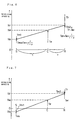
- the relationship between the revolving speed and the torque of the three shafts in the planetary gear 120 (that is, the sun gear shaft 125, the ring gear shaft 126, and the planetary carrier 124) can be expressed as nomograms illustrated in Figs. 6 and 7 and solved geometrically.
- the relationship between the revolving speed and the torque of the three shafts in the planetary gear 120 may also be analyzed numerically through calculation of energies of the respective shafts, without using the nomograms. For the clarity of explanation, however, the nomograms are used in this embodiment.
- a coordinate axis S of the sun gear shaft 125 and a coordinate axis R of the ring gear shaft 126 are positioned on either ends of a line segment
- the engine 150 is driven at the revolving speed Ne, while the ring gear shaft 126 is driven at the revolving speed Nr.
- the revolving speed Ne of the engine 150 can thus be plotted on the coordinate axis C of the planetary carrier 124 linked with the crankshaft 156 of the engine 150, and the revolving speed Nr of the ring gear shaft 126 on the coordinate axis R of the ring gear shaft 126.
- a plane curve passing through both the points is drawn, and a revolving speed Ns of the sun gear shaft 125 is then given as the intersection of this plane curve and the coordinate axis S.
- Such a plane curve is hereinafter referred to as a dynamic collinear line.
- the revolving speed Ns of the sun gear shaft 125 can be calculated from the revolving speed Ne of the engine 150 and the revolving speed Nr of the ring gear shaft 126 according to a proportional expression given below (Equation (2)).
- Ns Nr - ( Nr - Ne ) 1+ ⁇ ⁇
- the torque Te of the engine 150 is then applied (upward in the drawing) to the dynamic collinear line on the coordinate axis C of the planetary carrier 124 functioning as a line of action.
- the dynamic collinear line against the torque can be regarded as a rigid body to which a force is applied as a vector.
- the torque Te acting on the coordinate axis C is divided into a torque Tes on the coordinate axis S and a torque Ter on the coordinate axis R.
- the equilibrium of forces on the dynamic collinear line is essential for the stable state of the dynamic collinear line.
- a torque Tm1 having the same magnitude as but the opposite direction to the torque Tes is applied to the coordinate axis S
- a torque Tm2 having the same magnitude as but the opposite direction to a resultant force of the torque Ter and the torque that has the same magnitude as but the opposite direction to the torque Tr output to the ring gear shaft 126 is applied to the coordinate axis R.
- the torque Tm1 is given by the first motor MG1, and the torque Tm2 by the second motor MG2.
- the first motor MG1 applies the torque Tm1 in reverse of its rotation and thereby works as a generator to regenerate an electrical energy Pm1, which is given as the product of the torque Tm1 and the revolving speed Ns, from the sun gear shaft 125.
- the second motor MG2 applies the torque Tm2 in the direction of its rotation and thereby works as a motor to output an electrical energy Pm2, which is given as the product of the torque Tm2 and the revolving speed Nr, as a power to the ring gear shaft 126.
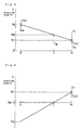
- the revolving speed Ns of the sun gear shaft 125 is positive in the nomogram of Fig. 6, it may be negative according to the revolving speed Ne of the engine 150 and the revolving speed Nr of the ring gear shaft 126 as shown in the nomogram of Fig. 7.
- the first motor MG1 applies the torque in the direction of its rotation and thereby works as a motor to consume the electrical energy Pm1 given as the product of the torque Tm1 and the revolving speed Ns.
- the second motor MG2 applies the torque in reverse of its rotation and thereby works as a generator to regenerate the electrical energy Pm2, which is given as the product of the torque Tm2 and the revolving speed Nr, from the ring gear shaft 126.
- the electrical energy Pm1 consumed by the first motor MG1 is made equal to the electrical energy Pm2 regenerated by the second motor MG2 under such conditions, all the electric power consumed by the first motor MG1 can be supplied by the second motor MG2.
- the revolving speed Nr of the ring gear shaft 126 is greater than the revolving speed Ne of the engine 150 or the revolving speed Nc of the carrier shaft 127.
- the one-way clutch 38 of the oil pressure generator 20 accordingly interlocks with the ring gear shaft 126, so that rotation of the ring gear shaft 126 drives the drive gear 30 to produce an oil pressure.
- the engine 150 is driven at the driving point of the revolving speed Ne that is lower than the revolving speed Nr of the ring gear shaft 126.
- the engine 150 may be driven at the driving point of the revolving speed Ne that is higher than the revolving speed Nr of the ring gear shaft 126 as shown in Fig. 8.
- the revolving speed Nc of the carrier shaft 127 that is connected to the crankshaft 156 of the engine 150 via the planetary carrier 124 is greater than the revolving speed Nr of the ring gear shaft 126.
- the one-way clutch 36 of the oil pressure generator 20 accordingly interlocks with the carrier shaft 127, so that rotation of the carrier shaft 127 drives the drive gear 30 to produce an oil pressure.
- the power output apparatus 110 of the embodiment may be driven only by the second motor MG2, while the engine 150 is at a stop.
- Fig. 9 shows a nomogram in this state. Since the engine 150 stops its operation, the revolving speed Ne of the engine 150 and the revolving speed Nc of the carrier shaft 127 are both equal to zero.
- the ring gear shaft 126 is, on the other hand, driven by the second motor MG2. Rotation of the ring gear shaft 126 thus enables the oil pressure generator 20 to produce an oil pressure.
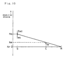
- the battery (not shown) included in the controller 180 may be charged with electric power generated by the first motor MG1, while the engine 150 is driven under the ceased condition of the vehicle.
- Fig. 10 shows a nomogram in this state.
- the revolving speed Nr of the ring gear shaft 126 is equal to zero.
- the engine 150 is, on the other hand, driven to enable the oil pressure generator 20 to produce an oil pressure through rotation of the carrier shaft 127 that is connected to the crankshaft 156 of the engine 150.
- the power output apparatus 110 of the embodiment includes the oil pressure generator 20 linked with the ring gear shaft 126 and the carrier shaft 127. As long as either one of the ring gear shaft 126 and the carrier shaft 127 rotates, the oil pressure generator 20 can produce an oil pressure. Namely when the engine 150 is driven or the vehicle moves forward, the oil pressure generator 20 can produce an oil pressure.
- the ring gear shaft 126 and the carrier shaft 127 are connected to one gear pump unit via the one-way clutches 36 and 38. This configuration reduces the size of the power output apparatus 110, compared with the structure having separate gear pump units respectively connected to the ring gear shaft 126 and the carrier shaft 127.
- the casing 22 of the oil pressure generator 20 is integrated with the case 147, to which the stator 143 of the second motor MG2 is attached.
- the oil pressure generator 20 is accordingly regarded as a large mass vibrating with the second motor MG2.
- This structure effectively damps vibrations due to the operation of the engine 150.
- the one-way clutch 36 is interlocked with the carrier shaft 127, which is an input axis of the engine 150 causing vibrations, via the interlocking member 44 that is fixed to the carrier shaft 127 across a little clearance. Even when an unexpected vibration of the engine 150 or an external turbulence causes the lost motion of the carrier shaft 127, this structure effectively absorbs the lost motion, thereby reducing inputs, such as an external turbulence, into the oil pressure generator 20.
- the one-way clutch 38 directly interlocks with the ring gear shaft 126.
- the one-way clutch 38 may interlock with an interlocking member that is fixed to ring gear shaft 126 via a little clearance. The clearance absorbs the lost motion of the ring gear shaft 126. This configuration enables the oil pressure generator 20 and thereby the power output apparatus 110 to have greater durability and higher precision.
- the oil pressure generator 20 is attached to the power output apparatus 110 having the engine 150, the planetary gear 120, the first motor MG1, and the second motor MG2.
- the oil pressure generator 20 may, however, be attached to any power output apparatus that can be driven by an engine and by a motor.
- the present invention is not restricted to the above embodiment, but there may be many modifications, changes, and alterations without departing from the scope or spirit of the main characteristics of the present invention.
- the power output apparatus is mounted on the vehicle in the above embodiment, for example, it may be mounted on other transportation means like ships and airplanes as well as a variety of industrial machines.
- An oil pressure generator 20 includes a drive gear 30, a driven gear 32, and a crescent 34, which constitute a gear pump unit, as well as one-way clutches 36 and 38 that respectively interlock with two rotating shafts 42 and 46 when the rotating shafts 42 and 46 rotate in an identical direction relative to the drive gear 30.
- the corresponding one-way clutch interlocks with the rotating shaft having a greater revolving speed, thereby driving the drive gear 30.
- This structure enables the oil pressure generator 20 to produce an oil pressure through rotation of the rotating shaft having a greater revolving speed out of the two rotating shafts 42 and 46.
Landscapes
- Engineering & Computer Science (AREA)
- Mechanical Engineering (AREA)
- Chemical & Material Sciences (AREA)
- Combustion & Propulsion (AREA)
- Transportation (AREA)
- General Engineering & Computer Science (AREA)
- Hybrid Electric Vehicles (AREA)
- Details And Applications Of Rotary Liquid Pumps (AREA)
- General Details Of Gearings (AREA)
Claims (12)
- Öldruckgenerator, der einen Öldruck erzeugt durch Antreiben eines Antriebsrads (30), das durch eine Drehkraft angetrieben wird, die an eine Eingangswelle erteilt wird, wobei der Öldruckgenerator folgendes aufweist:dadurch gekennzeichnet, dasszumindest zwei sich drehende Wellen (42, 46; 56, 58; 72, 74, 76), die unterschiedliche Drehkräfte aufnehmen; undeine Wahleinrichtung (36, 38; 52, 54; 62, 64, 66), die eine aus den zumindest zwei Drehwellen (42, 46; 56, 58; 72, 74, 76) als die Eingangswelle auswählt, wobei die Wahleinrichtung (36, 38; 52, 54; 62, 64, 66) zumindest zwei Freiläufe aufweist, die an dem Antriebsrad (30) angebracht sind und wahlweise gesperrt werden mit den Drehwellen (42, 46; 56, 58; 72, 74, 76), wobei jeder der Freiläufe die Drehkraft überträgt, wenn eine entsprechende der Drehwellen (42, 46; 56, 58; 72, 74, 76) sich in eine vorgegebene Richtung dreht, und keine Drehkraft überträgt, wenn die entsprechende der Drehwellen (42, 46; 56, 58; 72, 74, 76) sich in einer zu der vorgegebenen Richtung entgegengesetzten Richtung dreht,
das Antriebsrad (30) einen Ausschnitt bei der Mitte hat, indem die zumindest zwei Freiläufe zwischen dem Antriebsrad (30) und den Drehwellen (42, 46; 56, 58; 72, 74, 76) vorgesehen sind. - Öldruckgenerator nach Anspruch 1, wobei die zwei Drehwellen (56, 58) koaxial angeordnet sind.
- Öldruckgenerator nach Anspruch 1 oder 2, wobei die Eingangswelle und die zumindest zwei Drehwellen (42, 46; 72, 74, 76) konzentrisch sind.
- Öldruckgenerator nach einem der Ansprüche 1 bis 3, wobei das Antriebsrad (30) ein Fixierelement (40) aufweist, an dem die zumindest zwei Freiläufe angebracht sind.
- Öldruckgenerator nach einem der Ansprüche 1 bis 4, wobei ein Freilauf mit einer Drehwelle (42) sperrt über ein Sperrelement (44), das an der Drehwelle (42) fixiert ist.
- Öldruckgenerator nach Anspruch 5, wobei ein kleiner Spielraum vorgesehen ist zwischen dem Sperrelement (44) und der Drehwelle (42).
- Kraftabgabegerät, das eine Kraft an eine Antriebswelle (112) abgibt, wobei das Kraftabgabegerät folgendes aufweist:einen Verbrennungsmotor (150) mit einer Abtriebswelle (156) ;einen ersten Motor (MG1) mit einer ersten Umdrehungswelle (125), die konzentrisch mit der Verbrennungsmotorabtriebswelle (156) ist;einen zweiten Motor (MG2) mit einer zweiten Umdrehungswelle (126), die mit der Antriebswelle (112) verbunden ist und konzentrisch mit der Verbrennungsmotorabtriebswelle (156) ist;ein Planetenrad (121, 122, 124), das antriebsverbunden ist mit der Antriebswelle (112) und mit der Verbrennungsmotorabtriebswelle (156), der ersten Umdrehungswelle des ersten Motors und der zweiten Umdrehungswelle des zweiten Motors verbunden ist, wobeidas Planetenrad die Krafteinleitung und Abgabe von einer übrigen Welle bestimmt auf der Grundlage einer vorgegebenen Krafteinleitung und Abgabe von anderen zwei Wellen der Verbrennungsmotorabtriebswelle, der ersten Umdrehungswelle und der zweiten Umdrehungswelle; undeinen Öldruckgenerator (20), der durch eine Eingangswelle angetrieben wird und einen Öldruck erzeugt,wobei der Öldruckgenerator (20) folgendes aufweist:eine erste Drehwelle (42), die mit der Verbrennungsmotorabtriebswelle (156) verbunden ist,eine zweite Drehwelle (46), die mit der zweiten Umdrehungswelle verbunden ist, undeine Wahleinrichtung (36, 38), die eine der Drehwellen als die Eingangswelle wählt.
- Kraftabgabegerät nach Anspruch 7, wobei der Öldruckgenerator (20) einstückig mit dem zweiten Motor (MG2) ist.
- Kraftabgabegerät nach Anspruch 7 oder 8, wobei ein Spielraum eingerichtet ist zwischen der Verbrennungsmotorabtriebswelle (156) und der ersten Drehwelle (42).
- Kraftabgabegerät nach einem der Ansprüche 7 bis 9, wobei ein Spielraum eingerichtet ist zwischen der zweiten Umdrehungswelle (126) und der zweiten Drehwelle (46) des Öldruckgenerators (20).
- Kraftabgabegerät nach einem der Ansprüche 7 bis 10, wobei die Wahleinrichtung (36, 38) die Drehwelle mit einer größeren Drehzahl in einer vorgegebenen Richtung als die Eingangswelle wählt.
- Kraftabgabegerät nach einem der Ansprüche 7 bis 11, wobei die Wahleinrichtung (36, 38) zumindest zwei Freiläufe (36, 38) aufweist, die jeweils an den Drehwellen (42, 46) angebracht sind, wobei jeder der Freiläufe (36, 38) die Drehkraft überträgt, wenn die entsprechende der Drehwellen sich in einer vorgegebenen Richtung dreht, und keine Drehkraft überträgt, wenn die entsprechende Drehwelle sich in einer zu der vorgegebenen Richtung entgegengesetzten Richtung dreht.
Applications Claiming Priority (6)
| Application Number | Priority Date | Filing Date | Title |
|---|---|---|---|
| JP215284/96 | 1996-07-26 | ||
| JP21528496 | 1996-07-26 | ||
| JP21528496 | 1996-07-26 | ||
| JP87728/97 | 1997-03-21 | ||
| JP8772897A JP3097594B2 (ja) | 1996-07-26 | 1997-03-21 | 動力出力装置 |
| JP8772897 | 1997-03-21 |
Publications (3)
| Publication Number | Publication Date |
|---|---|
| EP0821187A2 EP0821187A2 (de) | 1998-01-28 |
| EP0821187A3 EP0821187A3 (de) | 1998-03-18 |
| EP0821187B1 true EP0821187B1 (de) | 2001-11-07 |
Family
ID=26428975
Family Applications (1)
| Application Number | Title | Priority Date | Filing Date |
|---|---|---|---|
| EP97112856A Expired - Lifetime EP0821187B1 (de) | 1996-07-26 | 1997-07-25 | Öldruckerzeuger und Antriebsanordnung |
Country Status (4)
| Country | Link |
|---|---|
| US (1) | US5993169A (de) |
| EP (1) | EP0821187B1 (de) |
| JP (1) | JP3097594B2 (de) |
| DE (1) | DE69707986T2 (de) |
Cited By (1)
| Publication number | Priority date | Publication date | Assignee | Title |
|---|---|---|---|---|
| DE10322529B4 (de) * | 2002-05-17 | 2012-03-01 | Ford Motor Co. | Öldruck-Diagnosesystem und -verfahren für ein Hybrid-Elektrofahrzeug |
Families Citing this family (48)
| Publication number | Priority date | Publication date | Assignee | Title |
|---|---|---|---|---|
| DE19810374B4 (de) * | 1998-03-10 | 2013-05-02 | Bayerische Motoren Werke Aktiengesellschaft | Hybridantrieb für ein Kraftfahrzeug |
| GB2339606B (en) * | 1998-05-22 | 2003-03-26 | Kongsberg Techmatic Uk Ltd | Dual pump drive |
| US6554088B2 (en) * | 1998-09-14 | 2003-04-29 | Paice Corporation | Hybrid vehicles |
| DE19916489C2 (de) * | 1999-04-13 | 2002-06-20 | Daimler Chrysler Ag | Hybridantrieb für Kraftfahrzeuge |
| JP3838416B2 (ja) | 2000-10-12 | 2006-10-25 | アイシン・エィ・ダブリュ株式会社 | 駆動装置 |
| DE10059423A1 (de) * | 2000-11-30 | 2002-06-13 | Bosch Gmbh Robert | Vorrichtung zum Fördern von Flüssigkeiten, insbesondere Kraftstoff |
| US6622804B2 (en) * | 2001-01-19 | 2003-09-23 | Transportation Techniques, Llc. | Hybrid electric vehicle and method of selectively operating the hybrid electric vehicle |
| JP2004529299A (ja) * | 2001-05-11 | 2004-09-24 | リカルド エムティーシー リミテッド | 改良型動力伝達機構制御装置 |
| JP3651425B2 (ja) | 2001-08-28 | 2005-05-25 | トヨタ自動車株式会社 | 動力出力装置およびこれを備えるハイブリッド自動車 |
| JP2004060590A (ja) * | 2002-07-31 | 2004-02-26 | Japan Servo Co Ltd | ローラポンプ |
| JP4202074B2 (ja) * | 2002-09-09 | 2008-12-24 | トヨタ自動車株式会社 | 車両用駆動制御装置 |
| JP4113407B2 (ja) * | 2002-09-27 | 2008-07-09 | トヨタ自動車株式会社 | 駆動ユニット |
| DE10329215A1 (de) * | 2003-06-28 | 2005-01-13 | Zf Friedrichshafen Ag | Antriebsvorrichtung für eine Getriebe-Ölpumpe und Verfahren zum Betreiben derselben |
| DE102004036505A1 (de) | 2004-07-28 | 2006-03-16 | Daimlerchrysler Ag | Antriebsstrang |
| US7494439B2 (en) * | 2004-08-26 | 2009-02-24 | Gm Global Technology Operations, Inc. | Dual drive pump with dual chain and roller clutch and method |
| FR2884766B1 (fr) * | 2005-04-26 | 2008-11-28 | Peugeot Citroen Automobiles Sa | Dispositif de transmission de puissance d'un vehicule automobile muni d'un mecanisme a roues libres entrainant une pompe a huile |
| DE102006048050A1 (de) | 2006-10-11 | 2008-04-17 | Bayerische Motoren Werke Ag | Pumpenanordnung und Verfahren zum Betreiben derselben |
| DE102007045032A1 (de) * | 2006-10-16 | 2008-04-17 | Luk Lamellen Und Kupplungsbau Beteiligungs Kg | Pumpenantriebsanordnung |
| US7753822B2 (en) * | 2006-11-02 | 2010-07-13 | Chrysler Group Llc | Transmission pump drive |
| JP4400621B2 (ja) * | 2007-01-18 | 2010-01-20 | トヨタ自動車株式会社 | 相対回転状態検知装置 |
| JP4203527B1 (ja) * | 2007-07-18 | 2009-01-07 | アイシン・エィ・ダブリュ株式会社 | ハイブリッド車両用駆動装置 |
| DE102007054808A1 (de) * | 2007-11-16 | 2009-05-20 | Robert Bosch Gmbh | Pumpenbaugruppe zur synchronen Druckbeaufschlagung von zwei Fluidkreisen |
| JP4557065B2 (ja) * | 2008-08-07 | 2010-10-06 | トヨタ自動車株式会社 | 動力伝達装置および動力伝達装置の組付け方法 |
| US8104555B2 (en) * | 2008-10-30 | 2012-01-31 | Ford Global Technologies, Llc | Electro-mechanical pump for an automatic transmission |
| JP5339606B2 (ja) | 2009-03-31 | 2013-11-13 | 本田技研工業株式会社 | ハイブリッド自動二輪車 |
| JP4981152B2 (ja) | 2010-04-20 | 2012-07-18 | トヨタ自動車株式会社 | 車両用オイルポンプ |
| JP5535020B2 (ja) * | 2010-09-29 | 2014-07-02 | 富士重工業株式会社 | 車両用駆動装置 |
| JP5654374B2 (ja) * | 2011-02-02 | 2015-01-14 | トーヨーエイテック株式会社 | オイルポンプの駆動制御装置 |
| CN102252089A (zh) * | 2011-07-07 | 2011-11-23 | 安徽江淮汽车股份有限公司 | 用于双离合器自动变速箱的油泵 |
| US9180869B2 (en) | 2011-11-11 | 2015-11-10 | Toyota Jidosha Kabushiki Kaisha | Hybrid drive system |
| JP5927628B2 (ja) * | 2011-12-27 | 2016-06-01 | ダイハツ工業株式会社 | ハイブリッド車両におけるオイルポンプ構造 |
| US8925421B2 (en) | 2012-07-06 | 2015-01-06 | Hamilton Sundstrand Corporation | Integrated drive generator gear alignment |
| US9580065B2 (en) * | 2012-07-17 | 2017-02-28 | Altigreen Propulsion Labs Private Limited | Dual-structured electric drive and power system for hybrid vehicles |
| US9441599B2 (en) | 2012-07-17 | 2016-09-13 | Altigreen Propulsion Labs Private Limited | Induction motor-permanent magnet generator tandem configuration starter-generator for hybrid vehicles |
| JP5924417B2 (ja) * | 2012-11-26 | 2016-05-25 | トヨタ自動車株式会社 | ハイブリッド車両用駆動装置 |
| ES2482869B1 (es) * | 2012-12-21 | 2015-05-12 | Universitat Politècnica De Catalunya | Bomba de engranajes compacta y estanca |
| JP6036277B2 (ja) * | 2012-12-25 | 2016-11-30 | アイシン・エィ・ダブリュ株式会社 | 車両用伝動装置 |
| FR3011878B1 (fr) * | 2013-10-16 | 2018-01-05 | PSA Automobiles | Groupe motopropulseur pour vehicule hybride, disposant d'un generateur entrainant des machines tournantes accessoires |
| CN104309464A (zh) * | 2014-10-28 | 2015-01-28 | 中国第一汽车股份有限公司 | 一种采用单向离合器的混合动力系统 |
| CN104728416A (zh) * | 2015-03-27 | 2015-06-24 | 合肥工业大学 | 一种改进油泵布置结构的双离合变速器 |
| JP6576760B2 (ja) * | 2015-09-24 | 2019-09-18 | Ntn株式会社 | オイルポンプ駆動装置 |
| JP6570445B2 (ja) * | 2015-12-24 | 2019-09-04 | Ntn株式会社 | オイルポンプ駆動装置 |
| WO2018031016A1 (en) * | 2016-08-11 | 2018-02-15 | Gkn Driveline North America, Inc. | Vehicle torque transmission device with clutch lubrication control |
| JP6852889B2 (ja) * | 2017-04-25 | 2021-03-31 | 大東電機工業株式会社 | 下肢用マッサージ機 |
| DE102017110394B3 (de) * | 2017-05-12 | 2018-06-28 | Schaeffler Technologies AG & Co. KG | Elektrischer Pumpenaktuator, stufenloses Getriebe mit elektrischen Pumpenaktuator und Steuerungsverfahren für elektrischen Pumpenaktuator |
| JP7261645B2 (ja) * | 2019-04-02 | 2023-04-20 | カワサキモータース株式会社 | ハイブリッド車両 |
| WO2022120776A1 (zh) * | 2020-12-11 | 2022-06-16 | 浙江吉利控股集团有限公司 | 一种机械泵组件及车辆 |
| US12291949B2 (en) | 2023-07-20 | 2025-05-06 | Allied H2O, Inc. | Fluid lift system |
Family Cites Families (12)
| Publication number | Priority date | Publication date | Assignee | Title |
|---|---|---|---|---|
| US3699351A (en) * | 1971-08-02 | 1972-10-17 | Gen Motors Corp | Bi-modal vehicles with drive means for external or self-propulsion |
| JPS4849115A (de) * | 1971-10-20 | 1973-07-11 | ||
| JPS5030223A (de) * | 1973-07-20 | 1975-03-26 | ||
| US4502350A (en) * | 1983-10-06 | 1985-03-05 | General Motors Corporation | Pump drive mechanism |
| DE4124479C2 (de) * | 1991-07-24 | 2002-05-16 | Bayerische Motoren Werke Ag | Hybridantrieb, insbesondere für Fahrzeuge |
| JP3343660B2 (ja) * | 1992-12-10 | 2002-11-11 | 本田技研工業株式会社 | オイルポンプ駆動装置 |
| US5285111A (en) * | 1993-04-27 | 1994-02-08 | General Motors Corporation | Integrated hybrid transmission with inertia assisted launch |
| US5558173A (en) * | 1993-09-23 | 1996-09-24 | General Motors Corporation | Integrated hybrid transmission with mechanical accessory drive |
| US5558175A (en) * | 1994-12-13 | 1996-09-24 | General Motors Corporation | Hybrid power transmission |
| JP3289533B2 (ja) * | 1995-01-30 | 2002-06-10 | 株式会社エクォス・リサーチ | ハイブリッド型車両 |
| JP3364359B2 (ja) * | 1995-05-30 | 2003-01-08 | 株式会社エクォス・リサーチ | ハイブリッド型車両 |
| JPH09292013A (ja) * | 1996-04-25 | 1997-11-11 | Toyota Motor Corp | 自動変速機の変速制御装置 |
-
1997
- 1997-03-21 JP JP8772897A patent/JP3097594B2/ja not_active Expired - Fee Related
- 1997-07-15 US US08/893,094 patent/US5993169A/en not_active Expired - Lifetime
- 1997-07-25 DE DE69707986T patent/DE69707986T2/de not_active Expired - Lifetime
- 1997-07-25 EP EP97112856A patent/EP0821187B1/de not_active Expired - Lifetime
Cited By (2)
| Publication number | Priority date | Publication date | Assignee | Title |
|---|---|---|---|---|
| DE10322529B4 (de) * | 2002-05-17 | 2012-03-01 | Ford Motor Co. | Öldruck-Diagnosesystem und -verfahren für ein Hybrid-Elektrofahrzeug |
| DE10322529B9 (de) * | 2002-05-17 | 2012-08-02 | Ford Motor Co. | Öldruck-Diagnosesystem und -verfahren für ein Hybrid-Elektrofahrzeug |
Also Published As
| Publication number | Publication date |
|---|---|
| EP0821187A2 (de) | 1998-01-28 |
| US5993169A (en) | 1999-11-30 |
| JP3097594B2 (ja) | 2000-10-10 |
| EP0821187A3 (de) | 1998-03-18 |
| DE69707986D1 (de) | 2001-12-13 |
| JPH1089446A (ja) | 1998-04-07 |
| DE69707986T2 (de) | 2002-06-06 |
Similar Documents
| Publication | Publication Date | Title |
|---|---|---|
| EP0821187B1 (de) | Öldruckerzeuger und Antriebsanordnung | |
| US5904631A (en) | Dual electric motor drive with planetary gearing | |
| JP3949966B2 (ja) | ハイブリッド電気ビークル用のパワー組合せ装置 | |
| US8491431B2 (en) | Reconfigurable hybrid gear train | |
| US5603671A (en) | Three prime mover bus transmission | |
| EP1247679B1 (de) | Elektrisch variabler Antriebsstrang mit wählbaren Betriebsarten wie Eingangsverzweigung, Mischverzweigung, neutral und rückwärts | |
| US7282003B2 (en) | Powertrain including input disconnect and accessory drive system for an electrically variable transmission | |
| US6962545B2 (en) | Multi-range parallel-hybrid continuously variable transmission | |
| US7416501B2 (en) | Single range electrically variable transmission with lockup clutch and method of operation | |
| US7367910B2 (en) | One-mode input-split electro-mechanical transmission with two fixed speed ratios | |
| US7220200B2 (en) | Electrically variable transmission arrangement with spaced-apart simple planetary gear sets | |
| US20070099738A1 (en) | Electrically variable transmission with input split mode and compound split modes | |
| EP1526027A2 (de) | Antriebsstrang eines Kraftfahrzeuges mit elektrischem Antriebsmotor | |
| KR20010083937A (ko) | 자동차용 하이브리드 변속기 | |
| US7220202B2 (en) | Electrically variable transmission with improved gradeability | |
| CN102481925A (zh) | 移动装置 | |
| JP2000094973A (ja) | 変速装置およびそれを用いたハイブリッド車 | |
| KR101428079B1 (ko) | 차량의 하이브리드 구동장치 | |
| US7261661B2 (en) | Parallel hybrid transmission having a single motor/generator | |
| CN102991332B (zh) | 一种反向旋转电动机械 | |
| US8585521B2 (en) | Variable ratio power-split hybrid transmission | |
| KR101002098B1 (ko) | 하이브리드 무단 변속기 및 이를 이용한 하이브리드 무단 변속 시스템 | |
| KR950004792B1 (ko) | 엔진의 시동기능을 갖춘 동력전달장치 | |
| WO2001010665A1 (en) | Drive device and vehicle using the device | |
| EP1777091A1 (de) | Getriebe |
Legal Events
| Date | Code | Title | Description |
|---|---|---|---|
| PUAI | Public reference made under article 153(3) epc to a published international application that has entered the european phase |
Free format text: ORIGINAL CODE: 0009012 |
|
| 17P | Request for examination filed |
Effective date: 19970725 |
|
| AK | Designated contracting states |
Kind code of ref document: A2 Designated state(s): DE FR GB |
|
| AX | Request for extension of the european patent |
Free format text: AL;LT;LV;RO;SI |
|
| PUAL | Search report despatched |
Free format text: ORIGINAL CODE: 0009013 |
|
| AK | Designated contracting states |
Kind code of ref document: A3 Designated state(s): AT BE CH DE DK ES FI FR GB GR IE IT LI LU MC NL PT SE |
|
| AX | Request for extension of the european patent |
Free format text: AL;LT;LV;RO;SI |
|
| AKX | Designation fees paid |
Free format text: DE FR GB |
|
| RBV | Designated contracting states (corrected) |
Designated state(s): DE FR GB |
|
| 17Q | First examination report despatched |
Effective date: 19990831 |
|
| GRAG | Despatch of communication of intention to grant |
Free format text: ORIGINAL CODE: EPIDOS AGRA |
|
| GRAG | Despatch of communication of intention to grant |
Free format text: ORIGINAL CODE: EPIDOS AGRA |
|
| GRAH | Despatch of communication of intention to grant a patent |
Free format text: ORIGINAL CODE: EPIDOS IGRA |
|
| GRAH | Despatch of communication of intention to grant a patent |
Free format text: ORIGINAL CODE: EPIDOS IGRA |
|
| GRAA | (expected) grant |
Free format text: ORIGINAL CODE: 0009210 |
|
| AK | Designated contracting states |
Kind code of ref document: B1 Designated state(s): DE FR GB |
|
| REF | Corresponds to: |
Ref document number: 69707986 Country of ref document: DE Date of ref document: 20011213 |
|
| REG | Reference to a national code |
Ref country code: GB Ref legal event code: IF02 |
|
| ET | Fr: translation filed | ||
| PLBE | No opposition filed within time limit |
Free format text: ORIGINAL CODE: 0009261 |
|
| STAA | Information on the status of an ep patent application or granted ep patent |
Free format text: STATUS: NO OPPOSITION FILED WITHIN TIME LIMIT |
|
| 26N | No opposition filed | ||
| REG | Reference to a national code |
Ref country code: GB Ref legal event code: 746 Effective date: 20060103 |
|
| REG | Reference to a national code |
Ref country code: FR Ref legal event code: PLFP Year of fee payment: 20 |
|
| PGFP | Annual fee paid to national office [announced via postgrant information from national office to epo] |
Ref country code: FR Payment date: 20160613 Year of fee payment: 20 |
|
| PGFP | Annual fee paid to national office [announced via postgrant information from national office to epo] |
Ref country code: DE Payment date: 20160720 Year of fee payment: 20 Ref country code: GB Payment date: 20160720 Year of fee payment: 20 |
|
| REG | Reference to a national code |
Ref country code: DE Ref legal event code: R071 Ref document number: 69707986 Country of ref document: DE |
|
| REG | Reference to a national code |
Ref country code: GB Ref legal event code: PE20 Expiry date: 20170724 |
|
| PG25 | Lapsed in a contracting state [announced via postgrant information from national office to epo] |
Ref country code: GB Free format text: LAPSE BECAUSE OF EXPIRATION OF PROTECTION Effective date: 20170724 |