EP0821202A1 - Wärmedämmplatte für einen Boden mit Heizungs- und/oder Kühlungsanlage, Verfahrenzu ihrer Herstellung und Vorrichtung zur Durchführung des Verfahrens - Google Patents
Wärmedämmplatte für einen Boden mit Heizungs- und/oder Kühlungsanlage, Verfahrenzu ihrer Herstellung und Vorrichtung zur Durchführung des Verfahrens Download PDFInfo
- Publication number
- EP0821202A1 EP0821202A1 EP97460028A EP97460028A EP0821202A1 EP 0821202 A1 EP0821202 A1 EP 0821202A1 EP 97460028 A EP97460028 A EP 97460028A EP 97460028 A EP97460028 A EP 97460028A EP 0821202 A1 EP0821202 A1 EP 0821202A1
- Authority
- EP
- European Patent Office
- Prior art keywords
- panel
- slab
- heating
- insulation
- receive
- Prior art date
- Legal status (The legal status is an assumption and is not a legal conclusion. Google has not performed a legal analysis and makes no representation as to the accuracy of the status listed.)
- Withdrawn
Links
- 238000009413 insulation Methods 0.000 title claims abstract description 43
- 238000001816 cooling Methods 0.000 title claims abstract description 30
- 238000010438 heat treatment Methods 0.000 title claims abstract description 30
- 238000004519 manufacturing process Methods 0.000 title claims description 14
- 238000000034 method Methods 0.000 title description 5
- 239000011159 matrix material Substances 0.000 claims abstract description 14
- 230000006835 compression Effects 0.000 claims abstract description 12
- 238000007906 compression Methods 0.000 claims abstract description 12
- 239000000463 material Substances 0.000 claims abstract description 8
- 230000001413 cellular effect Effects 0.000 claims abstract description 7
- 239000012815 thermoplastic material Substances 0.000 claims abstract description 5
- 238000000465 moulding Methods 0.000 claims description 10
- 230000000295 complement effect Effects 0.000 claims description 7
- 229920001169 thermoplastic Polymers 0.000 claims description 5
- 239000004416 thermosoftening plastic Substances 0.000 claims description 4
- 239000004793 Polystyrene Substances 0.000 description 9
- 229920002223 polystyrene Polymers 0.000 description 9
- 239000011324 bead Substances 0.000 description 8
- 239000004794 expanded polystyrene Substances 0.000 description 7
- 238000009434 installation Methods 0.000 description 5
- 230000000694 effects Effects 0.000 description 3
- 230000008595 infiltration Effects 0.000 description 3
- 238000001764 infiltration Methods 0.000 description 3
- 238000002347 injection Methods 0.000 description 3
- 239000007924 injection Substances 0.000 description 3
- 238000002955 isolation Methods 0.000 description 3
- 230000000903 blocking effect Effects 0.000 description 2
- 230000007423 decrease Effects 0.000 description 2
- 239000011049 pearl Substances 0.000 description 2
- 238000003856 thermoforming Methods 0.000 description 2
- 230000004308 accommodation Effects 0.000 description 1
- 239000000853 adhesive Substances 0.000 description 1
- 230000001070 adhesive effect Effects 0.000 description 1
- 230000032683 aging Effects 0.000 description 1
- 229920003020 cross-linked polyethylene Polymers 0.000 description 1
- 239000004703 cross-linked polyethylene Substances 0.000 description 1
- 230000006870 function Effects 0.000 description 1
- 239000012212 insulator Substances 0.000 description 1
- 229920000642 polymer Polymers 0.000 description 1
- 230000001681 protective effect Effects 0.000 description 1
- 238000007789 sealing Methods 0.000 description 1
- 229910000679 solder Inorganic materials 0.000 description 1
- 125000006850 spacer group Chemical group 0.000 description 1
Images


Classifications
-
- F—MECHANICAL ENGINEERING; LIGHTING; HEATING; WEAPONS; BLASTING
- F24—HEATING; RANGES; VENTILATING
- F24D—DOMESTIC- OR SPACE-HEATING SYSTEMS, e.g. CENTRAL HEATING SYSTEMS; DOMESTIC HOT-WATER SUPPLY SYSTEMS; ELEMENTS OR COMPONENTS THEREFOR
- F24D3/00—Hot-water central heating systems
- F24D3/12—Tube and panel arrangements for ceiling, wall, or underfloor heating
- F24D3/14—Tube and panel arrangements for ceiling, wall, or underfloor heating incorporated in a ceiling, wall or floor
- F24D3/141—Tube mountings specially adapted therefor
- F24D3/142—Tube mountings specially adapted therefor integrated in prefab construction elements
-
- Y—GENERAL TAGGING OF NEW TECHNOLOGICAL DEVELOPMENTS; GENERAL TAGGING OF CROSS-SECTIONAL TECHNOLOGIES SPANNING OVER SEVERAL SECTIONS OF THE IPC; TECHNICAL SUBJECTS COVERED BY FORMER USPC CROSS-REFERENCE ART COLLECTIONS [XRACs] AND DIGESTS
- Y02—TECHNOLOGIES OR APPLICATIONS FOR MITIGATION OR ADAPTATION AGAINST CLIMATE CHANGE
- Y02B—CLIMATE CHANGE MITIGATION TECHNOLOGIES RELATED TO BUILDINGS, e.g. HOUSING, HOUSE APPLIANCES OR RELATED END-USER APPLICATIONS
- Y02B30/00—Energy efficient heating, ventilation or air conditioning [HVAC]
Definitions
- the present invention relates to an insulation slab for a floor provided with a heating and / or cooling device, a method of manufacture of such a slab and a device for implementing this process. More specifically, the invention relates to thermal and acoustic insulation of such floor.
- Heating and / or cooling floor installations include usually a load-bearing concrete floor, an insulating polystyrene slab expanded laid on said load-bearing floor, a concrete screed poured onto a device heating and / or cooling, itself placed on said insulation slab, and a floor covering placed on said screed.
- an insulation slab consisting of a panel is described. made of cellular material.
- the panel is elasticized and then machined to reveal, on one of its faces, dovetail grooves. These grooves are provided for receive studs for fixing the heating and / or cooling device.
- the first panel of said slab which is intended to be in contact with the concrete screed, present on its face provided for receiving the heating device and / or cooling a network of studs for guiding and blocking said device at the time of its installation.
- This panel is characterized by a density at least equal to 23 kg / m 3 and, preferably, greater than 28 kg / m 3 . This high density is intended to give both said first panel reduced thermal conductivity, good sealing, which results from its reduced capillarity, and good resistance to compression.
- the second panel of said slab which is intended to be in contact with the load-bearing floor, has a flat profile on its two faces. It is characterized by a density less than 15 kg / m 3 and by the elastification treatment which is applied to it before it is joined to said first panel. This treatment consists in compressing said second panel until a crushing of two thirds of its initial thickness is obtained.
- the purpose of elasticization is to reduce the dynamic rigidity of the material concerned, that is to say to make it more elastic.
- the disadvantage of this type of insulation slab is that the plate comprising the pads is not elasticized and, therefore, decreases the insulation capacity acoustic of the slab.
- the object of the present invention is to provide an insulation slab for a floor provided with a heating and / or cooling device, said slab being intended to provide thermal and acoustic insulation of said floor and being consisting of at least one panel, one of the panels having studs provided to receive said heating and / or cooling device, which is obtained by a process that is simple to implement and therefore inexpensive, while providing better insulation.
- said or each panel of the insulation slab according to the invention is elasticized.
- At least the face of said slab which is formed to receive said device is in close contact with a waterproof thermal insulating film the overlapping.
- each pad has a curved part undercut which is intended to receive said device for heating and / or cooling, which is intended to be housed between two studs adjacent.
- each stud comprises means to be able to deform towards its internal part said curved part undercut.
- said means consist of at least one obviously for example two grooves practiced so diametral on the upper face of each stud.
- the method of manufacturing an insulation slab according to the invention is such that it consists in molding in a cellular thermoplastic material, a panel of which one face has said studs, then to subject said panel to a treatment elastic compression.
- said manufacturing process consists of mold a first panel, one side of which is made of a cellular thermoplastic material comprises said studs, to mold on said first panel a second panel made of the same material as said first panel, then submit the assembly constituted by said two panels to a compression elasticization treatment.
- the first step of molding said panel or said first panel consists in molding said panel or said first panel on a thermoplastic film, so that said film has the shape of said face of the slab which is intended to receive said heating device and / or of refreshment.
- the compression device for the implementation of said treatment elasticity consists of a press comprising a die intended for compress said or each panel of the slab, the active part of said matrix having a shape complementary to that of said face of the slab which is provided to receive said heating and / or cooling device.
- said compression device comprises also a counterpress comprising a counter-matrix provided for compressing said or each panel of the slab at the same time as said matrix, the part active of said counter-matrix having a shape complementary to that of the face of the slab which is not intended to receive said heating device and / or refreshment.
- the insulation slab 1 or 1 'shown in top view in FIG. 1a is designed to support a heating and / or cooling device of the type coil, one of the straight tubular parts T of which is also shown.
- said coil is made of a material characterized by a good aging, such as cross-linked polyethylene.
- the face 3 of the slab 1, 1 ' which is designed to receive the heating and / or cooling device comprises its surface a waterproof thermal insulating film 4, for example made of polymer thermoplastic such as polystyrene.
- the slab 1 or 1 ′ has on said face 3 guide pads 5 and blocking said device during its installation which are staggered and are connected together and at their base by ribs 6.
- Said ribs 6 form squares, each square having one side in common with the square which is adjacent to it.
- each rectilinear part T of the heating and / or cooling is supported by said ribs 6 and is maintained between two adjacent alignments of studs 5.
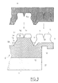
- the underside 7 of said slab 1 or 1 ′ it can have a planar shape, as in FIGS. 2 and 3, or a different profile. In the latter case, said lower face 7 may by example include ribs, grooves or pins.
- FIG. 1b The medallion is shown in FIG. 1b one of said pads 5 for above (each stud 5 has been symbolized by a simple cylinder in FIG. 1a for reasons of clarity).
- Each pad 5 has a generally frustoconical shape, as can be seen in the sectional views of Figs. 2 and 3.
- each stud 5 presents, from the base 5b of said pad 5, a linear section 5c flared towards said base 5b, which section 5c is extended by a part 5d curved towards the outside of so as to form an undercut angle for the stud 5.
- the curved parts 5d belonging respectively to two adjacent studs 5 are provided to match the contour of the rectilinear part T placed between said studs 5, so as to immobilize it.
- Said curved portion 5d is successively extended by a section linear 5e, perpendicular to said base 5b, and by a chamfer 5f, the apex of which delimits the upper face 5g of each stud 5.
- each stud 5 is parallel to the base 5b of this last and it has a generally planar shape.
- Two grooves 5h and 5i diametral and orthogonal are made on said upper face 5g, such so that their respective bottoms are located substantially at the level of the section in undercut of said curved portion 5d.
- Said grooves 5h and 5i are provided to allow the curved part 5d of each stud 5 to deform slightly towards the inside of said pad 5 during the demolding operation of the slab 1 or 1 ′.
- grooves 5h and 5i could be replaced by recesses of another type, as long as they can fulfill the same function as the grooves 5h and 5i.
- the film 4 is closely linked to said face 3 of the slab 1 or 1 ′. On the one hand, it is provided to improve the mechanical strength of said slab 1 or 1 'vis-à-vis constraints imposed on him during installation by the technician of said device between the studs 5 of the slab 1, 1 '. On the other hand, said film 4 is provided to prevent any infiltration during the subsequent pouring of the concrete screed, said infiltration being likely to create acoustic bridges in the slab 1, 1 'and therefore reduce the quality of its insulation.
- the slab 1 or 1 ′ also has in each of its upper edges 8 ledges or edges 9 and 10, which are respectively provided to secure it with the adjacent tiles.
- the respective profiles of two of said flanges 9 are shown in Figs. 2 and 3.
- FIG. 2 There is shown in FIG. 2 an insulation slab 1 corresponding to a first embodiment according to the invention.
- the insulation slab 1 consists of a single panel 2 made of polystyrene expanded molded, the side 3 of which is intended to support the heating device and / or cooling is such as that which has just been described. It is obtained from the next way.
- a film 4 made of a material waterproof thermal insulator for example a thermoplastic polymer such as polystyrene, which is subjected to a thermoforming treatment, so that it can closely match the bottom of the cavity of a mold and counter mold assembly injection, the bottom of said cavity being provided to form said face 3 of the slab 1.
- a thermoplastic polymer such as polystyrene
- the film 4 and the panel 2 are in close contact with each other.
- the aforementioned shape of the studs 5 is particularly good adapted to allow demoulding of the slab 1 in good conditions.
- the blockage induced by the section undercut of each curved part 5d disappears under the effect of the slight deformation thereof inward, which is authorized by the grooves 5h and 5i.
- the parts of it which are respectively complementary to said curved parts 5d slides on the two sections 5e and 5f of each stud 5.
- each pad 5 is intact and resumes its initial form, which is intended for the subsequent accommodation and immobilization of tubes T of the heating and / or cooling device.
- the expansion of the beads is such that the density of the molded polystyrene is close to 15 kg / m 3 .
- the next step in the manufacturing process for slab 1 is to submit the panel 2 molded on the film 4 to an elastification treatment.
- a hydraulic or mechanical press die 11 designed to apply a force F on said panel 2 and which is shown diagrammatically in FIG. 2.
- the active part 11a of the matrix 11 that is to say its face lower in this embodiment, has a shape complementary to that of the upper face 3 of the panel 2 covered with the film 4.
- the matrix 11 is provided to compress the panel 2 by exerting a pressure on its upper face and in a direction perpendicular to it.
- This elastification treatment has the effect of wrinkling the surface of the pearls. expanded polystyrene by crushing the panel 2, which results in a reduction of the rigidity of the polystyrene frame and allows better use of air trapped in panel 2, the latter being made more elastic.
- said treatment is such that the studs 5 do not show any deformation following the subsequent relaxation of the panel 2, their height not being modified during the crash.
- the slab 1 according to the invention on the surface of which are formed the studs 5 does not have to be constituted by a panel 2 of mass high volume, like the upper panel of known insulation slabs which is topped with studs, said upper panel being provided dense enough to have the required qualities of tightness and robustness, in particular.
- the film 4 which covers the upper face 3 of the panel 2 presents the two aforementioned characteristics, which makes it possible to be free from this density constraint high for panel 2 comprising said studs 5.
- the density in the region of 15 kg / m 3 which characterizes the panel 2 and the undercut part 5d that the studs 5 of said panel 2 have, are likely to cause tearing of said studs 5, during the installation of the heating and / or cooling device by the operator.
- grooves 5h and 5i are provided on the pads 5 to allow them to resume their initial shape after deformation and, on the other hand, a film 4 which covers said pads 5 for the stiffen and give them satisfactory resistance to compressive forces.
- the pads 5 covered with the film 4 do not deform following the elastification treatment, despite their reduced density.
- FIG. 3 There is shown in FIG. 3 an insulation slab 1 'corresponding to a second embodiment of the invention.
- the slab 1 ' consists of a first molded panel 12, which is covered a protective film 4 in accordance with the first embodiment of the invention, and a second panel 22 also molded but substantially shaped flat and which is secured to the underside 17 of said first panel 12 in overlay.
- Said first molded panel 12 differs from panel 2 described in the first embodiment by the value of its density, which is for example of the order of 30 kg / m 3 . Its face 3 which is designed to receive the heating and / or cooling device has the same geometry as that mentioned above.
- the slab 1 ' is preferably obtained in the following manner.
- the film 4 is placed at the bottom of the cavity of an injection mold such as as the one just described, and we inject expanded polystyrene beads on said film 4 so as to form said first panel 12, which is in contact narrow on its face 3 with the film 4.
- the expansion of said beads can be such that the density of the molded polystyrene is close to 15 kg / m 3 .
- the next step in the manufacturing process for slab 1 ' consists in subjecting the assembly of the two panels 12 and 22 to an elastification treatment.
- a press is used, the die 11 of which is identical to that shown in FIG. 2.
- the crushing and relaxation of the panels 12 and 22 is carried out in the manner previously described.
- This elastification treatment has the effect of wrinkling the surface of the pearls.
- polystyrene of the two panels 12 and 22 which results in a reduction of the rigidity of the polystyrene frame and allows better use of the trapped air in the two panels 12 and 22 of the slab 1 ', the latter being made more uniformly elastic.
- the pads 5 are not affected by the elasticization treatment, the withdrawal of the die 11 from the press does not modify not their shape.
- each panel 12, 22 being obtained by molding, and the assembly constituted by the two panels 12 and 22 being elasticized.
- the film 4 improves, on the one hand, the mechanical strength of the slab 1 'and, secondly, its sound insulation by preventing infiltration into said slab 1 ', as indicated in the first embodiment.
- the slab 1 'corresponding to the second embodiment according to the invention may not have a film 4 intimately linked to the panel 12.
- said or each panel 12 of the slab 1 ' would be obtained by a molding process before being elasticized.
- the elastification treatment applied to the slab 1 or 1 ' could also be done through a counter press with a counter-matrix (not shown), which would be intended to be applied in same time as said matrix 11 under said face 7 of the slab 1, 1 'which is not designed to receive the heating and / or cooling device.
- the active part of said counter-matrix would have a shape complementary to that of said face 7.
Landscapes
- Engineering & Computer Science (AREA)
- Physics & Mathematics (AREA)
- Thermal Sciences (AREA)
- Chemical & Material Sciences (AREA)
- Combustion & Propulsion (AREA)
- Mechanical Engineering (AREA)
- General Engineering & Computer Science (AREA)
- Casting Or Compression Moulding Of Plastics Or The Like (AREA)
Applications Claiming Priority (2)
| Application Number | Priority Date | Filing Date | Title |
|---|---|---|---|
| FR9609542 | 1996-07-24 | ||
| FR9609542A FR2751680B1 (fr) | 1996-07-24 | 1996-07-24 | Dalle d'isolation pour un plancher pourvu d'un dispositif de chauffage et/ou de rafraichissement, procede de fabrication d'une telle dalle et dispositif pour la mise en oeuvre de ce procede |
Publications (1)
| Publication Number | Publication Date |
|---|---|
| EP0821202A1 true EP0821202A1 (de) | 1998-01-28 |
Family
ID=9494603
Family Applications (1)
| Application Number | Title | Priority Date | Filing Date |
|---|---|---|---|
| EP97460028A Withdrawn EP0821202A1 (de) | 1996-07-24 | 1997-07-23 | Wärmedämmplatte für einen Boden mit Heizungs- und/oder Kühlungsanlage, Verfahrenzu ihrer Herstellung und Vorrichtung zur Durchführung des Verfahrens |
Country Status (2)
| Country | Link |
|---|---|
| EP (1) | EP0821202A1 (de) |
| FR (1) | FR2751680B1 (de) |
Cited By (2)
| Publication number | Priority date | Publication date | Assignee | Title |
|---|---|---|---|---|
| EP1104875A1 (de) * | 1999-11-30 | 2001-06-06 | Roth Werke GmbH | Dämmelement zum Verlegen von Heizungsrohren für Fussbodenheizungen |
| EP1074793A3 (de) * | 1999-08-04 | 2002-11-27 | Uponor Rohrsysteme GmbH | Noppenplatte für eine Fussbodenheizung |
Citations (4)
| Publication number | Priority date | Publication date | Assignee | Title |
|---|---|---|---|---|
| DE2840149A1 (de) * | 1978-09-15 | 1980-03-27 | Siegmund Helmut Dieter Ing Gra | Verbundplatte fuer fussbodenheizungen |
| EP0473057A1 (de) | 1990-08-31 | 1992-03-04 | Neste Oy | Heizelement für eine Fussbodenheizung |
| DE9109764U1 (de) * | 1991-08-07 | 1992-12-10 | 2H Kunststoff GmbH, 4434 Ochtrup | Halte- und Distanzierungssystem für strangförmige Bauteile, insbesondere Rohre oder Schläuche |
| FR2717519A1 (fr) | 1994-03-21 | 1995-09-22 | Isobox Technologies | Dalles d'isolation thermique et phonique et procédé de réalisation de telles dalles. |
-
1996
- 1996-07-24 FR FR9609542A patent/FR2751680B1/fr not_active Expired - Fee Related
-
1997
- 1997-07-23 EP EP97460028A patent/EP0821202A1/de not_active Withdrawn
Patent Citations (4)
| Publication number | Priority date | Publication date | Assignee | Title |
|---|---|---|---|---|
| DE2840149A1 (de) * | 1978-09-15 | 1980-03-27 | Siegmund Helmut Dieter Ing Gra | Verbundplatte fuer fussbodenheizungen |
| EP0473057A1 (de) | 1990-08-31 | 1992-03-04 | Neste Oy | Heizelement für eine Fussbodenheizung |
| DE9109764U1 (de) * | 1991-08-07 | 1992-12-10 | 2H Kunststoff GmbH, 4434 Ochtrup | Halte- und Distanzierungssystem für strangförmige Bauteile, insbesondere Rohre oder Schläuche |
| FR2717519A1 (fr) | 1994-03-21 | 1995-09-22 | Isobox Technologies | Dalles d'isolation thermique et phonique et procédé de réalisation de telles dalles. |
Cited By (2)
| Publication number | Priority date | Publication date | Assignee | Title |
|---|---|---|---|---|
| EP1074793A3 (de) * | 1999-08-04 | 2002-11-27 | Uponor Rohrsysteme GmbH | Noppenplatte für eine Fussbodenheizung |
| EP1104875A1 (de) * | 1999-11-30 | 2001-06-06 | Roth Werke GmbH | Dämmelement zum Verlegen von Heizungsrohren für Fussbodenheizungen |
Also Published As
| Publication number | Publication date |
|---|---|
| FR2751680B1 (fr) | 1999-04-30 |
| FR2751680A1 (fr) | 1998-01-30 |
Similar Documents
| Publication | Publication Date | Title |
|---|---|---|
| EP0428885B1 (de) | Verfahren zur Herstellung eines Skis durch Injektion, und Skistruktur | |
| EP0650620B1 (de) | Verfahren zur herstellung einer karte, die mindestens einen elektronischen baustein enthält,und nach einem solchen verfahren hergestellte karte | |
| EP0794051A1 (de) | Form für eine gestapelte Mehrschichtstruktur | |
| EP0309325A1 (de) | Verfahren zum Giessen eines Rahmens auf eine Polsterung zur Herstellung eines Sitzelementes | |
| FR2651171A1 (fr) | Procede et dispositif de fabrication de moulure de cote de caisse de vehicule a partir de matiere thermoplastique extrudee, par refaconnage par compression a chaud dans un moule et bande obtenue. | |
| EP0821202A1 (de) | Wärmedämmplatte für einen Boden mit Heizungs- und/oder Kühlungsanlage, Verfahrenzu ihrer Herstellung und Vorrichtung zur Durchführung des Verfahrens | |
| FR2852339A1 (fr) | Plaque a sol equipee de plots de retenue de tubes de chauffage ou de refroidissement par le sol | |
| EP0251959A1 (de) | Verfahren zum Herstellen von aus Polyurethanschaum geformten Polstern mit mehreren Zonen verschiedener Nachgiebigkeit und danach hergestellte Polster | |
| EP1421978B1 (de) | Gleitbrett and sein Herstellungsverfahren | |
| EP1008317A1 (de) | Sitzkissen, insbesondere für Kraftfahrzeuge, und Verfahren zu dessen Herstellung | |
| EP0070770A1 (de) | Vorrichtung zur Auflage eines Fussbodens auf einer Mauer und Konstruktionsverfahren hierfür | |
| FR2868980A1 (fr) | Procede de fabrication d'une piece composite et piece composite correspondante | |
| EP0729769A1 (de) | Verfahren zur Herstellung einer Spritzgussstruktur | |
| CA2039675A1 (fr) | Moule pour le moulage de pieces en matiere plastique, et son procede de fabrication | |
| FR2507647A1 (fr) | Panneau de construction prefabrique et procede pour la realisation d'un tel panneau | |
| EP0629482B1 (de) | Umgossene Verglasung und Vorrichtung zu deren Herstellung | |
| EP1226923B1 (de) | Verstärktes elastomerfolienartiges mechanisches Werkstück, Verfahren und Formwerkzeug zu dessen Herstellung | |
| EP0733738A1 (de) | Herstellungsverfahren für eine Eisenbahnschienenunterstützung und nach dem Verfahren hergstellte Unterstützung | |
| EP0786380A1 (de) | Paneel,insbesondere für Innenverkleidung von Kraftfahrzeugtüren mit mindestens einemlokalen aesthetischen Bereich | |
| EP0695616B1 (de) | Verfahren zum Herstellen von Kunststoffengegenständen mit einem festen Teil und einem weichen Schaumstoffteil | |
| FR2890893A1 (fr) | Piece de vehicule automobile comprenant une ame alveolaire et une peau | |
| EP0512874B1 (de) | Distanzplatte für die Herstellung von gross dimensionierten Platten aus Faserzement, das Herstellungsverfahren und die Form | |
| FR2597907A2 (fr) | Parpaing isolant par l'exterieur | |
| EP2127845B1 (de) | Verbessertes Herstellungsverfahren eines Teils, das eine Armstütze mit Komfortüberzug bildet | |
| FR2717519A1 (fr) | Dalles d'isolation thermique et phonique et procédé de réalisation de telles dalles. |
Legal Events
| Date | Code | Title | Description |
|---|---|---|---|
| PUAI | Public reference made under article 153(3) epc to a published international application that has entered the european phase |
Free format text: ORIGINAL CODE: 0009012 |
|
| AK | Designated contracting states |
Kind code of ref document: A1 Designated state(s): AT BE CH DE DK ES FI FR GB GR IE IT LI LU MC NL PT SE |
|
| 17P | Request for examination filed |
Effective date: 19980217 |
|
| RBV | Designated contracting states (corrected) |
Designated state(s): AT DE ES FR GB IT |
|
| 17Q | First examination report despatched |
Effective date: 19991210 |
|
| GRAG | Despatch of communication of intention to grant |
Free format text: ORIGINAL CODE: EPIDOS AGRA |
|
| GRAG | Despatch of communication of intention to grant |
Free format text: ORIGINAL CODE: EPIDOS AGRA |
|
| GRAH | Despatch of communication of intention to grant a patent |
Free format text: ORIGINAL CODE: EPIDOS IGRA |
|
| STAA | Information on the status of an ep patent application or granted ep patent |
Free format text: STATUS: THE APPLICATION IS DEEMED TO BE WITHDRAWN |
|
| 18D | Application deemed to be withdrawn |
Effective date: 20010323 |