EP0821212A2 - Wärmeaustauscher - Google Patents
Wärmeaustauscher Download PDFInfo
- Publication number
- EP0821212A2 EP0821212A2 EP97109258A EP97109258A EP0821212A2 EP 0821212 A2 EP0821212 A2 EP 0821212A2 EP 97109258 A EP97109258 A EP 97109258A EP 97109258 A EP97109258 A EP 97109258A EP 0821212 A2 EP0821212 A2 EP 0821212A2
- Authority
- EP
- European Patent Office
- Prior art keywords
- heat exchange
- exchange tubes
- tube
- heat exchanger
- area
- Prior art date
- Legal status (The legal status is an assumption and is not a legal conclusion. Google has not performed a legal analysis and makes no representation as to the accuracy of the status listed.)
- Granted
Links
- 238000010079 rubber tapping Methods 0.000 claims description 11
- 239000012809 cooling fluid Substances 0.000 claims description 4
- XLYOFNOQVPJJNP-UHFFFAOYSA-N water Substances O XLYOFNOQVPJJNP-UHFFFAOYSA-N 0.000 abstract description 4
- 238000004804 winding Methods 0.000 abstract 2
- 239000012530 fluid Substances 0.000 abstract 1
- 239000007789 gas Substances 0.000 description 5
- 230000008878 coupling Effects 0.000 description 1
- 238000010168 coupling process Methods 0.000 description 1
- 238000005859 coupling reaction Methods 0.000 description 1
- 239000000428 dust Substances 0.000 description 1
- 229920001971 elastomer Polymers 0.000 description 1
- 239000005060 rubber Substances 0.000 description 1
- 230000001960 triggered effect Effects 0.000 description 1
Images

Classifications
-
- F—MECHANICAL ENGINEERING; LIGHTING; HEATING; WEAPONS; BLASTING
- F28—HEAT EXCHANGE IN GENERAL
- F28D—HEAT-EXCHANGE APPARATUS, NOT PROVIDED FOR IN ANOTHER SUBCLASS, IN WHICH THE HEAT-EXCHANGE MEDIA DO NOT COME INTO DIRECT CONTACT
- F28D7/00—Heat-exchange apparatus having stationary tubular conduit assemblies for both heat-exchange media, the media being in contact with different sides of a conduit wall
- F28D7/08—Heat-exchange apparatus having stationary tubular conduit assemblies for both heat-exchange media, the media being in contact with different sides of a conduit wall the conduits being otherwise bent, e.g. in a serpentine or zig-zag
- F28D7/082—Heat-exchange apparatus having stationary tubular conduit assemblies for both heat-exchange media, the media being in contact with different sides of a conduit wall the conduits being otherwise bent, e.g. in a serpentine or zig-zag with serpentine or zig-zag configuration
- F28D7/085—Heat-exchange apparatus having stationary tubular conduit assemblies for both heat-exchange media, the media being in contact with different sides of a conduit wall the conduits being otherwise bent, e.g. in a serpentine or zig-zag with serpentine or zig-zag configuration in the form of parallel conduits coupled by bent portions
-
- F—MECHANICAL ENGINEERING; LIGHTING; HEATING; WEAPONS; BLASTING
- F28—HEAT EXCHANGE IN GENERAL
- F28D—HEAT-EXCHANGE APPARATUS, NOT PROVIDED FOR IN ANOTHER SUBCLASS, IN WHICH THE HEAT-EXCHANGE MEDIA DO NOT COME INTO DIRECT CONTACT
- F28D7/00—Heat-exchange apparatus having stationary tubular conduit assemblies for both heat-exchange media, the media being in contact with different sides of a conduit wall
- F28D7/08—Heat-exchange apparatus having stationary tubular conduit assemblies for both heat-exchange media, the media being in contact with different sides of a conduit wall the conduits being otherwise bent, e.g. in a serpentine or zig-zag
-
- F—MECHANICAL ENGINEERING; LIGHTING; HEATING; WEAPONS; BLASTING
- F28—HEAT EXCHANGE IN GENERAL
- F28G—CLEANING OF INTERNAL OR EXTERNAL SURFACES OF HEAT-EXCHANGE OR HEAT-TRANSFER CONDUITS, e.g. WATER TUBES OR BOILERS
- F28G7/00—Cleaning by vibration or pressure waves
Definitions
- the invention relates to a heat exchanger with numerous flowed through by a cooling fluid, approximately parallel to each other trending heat exchange tubes in one of hot gas flow channel are arranged, each Heat exchange tube is wound.
- the gases to be cooled in this type of heat exchanger often contain dust and various types of vapors that deposits and caking occur during operation form the outside of the heat exchange tubes. Such toppings heat transfer on the pipes deteriorate.
- the invention has for its object coverings and Caking on the heat exchange tubes on simple and effective way to eliminate. This is achieved according to the invention in the heat exchanger of the type mentioned in that the heat exchange tubes are stationary in the area of their turns are held and the central area of the heat exchange tubes is in contact with a tap tube between the turns, where jerky movements of the knocking tube vibrations in the Generate heat exchange tubes. Solve through the vibrations the rubbers and fall off.
- the knock pipe which vibrates in the Heat exchange tubes can be produced in various ways be trained.
- the knock pipe advantageously runs in the Area of contact with the heat exchange tubes, for example perpendicular to the heat exchange tubes. This can cause bumps intense vibrations in the knocking tube generate the heat exchange tubes.
- the knock pipe with the Heat exchange tubes is connected, but this connection is expedient to a stable arrangement even in continuous operation to have.
- the knock pipe is wound several times and designed to be elastically movable, with impacts on it Turns are transferred to the heat exchange tubes.
- the heat exchange tubes it is possible to only use the heat exchange tubes to initiate in sections.
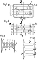
- the hot gases shown in cross section in FIG gas channel (1) with an upward flow has several inside Heat exchange tubes (2).
- a single heat exchange tube (2) visible and it is in Fig. 2nd in its form with several turns (2a), (2b) and (2c) detect. They are in the area of the turns Heat exchange tubes (2) attached to supports (3), the self are connected again with vertical support tubes (4).
- Figure 1 is the connection between the supports (3) and Heat exchange tubes (2) for better clarity not shown.
- the heat exchange tubes (2) are in Connection with collecting chambers (6) and (7) for the inlet and Removal of cooling fluid, e.g. Water vapor, water, air or oil.
- a tapping tube (8) which is shown in view in Figure 3, runs perpendicular to the heat exchange tubes (2) and is included coupled this.
- the coupling exists from tabs (9) with the tapping tube (8) and a horizontal part of a heat exchange tube are welded.
- the tabs are the better ones Not shown for clarity.
- Tabs can e.g. B. sleeves can also be used.
- both the support tubes (4) and the tapping tube (8) flowed through by cooling fluid be trained.
- the tapping tube (8) has through its tortuous shape, see FIG. 3, a certain elasticity in Direction perpendicular to the heat exchange tubes (2).
- the Knock tube is connected to a plunger (10) that goes through the wall of the channel (1) is led to the outside.
- jerky Movements of the ram (10) e.g. by blows with a Hammer, be connected to the tapping tube (8)
- Heat exchange tubes (2) perpendicular to their longitudinal axis triggered and thus set in short vibrations. This Vibrations cause the deposits on the Outside of the heat exchange tubes (2).
- the knocking tube (8) from the outside can not only be mechanical but e.g. can also be done pneumatically or electromagnetically.
- the tapping tube (8a) shown schematically in Figure 4 is wound several times and has several, led to the outside Ram (10).
- the connection of this tap tube (8a) with the associated heat exchange tubes, which are analogous to FIG. 3 is left out in Figure 4.
- tapping tube (8b) shown in FIG. 5 shows the guide of the kinked in the area of the turns (18) Tapping tube (8b).
- This shape of the turns ensures that pushing a single plunger to vibrate in the Knock pipe leads that does not affect other areas of the Knock tube are transmitted. Otherwise they have Reference numerals in Figure 5 that previously explained Meaning.
- the tapping of the heat exchange tubes according to the invention can for both horizontal and vertical flow Channels or boilers can be used.
Landscapes
- Engineering & Computer Science (AREA)
- Mechanical Engineering (AREA)
- General Engineering & Computer Science (AREA)
- Physics & Mathematics (AREA)
- Thermal Sciences (AREA)
- Chemical & Material Sciences (AREA)
- Combustion & Propulsion (AREA)
- Heat-Exchange Devices With Radiators And Conduit Assemblies (AREA)
Abstract
Description
Claims (4)
- Wärmeaustauscher mit zahlreichen, von einem Kühlfluid durchströmten, etwa parallel zueinander verlaufenden Wärmeaustauschrohren, die in einem von heißem Gas durchströmten Kanal angeordnet sind, wobei jedes Wärmeaustauschrohr gewunden ist, dadurch gekennzeichnet, daß die Wärmeaustauschrohre im Bereich ihrer Windungen ortsfest gehalten sind und der Bereich der Wärmeaustauschrohre zwischen den Windungen mit einem Klopfrohr in Berührung steht, wobei ruckartige Bewegungen des Klopfrohrs Schwingungen in den Wärmeaustauschrohren erzeugen.
- Wärmeaustauscher nach Anspruch 1, dadurch gekennzeichnet, daß das Klopfrohr im Bereich der Berührung mit den Wärmeaustauschrohren etwa senkrecht zu den Wärmeaustauschrohren verläuft.
- Wärmeaustauscher nach Anspruch 1 oder 2, dadurch gekennzeichnet, daß das Klopfrohr mit den Wärmeaustauschrohren verbunden ist.
- Wärmeaustauscher nach Anspruch 1 oder einem der folgenden, dadurch gekennzeichnet, daß das Klopfrohr mehrfach gewunden und elastisch bewegbar ausgebildet ist.
Applications Claiming Priority (2)
| Application Number | Priority Date | Filing Date | Title |
|---|---|---|---|
| DE19630482A DE19630482A1 (de) | 1996-07-27 | 1996-07-27 | Wärmeaustauscher |
| DE19630482 | 1996-07-27 |
Publications (3)
| Publication Number | Publication Date |
|---|---|
| EP0821212A2 true EP0821212A2 (de) | 1998-01-28 |
| EP0821212A3 EP0821212A3 (de) | 1998-09-16 |
| EP0821212B1 EP0821212B1 (de) | 2001-12-05 |
Family
ID=7801119
Family Applications (1)
| Application Number | Title | Priority Date | Filing Date |
|---|---|---|---|
| EP97109258A Expired - Lifetime EP0821212B1 (de) | 1996-07-27 | 1997-06-07 | Wärmeaustauscher |
Country Status (2)
| Country | Link |
|---|---|
| EP (1) | EP0821212B1 (de) |
| DE (2) | DE19630482A1 (de) |
Cited By (3)
| Publication number | Priority date | Publication date | Assignee | Title |
|---|---|---|---|---|
| CN103123243A (zh) * | 2011-11-21 | 2013-05-29 | 张建东 | 一种设有振动导热片的管式换热器结构 |
| JP2014126329A (ja) * | 2012-12-27 | 2014-07-07 | Kawasaki Heavy Ind Ltd | ダスト除去装置を備えた排熱ボイラーおよび熱交換器 |
| CN104976919A (zh) * | 2015-07-12 | 2015-10-14 | 东北电力大学 | 干–湿并列空冷凝汽器清洗系统及其清洗周期确定方法 |
Families Citing this family (2)
| Publication number | Priority date | Publication date | Assignee | Title |
|---|---|---|---|---|
| DE10131524B4 (de) * | 2001-07-02 | 2004-04-15 | Vattenfall Europe Generation Ag & Co. Kg | Heizfläche eines Dampferzeugers mit zahlreichen, von einem Kühlmedium durchströmten, etwa parallel zueinander verlaufenden Heizflächenrohren |
| CN111256098B (zh) * | 2018-11-30 | 2022-05-31 | 川崎重工业株式会社 | 导热管块、废热回收锅炉以及废热回收锅炉的施工方法 |
Family Cites Families (4)
| Publication number | Priority date | Publication date | Assignee | Title |
|---|---|---|---|---|
| US2204144A (en) * | 1935-10-31 | 1940-06-11 | Babcock & Wilcox Co | Fluid heat exchange apparatus |
| CA1012960A (en) * | 1975-09-25 | 1977-06-28 | Dominion Bridge Company | Mechanical cleaning device for boilers with gas flow containing sticky dust |
| DE2809735A1 (de) * | 1978-03-03 | 1979-09-06 | Vorkauf Heinrich | Waermetauscher mit durch vibration reinigbaren rohrtafeln |
| DE4121815C2 (de) * | 1991-07-02 | 1993-11-11 | Schmidt Sche Heissdampf | Wärmetauscher |
-
1996
- 1996-07-27 DE DE19630482A patent/DE19630482A1/de not_active Withdrawn
-
1997
- 1997-06-07 EP EP97109258A patent/EP0821212B1/de not_active Expired - Lifetime
- 1997-06-07 DE DE59705630T patent/DE59705630D1/de not_active Expired - Fee Related
Non-Patent Citations (1)
| Title |
|---|
| None |
Cited By (4)
| Publication number | Priority date | Publication date | Assignee | Title |
|---|---|---|---|---|
| CN103123243A (zh) * | 2011-11-21 | 2013-05-29 | 张建东 | 一种设有振动导热片的管式换热器结构 |
| JP2014126329A (ja) * | 2012-12-27 | 2014-07-07 | Kawasaki Heavy Ind Ltd | ダスト除去装置を備えた排熱ボイラーおよび熱交換器 |
| CN104976919A (zh) * | 2015-07-12 | 2015-10-14 | 东北电力大学 | 干–湿并列空冷凝汽器清洗系统及其清洗周期确定方法 |
| CN104976919B (zh) * | 2015-07-12 | 2017-03-15 | 东北电力大学 | 干–湿并列空冷凝汽器清洗系统及其清洗周期确定方法 |
Also Published As
| Publication number | Publication date |
|---|---|
| EP0821212B1 (de) | 2001-12-05 |
| DE59705630D1 (de) | 2002-01-17 |
| DE19630482A1 (de) | 1998-01-29 |
| EP0821212A3 (de) | 1998-09-16 |
Similar Documents
| Publication | Publication Date | Title |
|---|---|---|
| DE2008311B2 (de) | Waermetauscher | |
| DE4014415A1 (de) | Vorrichtung zur katalytischen oxidation der schaedlichen bestandteile in einem abgekuehlten traegergas eines verfahrenstechnischen prozesses | |
| DE2922841A1 (de) | Blasrohr fuer einen russblaeser | |
| EP0635694B1 (de) | Vorrichtung zum Abkühlen eines belagbildenden Gases | |
| EP0821212A2 (de) | Wärmeaustauscher | |
| DE3406893C2 (de) | ||
| DE3208421C2 (de) | ||
| DE2734031C2 (de) | Mobiler Naßdampf-Zwangsdurchlaufdampferzeuger | |
| DE3312599A1 (de) | Russblaeser zum beseitigen von ablagerungen in gasdurchstroemten raeumen, wie waermetauschern, reaktionsraeumen und dergleichen | |
| DE3538515C2 (de) | ||
| EP0518813B1 (de) | Anlage zum Kühlen von heissem, staubbeladenem Gas und Verfahren zum Betrieb der Anlage | |
| DE2822743C2 (de) | ||
| EP0203445B1 (de) | Rohgas-Reingas-Wärmetauscher | |
| DE3401606C2 (de) | ||
| DE69110640T2 (de) | Kessel mit gestütztem Wärmeübergangsbündel. | |
| DE69102879T2 (de) | Gaskühler zur wärmeübertragung durch konvektion. | |
| DE2418504C2 (de) | Rohrelement für Heizflächengruppe eines Wärmetauschers | |
| DE1009647B (de) | Roehrenwaermeaustauscher | |
| DE3446552A1 (de) | Vorrichtung zur waermerueckgewinnung und waesche von heissen, mit umweltschaedlichen verunreinigungen belasteten gasen | |
| DE2741359C2 (de) | Durch Vibration reinigbare Rohrtafel | |
| DE102024115024A1 (de) | Temperieranordnung zur Temperierung einer Sorbentschüttung, für eine Direct Air Capture Vorrichtung, Sorbentbehälteranordnung mit der Temperieranordnung und Direct Air Capture Vorrichtung | |
| DE19533071C2 (de) | Vorrichtung zur Reinigung von Einbauten in wärme- und/oder verfahrenstechnischen Apparaten | |
| DE1126554B (de) | Verfahren zum Betreiben eines Dampfrussblaesers fuer Taschen-Waermeaustauscher und Vorrichtung zur Durchfuehrung des Verfahrens | |
| DE3621850A1 (de) | Verfahren und einrichtung zum reinigen der innen- oder aussenwand stehender oder haengender rohre von waermetauschern | |
| DE1758267C (de) | Kuhlkamin |
Legal Events
| Date | Code | Title | Description |
|---|---|---|---|
| PUAI | Public reference made under article 153(3) epc to a published international application that has entered the european phase |
Free format text: ORIGINAL CODE: 0009012 |
|
| AK | Designated contracting states |
Kind code of ref document: A2 Designated state(s): CH DE FR GB LI |
|
| PUAL | Search report despatched |
Free format text: ORIGINAL CODE: 0009013 |
|
| AK | Designated contracting states |
Kind code of ref document: A3 Designated state(s): AT BE CH DE DK ES FI FR GB GR IE IT LI LU MC NL PT SE |
|
| RAP1 | Party data changed (applicant data changed or rights of an application transferred) |
Owner name: METALLGESELLSCHAFT AKTIENGESELLSCHAFT |
|
| 17P | Request for examination filed |
Effective date: 19990316 |
|
| AKX | Designation fees paid |
Free format text: CH DE FR GB LI |
|
| RBV | Designated contracting states (corrected) |
Designated state(s): CH DE FR GB LI |
|
| RAP1 | Party data changed (applicant data changed or rights of an application transferred) |
Owner name: MG TECHNOLOGIES AG |
|
| GRAG | Despatch of communication of intention to grant |
Free format text: ORIGINAL CODE: EPIDOS AGRA |
|
| 17Q | First examination report despatched |
Effective date: 20010404 |
|
| GRAG | Despatch of communication of intention to grant |
Free format text: ORIGINAL CODE: EPIDOS AGRA |
|
| GRAH | Despatch of communication of intention to grant a patent |
Free format text: ORIGINAL CODE: EPIDOS IGRA |
|
| GRAH | Despatch of communication of intention to grant a patent |
Free format text: ORIGINAL CODE: EPIDOS IGRA |
|
| GRAA | (expected) grant |
Free format text: ORIGINAL CODE: 0009210 |
|
| AK | Designated contracting states |
Kind code of ref document: B1 Designated state(s): CH DE FR GB LI |
|
| REG | Reference to a national code |
Ref country code: CH Ref legal event code: EP |
|
| REG | Reference to a national code |
Ref country code: GB Ref legal event code: IF02 |
|
| REF | Corresponds to: |
Ref document number: 59705630 Country of ref document: DE Date of ref document: 20020117 |
|
| GBT | Gb: translation of ep patent filed (gb section 77(6)(a)/1977) |
Effective date: 20020307 |
|
| ET | Fr: translation filed | ||
| PLBE | No opposition filed within time limit |
Free format text: ORIGINAL CODE: 0009261 |
|
| STAA | Information on the status of an ep patent application or granted ep patent |
Free format text: STATUS: NO OPPOSITION FILED WITHIN TIME LIMIT |
|
| 26N | No opposition filed | ||
| REG | Reference to a national code |
Ref country code: CH Ref legal event code: PUE Owner name: LENTJES GMBH Free format text: MG TECHNOLOGIES AG#BOCKENHEIMER LANDSTRASSE 73-77#60325 FRANKFURT AM MAIN (DE) -TRANSFER TO- LENTJES GMBH#DANIEL-GOLDBACH-STRASSE 19#40880 RATINGEN (DE) |
|
| REG | Reference to a national code |
Ref country code: GB Ref legal event code: 732E |
|
| REG | Reference to a national code |
Ref country code: FR Ref legal event code: TP Ref country code: FR Ref legal event code: CD |
|
| PGFP | Annual fee paid to national office [announced via postgrant information from national office to epo] |
Ref country code: CH Payment date: 20080613 Year of fee payment: 12 |
|
| PGFP | Annual fee paid to national office [announced via postgrant information from national office to epo] |
Ref country code: DE Payment date: 20080620 Year of fee payment: 12 |
|
| PGFP | Annual fee paid to national office [announced via postgrant information from national office to epo] |
Ref country code: FR Payment date: 20080613 Year of fee payment: 12 |
|
| PGFP | Annual fee paid to national office [announced via postgrant information from national office to epo] |
Ref country code: GB Payment date: 20080620 Year of fee payment: 12 |
|
| REG | Reference to a national code |
Ref country code: CH Ref legal event code: PL |
|
| GBPC | Gb: european patent ceased through non-payment of renewal fee |
Effective date: 20090607 |
|
| REG | Reference to a national code |
Ref country code: FR Ref legal event code: ST Effective date: 20100226 |
|
| PG25 | Lapsed in a contracting state [announced via postgrant information from national office to epo] |
Ref country code: LI Free format text: LAPSE BECAUSE OF NON-PAYMENT OF DUE FEES Effective date: 20090630 Ref country code: FR Free format text: LAPSE BECAUSE OF NON-PAYMENT OF DUE FEES Effective date: 20090630 Ref country code: CH Free format text: LAPSE BECAUSE OF NON-PAYMENT OF DUE FEES Effective date: 20090630 |
|
| PG25 | Lapsed in a contracting state [announced via postgrant information from national office to epo] |
Ref country code: GB Free format text: LAPSE BECAUSE OF NON-PAYMENT OF DUE FEES Effective date: 20090607 |
|
| PG25 | Lapsed in a contracting state [announced via postgrant information from national office to epo] |
Ref country code: DE Free format text: LAPSE BECAUSE OF NON-PAYMENT OF DUE FEES Effective date: 20100101 |