EP0821502A2 - Liaison infra-rouge à duplex temporel - Google Patents
Liaison infra-rouge à duplex temporel Download PDFInfo
- Publication number
- EP0821502A2 EP0821502A2 EP97305528A EP97305528A EP0821502A2 EP 0821502 A2 EP0821502 A2 EP 0821502A2 EP 97305528 A EP97305528 A EP 97305528A EP 97305528 A EP97305528 A EP 97305528A EP 0821502 A2 EP0821502 A2 EP 0821502A2
- Authority
- EP
- European Patent Office
- Prior art keywords
- signals
- slowbus
- data
- messages
- audio
- Prior art date
- Legal status (The legal status is an assumption and is not a legal conclusion. Google has not performed a legal analysis and makes no representation as to the accuracy of the status listed.)
- Withdrawn
Links
Images


Classifications
-
- H—ELECTRICITY
- H04—ELECTRIC COMMUNICATION TECHNIQUE
- H04W—WIRELESS COMMUNICATION NETWORKS
- H04W88/00—Devices specially adapted for wireless communication networks, e.g. terminals, base stations or access point devices
- H04W88/02—Terminal devices
-
- H—ELECTRICITY
- H04—ELECTRIC COMMUNICATION TECHNIQUE
- H04B—TRANSMISSION
- H04B10/00—Transmission systems employing electromagnetic waves other than radio-waves, e.g. infrared, visible or ultraviolet light, or employing corpuscular radiation, e.g. quantum communication
- H04B10/11—Arrangements specific to free-space transmission, i.e. transmission through air or vacuum
- H04B10/114—Indoor or close-range type systems
- H04B10/1143—Bidirectional transmission
-
- H—ELECTRICITY
- H04—ELECTRIC COMMUNICATION TECHNIQUE
- H04B—TRANSMISSION
- H04B10/00—Transmission systems employing electromagnetic waves other than radio-waves, e.g. infrared, visible or ultraviolet light, or employing corpuscular radiation, e.g. quantum communication
- H04B10/80—Optical aspects relating to the use of optical transmission for specific applications, not provided for in groups H04B10/03 - H04B10/70, e.g. optical power feeding or optical transmission through water
- H04B10/801—Optical aspects relating to the use of optical transmission for specific applications, not provided for in groups H04B10/03 - H04B10/70, e.g. optical power feeding or optical transmission through water using optical interconnects, e.g. light coupled isolators, circuit board interconnections
-
- H—ELECTRICITY
- H04—ELECTRIC COMMUNICATION TECHNIQUE
- H04L—TRANSMISSION OF DIGITAL INFORMATION, e.g. TELEGRAPHIC COMMUNICATION
- H04L5/00—Arrangements affording multiple use of the transmission path
- H04L5/14—Two-way operation using the same type of signal, i.e. duplex
- H04L5/1469—Two-way operation using the same type of signal, i.e. duplex using time-sharing
- H04L5/1484—Two-way operation using the same type of signal, i.e. duplex using time-sharing operating bytewise
- H04L5/1492—Two-way operation using the same type of signal, i.e. duplex using time-sharing operating bytewise with time compression, e.g. operating according to the ping-pong technique
-
- H—ELECTRICITY
- H04—ELECTRIC COMMUNICATION TECHNIQUE
- H04M—TELEPHONIC COMMUNICATION
- H04M1/00—Substation equipment, e.g. for use by subscribers
- H04M1/72—Mobile telephones; Cordless telephones, i.e. devices for establishing wireless links to base stations without route selection
- H04M1/724—User interfaces specially adapted for cordless or mobile telephones
- H04M1/72403—User interfaces specially adapted for cordless or mobile telephones with means for local support of applications that increase the functionality
- H04M1/72409—User interfaces specially adapted for cordless or mobile telephones with means for local support of applications that increase the functionality by interfacing with external accessories
- H04M1/72412—User interfaces specially adapted for cordless or mobile telephones with means for local support of applications that increase the functionality by interfacing with external accessories using two-way short-range wireless interfaces
Definitions
- the present invention relates to the telephony art and more particularly to a system utilizing a wireless digital link for transmitting audio and data in full-duplex mode between a phone, e.g., a radio or mobile phone, and its accessories.
- a phone e.g., a radio or mobile phone
- the conventional system connector in a radio or mobile phone has several disadvantages. Among these are 1) small mechanical tolerances are needed for accurate positioning of the connector or accessory, 2) electrical interference is easily induced in the cables, and 3) the reliability of the connector is not good.
- a wireless or cableless link, such as an infrared (IR) link, between the mobile phone and its accessories can be used to overcome these problems.
- IR infrared
- advantages of such links are 1) alignment of the link connectors does not have to be very accurate, 2) no cables are needed, 3) lightguides can be used to connect distant devices in a noisy environment without induced interference, and 4) the data interface can be hermetically sealed.
- an IR link as compared to an RF link, needs no EMS classification, the operating range is locally limited, and a transmission does not penetrate through walls, etc.
- apparatus capable of apparent full-duplex signal transmission, comprising: conductor means for conducting input digital signals and output digital signals at a first rate; buffer means, coupled to said conductor means, for storing said input digital signals received from said conductor means at said first rate; a multiplexer, coupled to said buffer means, for reading and transmitting said input digital signals stored in said buffer means at a second rate faster than said first rate; and a media driver, coupled to said multiplexer, for converting said input digital signals transmitted by said multiplexer into signals for external transmission; and wherein: said media driver receives and converts extemally generated signals into received digital signals in a half-duplex mode with said input digital signals transmitted by said multiplexer; said multiplexer transmits said received digital signals from said media driver and stores said received digital signals in said buffer means at said second rate; said conductor means receives at said first rate said received digital signals stored in said buffer means and outputs said received digital signals as said output digital signals at said first rate; and control means for controlling said first
- Said buffer means may comprise a FIFO register.
- Said media driver may comprise one of an IR transceiver and an RF transceiver.
- apparatus for use in a system capable of audio and data transmission comprising: audio channel means for conducting input audio signals and output audio signals; slow data channel means for conducting slowbus-messages; interface means for conducting said input and output audio signals and slowbus-messages thereacross; media driver means for converting said input audio signals and slowbus-messages to audio and data signals capable of external transmission and converting received externally generated audio and data signals to output audio signals and slowbus-messages; first buffer means for storing said input and output audio signals; second buffer means for storing said slowbus-messages; multiplexing means, coupling said media driver means to said first and second buffer means in half-duplex mode, for transmitting said stored input audio signals and said stored slowbus-messages from said first and second buffer means to said media driver means at a faster transmission rate than the respective rates at which they have been stored by said first and second buffer means, and for transmitting output audio signals and slowbus-messages from said media driver means to said first and second
- a method of controlling signal transmission to appear to be full-duplex signal transmission comprising the steps of: storing input digital signals at a first rate in a buffer; reading and transmitting said input digital signals stored in said buffer at a second rate faster than said first rate; and converting said input digital signals transmitted at said second rate into signals capable of extemal transmission; receiving and converting externally generated signals into received digital signals in a half-duplex mode with said input digital signals converted in said converting step; transmitting and storing said received digital signals in said buffer at said second rate; reading out at said first rate said received digital signals stored in said buffer; and controlling said first and second rates such that the storing of input digital signals and the reading out of received digital signals are timed to appear to be in full-duplex mode.
- Said modulating may comprise one of CVSD modulation and PCM modulation.
- Said buffer may comprise a FIFO register.
- Said signals capable of external transmission and said extemally generated signals may comprise IR signals.
- a method of controlling transmission in a system capable of audio and data transmission comprising the steps of: receiving analog audio signals and data-containing slowbus-messages; providing an interface for conducting analog audio signals and data-containing slowbus-messages back and forth in first and second directions thereacross; converting said analog audio signals conducted in said first direction to digital audio signals based thereon; storing said digital audio signals in a first buffer at a first rate; storing said slowbus-messages conducted in said first direction in a second buffer at a second rate; converting digital audio signals and slowbus-messages conducted in said first direction and respectively stored in said first and second buffers to audio and data signals based thereon for extemal transmission; transmitting said stored digital audio signals and stored slowbus-messages from said first and second buffers by half-duplex multiplexing, at a third transmission rate faster than said first and second rates at which they have been stored in said first and second buffers, when converting to audio and data signals for external transmission;
- Said input analog audio signals may be modulated by one of CVSD modulation and PCM modulation.
- Embodiments of the present invention may provide a system involving a method and means for implementing a wireless, e.g., IR, link between a phone, such as a mobile phone, and its accessories or another phone to transmit audio, control, and logical signals while overcoming the prior art timing problem.
- a wireless e.g., IR
- Embodiments of the present invention may also provide a system involving a method and means that will implement such an IR link so as to make it possible to transfer full-duplex real time audio or speech using a low speed half-duplex infrared (IR) link.
- IR infrared
- Embodiments of the present invention may further provide such a system that can be additionally adapted to implement the sending of a combination of real time speech and data over a low speed IR link at the same time.
- the present invention may relate to a system embodying a method and means for providing a wireless, e.g., IR, link between a phone, such as a mobile phone, and its accessories or another phone to transmit audio, control, and logical signals between them.
- a wireless e.g., IR
- Embodiments of the present invention may make it possible to transfer full-duplex real time audio with a low speed half-duplex IR link by using a suitable system to switch "the direction" of the half-duplex channel.
- a wireless e.g., IR
- emdodiments of the present invention may provide a system that can be additionally adapted to implement the sending of a combination of real time speech and data over a low speed IR link at the same time.
- Embodiments of the invention can also be implemented using various other devices and accessories, and electrical wires may be used for transmitting signals between devices rather than IR, although IR transmission is preferred.
- a preferred embodiment of the invention involves a short distance digital IR link which is capable of data and full-duplex audio or speech transmission and that supports digital and analog phones, single accessory connection, economical accessories, lightguides, a 3 V operating voltage, and ASIC implementation. It particularly supports fast data channel (fastbus-message), slow data channel (slowbus-message), and single audio channel transfer between a mobile phone and a single accessory device, and may be embodied in an infrared link module, e.g., of a type such as disclosed in the Ser.No.08/567,634 application, which module has transmission channels for digital full-duplex audio signals, slowbus- and fastbus-messages, and for some control data.
- an infrared link module e.g., of a type such as disclosed in the Ser.No.08/567,634 application, which module has transmission channels for digital full-duplex audio signals, slowbus- and fastbus-messages, and for some control data.
- This module may be adaptable for use as an integrated part of a mobile phone and its accessories, and the same module can be used both in the phone and in an accessory device.
- the link module is connected to the baseband of the phone through a baseband interface (BBIF) and communicates through a media interface (MIF) and an infrared interface (IRIF) externally with free air space or a lightguide.
- BBIF baseband interface
- MIF media interface
- IRIF infrared interface
- a link-specific low-level protocol is used for audio and slowbus-message transmission but the link hardware of the module may also support other protocol implementations.
- the invention may be embodied in hardware or in software or both.
- Operation of the IR link in full-duplex manner is based on multiplexing/demultiplexing wherein audio and data signals from different channel buffers are converted for transmission into signals with a suitable format for infrared media through the media interface or MIF and externally generated received formatted signals are reconverted for storage in the buffers.
- the compatibility problem between real time audio transmission and limitations of the commercially available IR-transceivers wherein there is a long receiver set-up time after transmission due to the receiver saturation, requires a special signal processing method.
- This problem may be overcome in accordance with the invention by collecting the audio signals for a longer period and then sending them much faster over the IR link and also decoding them accordingly. Therefore, there is time left to change transmission direction making a full-duplex transmission possible over a half-duplex media.
- This solution involves the utilization of a FIFO buffer for holding collected audio signals and may also be applied to slowbus-messages.
- the link can be operated in two exclusive signal handling modes, one transferring audio signal and slowbus-messages and the other transferring fastbus-messages.
- one handling mode the Normal mode
- the slowbus data is multiplexed with the audio signals in one frame.
- the Fastbus mode neither the audio signal nor the slowbus-messages are transmitted, and only fastbus data is transmitted.
- the mode can be changed at any time during the link connection. A number of control bits are transferred in the transmitted signal frame and can be used for such purposes as accessory identification and the like.
- the link When inactive, the link enters into an Idle mode to save the phone battery and is activated by sending or receiving data. If the connection is lost during the transmission, the link can recover from short period interrupts and it may enter into the Idle mode when the interrupt is longer than a specified maximum recovery time.
- Figure 1 is a schematic block diagram of the functional components of a transmission link module in accordance with the present invention.
- Figure 2 illustrates a basic signal frame structure containing control field bits for controlling the state machine of the control block component of the link module of Figure 1.
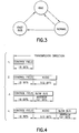
- Figure 3 illustrates the three different operation modes in which the activated link module of Figure 1 can exist, i.e., an Idle mode, a Normal mode, and a Fastbus mode.
- Figure 4 illustrates examples of possible signal frame structures in the Normal mode wherein the audio data is allocated 512 bits and the MBUS-messages are allocated anywhere from 11 bits to a maximum of 121 bits.
- Figure 5 illustrates the transitions of the state machine of the control block component of the link module shown in Figure 1.
- Figure 6 is a schematic diagram of the components of the IR-block of the link module of Figure 1.
- Figure 7 illustrates an example of the serial output of the IR-block of Figure 6 as compared to the input.
- FIG 8 is a block diagram illustrating the components on either side of the Media Interface (MIF) in the link module of Figure 1.
- MIF Media Interface
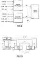
- Figure 9 illustrates data transmission across the MIF when sending (TX) and receiving (RX) data from and for the four data channels.
- Figure 10 illustrates data transmission in the Normal mode between a phone and an accessory over the transmission link.
- Figure 11 illustrates the creation of a link connection in a phone in terms of state machine steps or phases.
- Figure 12 illustrates the creation of a link connection in an accessory device in terms of state machine steps or phases.
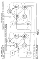
- Figure 13 illustrates the steps or phases of two consecutive cycles of one state machine for data transmission in the Normal mode.
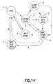
- Figure 14 illustrates the state machine steps or phases for data transmission in the Fastbus mode.
- FIG. 1 A preferred embodiment of a method and means for use in a wireless or wired system for audio (or speech or voice) and data transmission in accordance with the present invention is shown in modular form in Figure 1.
- the module or system in accordance with the invention may broadly involve a combination of functional blocks forming a transmission link and including: an audio input, e.g., a modulating device 11, such as a continuously variable slope delta (CVSD) modulator; a control block 12; a multiplexer/demultiplexer 13 (hereinafter multiplexer) which may include a processor, e.g., a digital signal processor (DSP) or RISC processor; FIFO registers 14 and 15; and a media driver 16.
- a modulating device 11 such as a continuously variable slope delta (CVSD) modulator
- CVSD continuously variable slope delta
- control block 12 e.g., a continuously variable slope delta (CVSD) modulator
- a multiplexer/demultiplexer 13 hereinafter multiplexer
- processor e
- the media driver 16 is a physical component, such as may be incorporated in a phone or an accessory, and acts to send and receive multiplexed data over the link.
- the remainder of the link can be variously implemented in hardware (HW) or software (SW), or both.
- the media driver 16 is preferably an infrared (IR) block, including a pulse shaper and transceiver, but the invention may also be implemented in other wireless or wired system designs with a different type of driver for transmission in other media.
- IR infrared
- IR link module 10 which contains the combination of functional blocks, 11 - 15, with the media driver as an IR-block 16, and which has three link interfaces associated therewith.
- the link module 10 is connected to the baseband (BB) of a host system, such as a mobile phone, through a baseband interface (BBIF) and communicates signals therefrom, through a media interface (MIF) and an infrared interface (IRIF), extemally with free space, i.e., the air (wireless), or a lightguide or other cable.
- BBIF baseband interface
- MIF media interface
- IRIF infrared interface
- the BBIF specifies how the link module 10 is connected to the host system or phone; the IRIF specifies how signals are transmitted externally between the IR-block 16 and free space or lightguides; and the MIF specifies how the blocks 11 - 15, which include the multiplexer 13, are connected to the media driver, that is, the IR-block 16.
- the three INTERFACES may be briefly defined in the following manner:
- the BBIF INTERFACE or Baseband interface specifies how the IR link module is connected to the host system (phone or accessory).
- the MIF INTERFACE or Media interface specifies how the SW-block and HW-block, which include a multiplexer/demultiplexer, are connected to a media driver.
- the IRIF INTERFACE or Infrared interface specifies how signals are transmitted back and forth externally between the IR-block and free space (air) or lightguides.
- the principle of operation briefly is based on a state machine of the control block 12 which controls the reading, writing, and multiplexing of the signal data and signal frame processing.
- the state machine is controlled by control field bits in the signal frame during reception and by incoming data during transmission, along with a few input signals, as will be described.
- the basic signal frame structure consists of a Control Field followed by a Data Field as shown in Figure 2.
- the Control Field which preferably contains 16 bits, defines the structure of the Data Field.
- the content of the Data Field can be different for different frames, but the Control and Data Fields combined preferably have a maximum of 656 bits.
- Dynamic allocation of the data structure of the frame is utilized due to the data adaptation of the link.
- the link operates on the master/slave principle where the phone is a master and an active accessory device is a slave. The accessory device can only respond to the master, and the link must be opened by the master. However, a slave originated transmission is possible.
- the link is active when the IR module blocks are useable, that is, when the circuits are powered and software is running, and data exchange between the phone, across BBIF, and an accessory, across IRIF, could occur at any time.
- the link is deactivated data exchange is not possible.
- HW-implementation HWIM
- the link In the Normal mode the link sends and receives control and digital audio data and slowbus-messages over the MIF.
- the data is transferred only when it exists and therefore the frame structure can change during transmission. Examples of possible frame structures in this mode are illustrated in Figure 4 wherein the audio signals are allocated 512 bits and the slowbus-messages anywhere from 11 bits to a maximum of 121 bits.
- the link sends and receives fastbus-messages directly to and from the multiplexer or processor over the MIP and no low level frame is used.
- the protocol is defined with the software of the processor, e.g., a digital signal processor (DSP) or a von Neuman or a RISC processor, and therefore various protocols can be used.
- DSP digital signal processor
- a von Neuman or a RISC processor
- the IR link module of the invention contains the following combination of LINK BLOCKS.
- the CVSD modulator 11 is used for analog audio signal processing to support analog phones and simple accessories. It compares the consecutive analog samples received on audio channel 17 and outputs 1 (ONE) if the value of the new sample is higher than the value of the previous one, or 0 (ZERO) if it is lower. The sampling frequency must be much higher than the upper limit of the transmitted audio band.
- This hardware block is simulated in the altemate implementation wherein the FIFOs, multiplexer, and control block are implemented in the processor software.
- Other modulation than CVSD modulation may be used, such as PCM modulation, and, in the event that the audio signals are already digitized, the audio may be put directly into the audio FIFO buffer 14.
- the serial FIFO buffers 14 and 15 are used to temporarily store data in the audio and the slow data channels, 17 and 18.
- Data to be transmitted is first slowly written into the audio FIFO 14, e.g., at a 38.4 kbits/s sampling rate, by the CVSD modulator 11, and into the slowbus FIFO 15 by the slow data channel 18, e.g., at 9.6 kbits/s, and then later read and sent to the IR-block 16 at a higher rate during transmission.
- the incoming data is placed at a high rate into the FIFOs, 14, 15, and then read with a lower rate and sent via the CVSD modulator 11 to the audio channel 17, and the slow data channel 18 respectively.
- the reading and writing is controlled by the control block 12.
- the size of the AUDIO buffer 14 is selected so that when the buffer is full the data will be transmitted.
- the modular sampling frequency is selected so that the AUDIO buffer 14 cannot overflow.
- the slowbus or slow data channel buffer 15 has a counter which counts the number of bytes stored in the buffer. This number is placed in the Control Field of the signal frame and transferred via the link. The receiving link fills the slowbus buffer 15 according to this number.
- the slowbus-messages are processed as bytes and only whole bytes are transferred.
- the slow data channel-protocol defined by the host system, takes care of processing of the slowbus-frames.
- Multiplexer 13 is used to select a data channel for reading and writing during different locations in the frame.
- the multiplexer 13 is controlled by the state machine of control block 12 and selects the right number of bits from the FIFOs 14 and 15.
- the multiplexer 13 routes the fastbus-messages from the fast data channel 19 directly to the IR-block 16.
- the signals and data are processed by a suitable processor unit, such as, for example, a digital signal processor (DSP).
- DSP digital signal processor
- Other processors such as a von Neuman or a RISC processor also may be used in implementing this function.
- Control block 12 is used to control the operation of the link.
- the operation of the control block 12 is based in a state machine which controls processing of the frame and data transfer between IR-block 16 and BBIF.
- Figure 5 illustrates the state machine transitions which will be described in detail below.
- the IR-block 16 as shown in Figure 6, consists of two components, an IR-transceiver 20 and a pulse shaper 21.
- Commercially available IR-transceiver components may be used in this application so that the physical layer of the link may be made compatible with the IrDA standard.
- the IR-block 16 and multiplexer 13 are connected through the media interface MIF.
- the wavelength of the IR radiation is typically 850-900 mm, the maximum transmission speed is 115.2 kbits/s in one direction, and the optical link length is about I meter.
- the IR-transceiver 20 components include an IR-LED and its driver, a reception detector, a receiver, and a backlight compensation circuit. Normally only half-duplex operation is possible due to the reflections in the open space which cause receiver saturation.
- the IrDA specifications require that the bit length must be narrowed to a fraction of 3/16 of the normal bit length and that only 0 (ZERO) bits are sent. By sending only narrowed 0 (ZERO) bits power will be saved and the probability of bit errors will be reduced. Also, the IR-LED current can be increased making the operating range longer due to improved radiation power.
- An example of the serial output of the IR-block 16 as compared to the input is shown in Figure 7.
- Operation of the IR module link is based on multiplexing data from the different channel buffers and converting it into a suitable format for infrared media and reconverting it upon receipt.
- the compatibility problem between real time audio transmission and limitations of the commercially available IR-transceivers requires a special signal processing method.
- the main problem is the long receiver set-up time after transmission due to the receiver saturation.
- the present invention overcomes this problem using the following solution.
- the audio data is collected for a longer period and then sent much faster over the link and decoded accordingly. Therefore, there is time left to change transmission direction making a full-duplex transmission possible over a half-duplex media.
- This solution involves the use of FIFO buffers for holding collected signals and data. In the Normal mode the slowbus data is multiplexed with the audio data in one signal frame. In the Fastbus mode the audio signal or slowbus-messages are not transmitted.
- Control of the transmissions is essentially accomplished by the control block 12 in Figure 1, the operation of which is based on a state machine that controls reading, writing and multiplexing of the data and frame processing.
- the state machine the transitions of which are shown in Figure 5, is controlled by Control Field bits in the signal frame (see Figures 2 and 4) and a few input signals.
- the Control Field bits are set when data exists in the buffers or FIFOs 14 and 15. For example, the slowbus bit is set when slowbus data exists in the slowbus buffer 15, but is reset otherwise.
- the output of the state machine selects the proper channel of the multiplexer 13 among the four.
- the Control Field is sent over the link and it controls the decoding of the frame during reception.
- the other input signals select how the state machine operates.
- one signal selects the role between the master or slave device.
- Table A shows the states and functions of the state machine of Figure 5.
- processing means either coding or decoding of the data during transmission or reception.
- the same state machine is used for receiving and transmitting the frames in a mobile phone and in an accessory device.
- CONTROL-DATA processes control field of the frame 3
- WAIT-START waits here until the next start bit is detected or the maximum waiting time is exceeded, during reception only 4
- AUDIO-DATA processes audio FIFO content
- SLOWBUS-DATA processes slowbus FIFO content
- WAIT-FRAME-END waits here until the next time slot begins, waiting time depends on the previous frame structure 7
- FASTBUS-DATA processes fastbus data (or other protocol from the processor, e.g., DSP, RISC, etc.)
- an analog audio signal coming through BBIF for transmission through IRIF is CVSD modulated in modulator 11 into digital form.
- data is transferred between the slow data channel and FIFO buffer 15 and the audio signals, after modulation, are transferred to FIFO buffer 14.
- the slow data channel driver 18 and CVSD modulator 11 write directly into the FIFOs 15 and 14.
- the data is only transferred between the multiplexer 13, or its processor, and IR-block 16 (state 7, FASTBUS-DATA in Figure 5).
- the procedure is the opposite.
- the extemally generated incoming signal frame is decoded by the receiving link which is controlled by the Control Field bits in the frame. While the link is connected, the two control blocks at either end send and receive one after another. First the master sends a frame and then the slave responds by sending a frame back.
- a media interface MIF
- MIP media interface protocol
- the preferred IR link module 10 has four transmission channels for digital full-duplex audio signals (17), slowbus and fastbus-messages (18, 19), and for some control data (9) and it is intended and designed to be used as an integrated part of phones and accessories.
- the link is connected to the baseband of a phone or accessory through the baseband interface (BBIF). Both the phone and accessory can operate as a transmitter and receiver.
- the transmitter sends data through the media interface (MIF) and through the IR-interface (IRIF) between a media driver 16 and a transmission path to the receiver.
- MIF media interface
- IRIF IR-interface
- the same link implementation can be used both in a phone or an accessory.
- the link operates according to the master/slave principle where a phone is a master and an active accessory is a slave. The slave can only respond to the master and the link has to be opened by the master.
- HWIM hardware based link
- SWIM software based implementation
- DSP digital signal processor
- the Media driver 16 is preferably implemented as an infrared block (the IR-block 16 shown in Figure 6) including a pulse shaper 21 and infrared transceiver 20.
- the MIF specifies in which form and how audio signals or data are transmitted between the media driver 16 and the multiplexer 13. A common requirement for both of these is that they have to be sent to the MIF in a specific form or protocol, i.e., the MIP.
- signals or data are transmitted as a bit stream in a serial form through the MIF.
- a half-duplex transmission is used over the MIF, i.e., signals or data can be transmitted in both directions, but only in one direction at one time. This requirement is dictated by the infrared transceiver 20 of the IR-block 16.
- the multiplexer 13 is used both to send signals and data and demultiplex received signals and data, and one cycle of the multiplexer sequence is so fast that a user perceives the communication as full-duplex transmission.
- Transmission can be transmitted in two modes, i.e., the Normal mode and the Fastbus mode.
- the Normal mode is used in a voice call to send and receive control, audio, and slowbus data over the link and the Fastbus mode is used in a data call for fastbus data transmission. Audio and slowbus data cannot be sent simultaneously with fastbus data, because all the capacity of the link is needed to send fastbus data.
- audio and data are transmitted using the MIP frame, but in the Fastbus mode a specific frame structure is not needed since data is transmitted directly between the fast data channel 19 and the MIF via the multiplexer 13.
- Audio and data are preferably sent over the MIF at a constant nominal data rate of 115.2 kbits/s.
- the signals could be sent at a different data rate by a phone and/or accessory, but at the lower data rate in the Normal mode audio quality may not be high enough.
- the higher data rate is not possible in the IR link module again because of the infrared transceiver component.
- Audio and slowbus data are transmitted over the link in a signal frame including a Data Field and a Control Field ( Figure 2).
- the Control Field consists of 16 control bits and the Data Field contains a maximum of 640 bits.
- a useable data rate for audio data is 38.4 kbits/s and for slowbus data is 9.6 kbits/s.
- the phone and accessory can send slowbus-messages using different data rates, but the 9.6 kbits/s data rate is preferred.
- Audio data is coded in the CVSD modulator 11 using a sigma delta modulation.
- the value of a current bit is set to 1 (ONE), it indicates that the current sample value is one step higher than the previous one.
- a 0 (ZERO) means the current value is one step lower than the previous sample value.
- the sampling frequency is 38.4 kbits/s and, as indicated in Figure 4, 512 bits are reserved for audio signals in one signal frame. It should be noted that slow data channel and fast data channel protocols take care of the data channel processing, such as the detection of transmission errors and the resending of frames, etc., which are not included in the MIP.
- the media interface protocol defines the frame structure used in audio and data transmission.
- a frame consists of three possible fields, i.e., Control, Audio, and Slowbus Fields. The contents of the frame depend on the transmitted data.
- the Control Field contains information about the structure of the frame and is read or written by the control block 12 in the HWIM and by program modules in the SWIM.
- Figure 4 illustrates all possible frame structures in the Normal mode.
- the frame is sent or received during a time slot within one cycle of the state machine.
- Time reserved for one bit can be calculated by taking an inverse of a data rate of 115.2 kbits/s, that is, 8.68 ⁇ s.
- a bit rate of 115.2 kbits/s also means that 57.6 kbits are sent in one direction during one second.
- the 16 bits of control data in the Control Field of each signal frame and the bits needed for changing the direction of transmission must be included in this number.
- the time required by the infrared transceiver 20 to change transmission direction is called latency time. According to the IrDA specification, latency time may not exceed 10 ms. In the present IR link module an infrared transceiver 20 with a latency time of 0.8 ms is preferred. A time value of 1.0 ms may be selected for calculation purposes taking a safety factor into account.
- the control of multiplexing can be performed with 16 bits and thus the Control Field includes 16 bits.
- the number of bits in the Data fields of the frame is selected according to the relationship of the data rates and the size of the FIFO registers 14 and 15. While the data rate of audio signals is four times higher than the data rate of slowbus data, all bits are transmitted at 115.2 kbits/s.
- the slowbus FIFO 15 has to be capable of storing 121 bits, because 121 bits have to be transmitted in the slow data channel or slowbus field over the MIF during one cycle of the state machine. According to the data rates relationship then, 512 bits are reserved for audio data.
- the exact number of bits for a time slot spacing or ending is calculated so that a clock signal can be easily divided from an existing clock signal.
- the Control Field is created by a sending control block.
- the bits of the field are set according to signals from different sources.
- the receiving demultiplexer (13) is controlled by this field whereby the received data is demultiplexed to outgoing channels according to the values of the bits.
- the Control Field structure is presented in the following table, Table C. Structure of the Control Field 0 1 2 3 4 5 6 7 8 9 10 11 12 13 14 15 S B MB A H D1 D2 D3 D4 C1 C2 C3 C4 R1 R2 R3
- Control Field is sent from left to right as viewed in Table C.
- Table C The abbreviations in Table C are explained in the following table, Table D, and text.
- Table D the allowed bit values are presented.
- the character “x” means that the bit value can be 0 (ZERO) or 1 (ONE). Explanations for abbreviations.
- the start bit (S) indicates the beginning of the frame and is always set to 0 (ZERO).
- ZERO When a device is ready to receive a frame, it stays in the state WAIT-START and observes the value of the line. When the bit S is detected the frame reading starts. The line is read until the whole frame is read completely whereupon one cycle of the state machine is done.
- the fastbus data bit (FB) is set to zero when a data call is selected.
- the slowbus data bit (SB) may be reserved for future applications and preferably is always set to 1 (ONE) in the present link module.
- the audio bit (A) informs the control block 12 about sending or receiving audio data. If the value is set to 0 (ZERO), the audio field is written into the frame or read from the frame. In the case where the value 1 (ONE), the state AUDIO-DATA for reading/writing audio data is passed.
- a hook signal pulse is generated.
- the hook bit (H) is set to 0 (ZERO).
- the phone receives the Control Field and it indicates that the hook bit is set to 0 (ZERO)
- the hook signal is generated in a phone.
- the device bits (D1, D2, D3, D4) identify a particular phone or accessory device.
- a mobile phone sends, at the start of connection, the Control Field to the accessory device to be connected.
- the device bits are set to 1 (ONE).
- the accessory device reacts and answers by sending a Control Field frame to the phone.
- the Control Field includes the unique device identification bits.
- the four slowbus counter bits (C1, C2, C3, C4) are used to inform the receiving control block about the number of slowbus bytes in the incoming frame structure. If all bits are set to 0 (ZERO), no slowbus bytes are read by the receiving multiplexer.
- the last three parameters (R1, R2, R3) are reserved for future use and preferably are set to 1 (ONE).
- the Audio Field preferably includes 512 bits of audio data and all 512 bits are significant.
- a value of 1 (ONE) in the bit sequence indicates that the new sample is one step higher than the previous one and a value of 0 (ZERO) indicates that it is one step lower.
- Sigma delta modulation is done by the CVSD modulator 11 in the HWIM.
- a CVSD modulator is simulated in the processor (DSP) software. In the case where audio data does not exist a bit sequence 01010101... is sent.
- the basic unit of transmitted slowbus data is a byte, which consists of 11 bits according to the following table, Table E. Bits of the Slowbus byte. 1 2 3 4 5 6 7 8 9 10 11 Start Data Data Dat Data Data Data Data Data Party Stop
- Counter bits in the Control Field of the frame are filled according to how many bytes of slowbus data are sent.
- the number of sent bytes can vary from 0 to 11 because 121 bits are reserved for slowbus data in the frame and the number of significant bits varies from 0 to 121.
- the insignificant bits are set to 1 (ONE) and are not sent by the media driver 16.
- control block including a state machine, and a multiplexer and demultiplexer, in accordance with the invention, which components function as follows in the preferred link modules.
- control block 12 depends on which of the two implementations of the link is used.
- the control block 12 In the HWIM the control block 12 is a physical component and in the SWIM it is part of program modules in the processor code. In both of these implementations the control block operation is based on that of the state machine.
- the block 12 controls the operations of the multiplexer 13 and it is controlled by the Control Field of the MIP frame during reception. During transmission it is controlled by incoming data and a few input signals from the BBIF.
- the multiplexer 13 also depends on the desired implementation.
- the multiplexer and demultiplexer is implemented in the ASIC and in the SWIM multiplexing is performed by program modules associated with the processor (DSP) as illustrated in Figure 8.
- DSP processor
- the multiplexer/demultiplexer 13 is used to both send and receive data.
- the multiplexer 13 acts to select incoming data from four possible data channels, i.e., the audio channel 17, the control channel 9, the slow data channel 18, and the fast data channel 19, and to multiplex and send data to the media driver 16 over the MIF.
- the demultiplexer 13 reads data from the MIF and demultiplexes and sends the data to the four channels.
- the multiplexer 13 has three operation modes depending on the data.
- the Fastbus and Normal modes are used in data transmission and mode Idle is used when no data transmission exists. All three possible modes of the multiplexer are shown in Figure 5.
- An Idle mode is set when the link is initialized or reset. In this mode the link is powered ON but no data transmission exists. After a specific time, e.g., 4 seconds, clocks are stopped to save power.
- a specific time e.g. 4 seconds
- clocks are stopped to save power.
- a user wants to send data he or she can select either the Normal mode or Fbus mode.
- the Idle mode is initialized again.
- the multiplexer 13 In the Normal mode , when sending control, audio, and slowbus data to the MIF, the multiplexer 13 is used to create a specific frame structure defined by the MIP. After sending the control bits, the multiplexer collects signal or data bits from the audio and slow data channels and sends these bits to the MIF. In the case of receiving data from the MIF, the demultiplexer creates an incoming frame defined by the MIP for the data input to the audio and slow data channels, 17 and 18. The control, audio, and slowbus bits from the incoming frame are demultiplexed according to the control bits, and the audio and slowbus data is generated.
- the state machine is needed to control multiplexing and demultiplexing of the data.
- the Control Field of the frame is used to control the operation of the state machine in the Normal mode during reception.
- the identical state machine is used to send and receive data in both a phone and accessory device.
- FIG. 10 illustrates data transmission in the Normal mode according to the following steps.
- the fast data channel protocol creates a connection and sends data after the mode has been selected.
- the sending of data can be ended by the user or the fast data channel protocol may take care of ending the connection.
- Figure 11 illustrates the creation of a connection in a phone in terms of state machine operation (see Figure 5 and Table A), and Figure 12 illustrates the similar creation of a connection in an accessory device.
- the sending and receiving of data is controlled by the state machine as will now be described. This operation is suitable for both a phone and an accessory device.
- FIG. 13 illustrates data transmission in the Normal mode in terms of state machine operation with control, audio, and slowbus data being transmitted.
- the Fastbus mode is set to transmit fastbus data between a phone and an accessory device.
- Fastbus data is sent directly from the processor to the MIF or from the MIF to the processor and the MIP frame structure is not used.
- the fast data channel protocol takes care of the fastbus channel frame processing such as the detection of transmission errors, resending of frames, etc.
- Figure 14 illustrates fastbus data transmission in the state machine.
- the Fastbus mode can be selected at any time, but it can be reached only in the state WAIT-FRAME-END.
- the FBUS-DATA state is changed to the IDLE state, sending of audio and/or slowbus data can continue, if the Normal mode is still active.
- connection between a mobile phone or accessory device can be lost for many reasons.
- the transmission of infrared light can be intercepted or blocked, e.g., by a hand, and the other part of the link can be powered down, etc.
- the state machine's WAIT-START state can be adapted to try to make the connection again after a specified time.
- the physical connections over the MIF are illustrated in Figure 8. As seen in Figure 8, four lines are routed from the multiplexer 13 to the media driver 16 over the MIF. Two of the lines are used in data transmission and two are needed in pulse creation and control. The same lines are implemented in both the HWIM and SWIM embodiments.
- Data is transmitted from the multiplexer 13 to the media driver 16 for external transmission via the line ir _ tx, and received extemally generated data from the media driver 16 to the multiplexer 13 is transmitted via the line ir_rx.
- the media driver 16 informs the multiplexer 13 about incoming data, detected by the detector-receiver-backlight component in the IR-transceiver 20, via the line ir_pulse.
- the line clk_1M8 is used to create pulses in the pulse shaper 21 component of the driver 16.
- the only difference between the HWIM and SWIM conceming the MIF is the source of the line clk_1M8 clock signal.
- the signal is taken from a pin of the ASIC, while in the SWIM the signal can be taken from any suitable source, e.g., from a clock generator 8.
- the requirements for signal clk_1M8 call for the clock frequency to be 1.8 MHz and the source of this signal to be synchronized with the 115.2 kHz clock to guarantee the correct functioning.
- a system or module is presented that is capable of utilizing a wired or wireless digital link which apparently transmits audio and data in full-duplex mode between a radio or mobile phone and its accessories while using a conventional half-duplex IR-transceiver.
- an RF transceiver might be substituted.
- the present invention includes any novel feature or combination of features disclosed herein either explicitly or any generalisation thereof irrespective of whether or not it relates to the claimed invention or mitigates any or all of the problems addressed.
Landscapes
- Engineering & Computer Science (AREA)
- Computer Networks & Wireless Communication (AREA)
- Signal Processing (AREA)
- Physics & Mathematics (AREA)
- Electromagnetism (AREA)
- Human Computer Interaction (AREA)
- Optical Communication System (AREA)
- Mobile Radio Communication Systems (AREA)
- Bidirectional Digital Transmission (AREA)
Applications Claiming Priority (2)
| Application Number | Priority Date | Filing Date | Title |
|---|---|---|---|
| US08/685,053 US6031825A (en) | 1992-08-18 | 1996-07-23 | Infrared audio link in mobile phone |
| US685053 | 1996-07-23 |
Publications (2)
| Publication Number | Publication Date |
|---|---|
| EP0821502A2 true EP0821502A2 (fr) | 1998-01-28 |
| EP0821502A3 EP0821502A3 (fr) | 2000-12-13 |
Family
ID=24750598
Family Applications (1)
| Application Number | Title | Priority Date | Filing Date |
|---|---|---|---|
| EP97305528A Withdrawn EP0821502A3 (fr) | 1996-07-23 | 1997-07-23 | Liaison infra-rouge à duplex temporel |
Country Status (3)
| Country | Link |
|---|---|
| US (1) | US6031825A (fr) |
| EP (1) | EP0821502A3 (fr) |
| JP (1) | JPH10117184A (fr) |
Cited By (10)
| Publication number | Priority date | Publication date | Assignee | Title |
|---|---|---|---|---|
| DE19819509A1 (de) * | 1996-12-09 | 1999-11-11 | Siemens Audiologische Technik | Serielles bidirektionales Datenübermittlungsverfahren für Hörgeräte mittels Signalen verschiedener Impulsbreite |
| WO2000018025A1 (fr) * | 1998-09-17 | 2000-03-30 | Nokia Mobile Phones Limited | Terminal de communication portable |
| DE19959387A1 (de) * | 1999-12-09 | 2001-06-13 | Philipp Paul Spangenberg | Verfahren zur Kommunikation zwischen einer elektronischen Recheneinheit mit ausreichend hoher Speicherkapazität zur globalen Datenverwaltung im System und beliebig vielen Personal Digital Assistants über Infrarotsignal |
| EP1120981A1 (fr) * | 2000-01-24 | 2001-08-01 | Scheidt & Bachmann Gmbh | Système de communication |
| FR2805105A1 (fr) * | 2000-02-15 | 2001-08-17 | France Telecom | Procede d'etablissement d'une communication optique bidirectionnelle entre un equipement de centre et un equipement distant |
| US6351472B1 (en) | 1998-04-30 | 2002-02-26 | Siemens Audiologische Technik Gmbh | Serial bidirectional data transmission method for hearing devices by means of signals of different pulsewidths |
| EP1041520A3 (fr) * | 1999-03-29 | 2003-03-26 | Nokia Corporation | Transfert de monnaie électronique |
| EP1073206A3 (fr) * | 1999-07-24 | 2004-12-29 | Robert Bosch Gmbh | Adaptateur , dispositif de communication , système audio et télephone |
| WO2010014089A1 (fr) * | 2008-07-30 | 2010-02-04 | Micro Motion, Inc. | Système et procédé de conversion de données |
| US10425045B2 (en) | 2015-06-25 | 2019-09-24 | Micro Motion, Inc. | Input protection circuit for an analog optocoupler |
Families Citing this family (25)
| Publication number | Priority date | Publication date | Assignee | Title |
|---|---|---|---|---|
| FI105859B (fi) * | 1997-02-21 | 2000-10-13 | Nokia Mobile Phones Ltd | Menetelmä digitaalisen signaalinkäsittely-yksikön audioparametrien asettamiseksi elektroniikkalaitteessa ja elektroniikkalaite |
| US6233343B1 (en) * | 1997-09-26 | 2001-05-15 | Hewlett-Packard Company | Power adapter having a speaker for an electronic device |
| DE69930987T2 (de) * | 1998-04-30 | 2007-04-26 | Clarion Co., Ltd. | Fahrzeuginformationssystem und Verfahren zu dessen Steuerung, Speichermedium zur Speicherung des Steuerungsprogramms, Plattenwiedergabegerät, und integrierte Halbleiterschaltung |
| JP3456923B2 (ja) * | 1999-05-20 | 2003-10-14 | シャープ株式会社 | ホスト機器及び同期通信システム及び通信干渉防止方法及び通信干渉防止プログラムを記録したコンピュータ読み取り可能な記録媒体 |
| JP3374798B2 (ja) * | 1999-08-23 | 2003-02-10 | 日本電気株式会社 | 赤外線通信機能付き携帯無線端末とその通信方法 |
| FR2809918A1 (fr) * | 2000-05-30 | 2001-12-07 | Koninkl Philips Electronics Nv | Telecommande pour telephone mobile et telephone mobile pouvant etre commande par une telecommande |
| JP2002124907A (ja) * | 2000-10-13 | 2002-04-26 | Link Evolution Corp | 赤外線通信アダプタ |
| DE10100648A1 (de) * | 2001-01-09 | 2002-07-11 | Alcatel Sa | Informationsausgabe-Vorrichtung |
| US7072975B2 (en) * | 2001-04-24 | 2006-07-04 | Wideray Corporation | Apparatus and method for communicating information to portable computing devices |
| US11337047B1 (en) | 2002-05-21 | 2022-05-17 | M2M Solutions Llc | System and method for remote asset management |
| GB0211644D0 (en) | 2002-05-21 | 2002-07-03 | Wesby Philip B | System and method for remote asset management |
| US7137018B2 (en) * | 2002-12-31 | 2006-11-14 | Intel Corporation | Active state link power management |
| US20040219951A1 (en) * | 2003-04-29 | 2004-11-04 | Holder Helen A | Program controlled apparatus, system and method for remote data messaging and display over an interactive wireless communications network |
| US20040264396A1 (en) * | 2003-06-30 | 2004-12-30 | Boris Ginzburg | Method for power saving in a wireless LAN |
| DE10331874A1 (de) * | 2003-07-14 | 2005-03-03 | Robert Bosch Gmbh | Fernprogrammieren eines programmgesteuerten Geräts |
| GB2406987A (en) * | 2003-10-06 | 2005-04-13 | Nokia Corp | Dual channel optical communication link |
| US7602744B2 (en) * | 2004-09-09 | 2009-10-13 | Nokia Corporation | Detection of a simultaneous occurrence of an event at a plurality of devices |
| US7599686B2 (en) * | 2005-05-06 | 2009-10-06 | Dell Products L.P. | Systems and methods for RF spectrum management |
| US7551641B2 (en) * | 2005-07-26 | 2009-06-23 | Dell Products L.P. | Systems and methods for distribution of wireless network access |
| US7263080B1 (en) * | 2006-04-15 | 2007-08-28 | Rdw, Inc. | Architecture of an integrated circuit for streaming media over wireless networks |
| US8102799B2 (en) * | 2006-10-16 | 2012-01-24 | Assa Abloy Hospitality, Inc. | Centralized wireless network for multi-room large properties |
| US8140116B2 (en) * | 2009-03-06 | 2012-03-20 | Apple Inc. | Duplex audio for mobile communication device and accessory |
| ITUD20090175A1 (it) * | 2009-10-07 | 2011-04-08 | Solari Di Udine S P A | Apparato per la distribuzione di informazioni e relativo procedimento |
| ES2872351T3 (es) | 2012-07-27 | 2021-11-02 | Assa Abloy Ab | Controles de ajuste automático basados en la información de presencia fuera de la habitación |
| WO2014016695A2 (fr) | 2012-07-27 | 2014-01-30 | Assa Abloy Ab | Mise à jour d'authentifiants basée sur la présence |
Family Cites Families (25)
| Publication number | Priority date | Publication date | Assignee | Title |
|---|---|---|---|---|
| DE27833C (de) * | GRAHL & HOEHL in Dresden | Maschine zum Faconiren _ von Hutkrämpen und zum Pressen von Hüten mittel?' hydraulischen Druckes | ||
| EP0027833A1 (fr) * | 1979-10-30 | 1981-05-06 | Siemens Aktiengesellschaft | Sous-station téléphonique |
| DE2943866A1 (de) * | 1979-10-30 | 1981-05-07 | Siemens AG, 1000 Berlin und 8000 München | Fernsprechteilnehmerstation |
| US4450319A (en) * | 1981-07-31 | 1984-05-22 | Controlonics Corporation | Infrared telephone extension control system |
| US4456793A (en) * | 1982-06-09 | 1984-06-26 | Bell Telephone Laboratories, Incorporated | Cordless telephone system |
| US4465902A (en) * | 1982-10-08 | 1984-08-14 | Zenith Electronics Corporation | Digital space phone system |
| US4543654A (en) * | 1983-02-03 | 1985-09-24 | Wang Laboratories, Inc. | Interfacing a communication network |
| JPS61219237A (ja) * | 1985-03-26 | 1986-09-29 | Anritsu Corp | 双方向性時分割光通信用端局装置 |
| US4924456A (en) * | 1986-09-18 | 1990-05-08 | Racal Data Communications, Inc. | High speed modem |
| US4856046A (en) * | 1988-04-08 | 1989-08-08 | Jerry R. Iggulden | Remote public telephone link |
| US5086510A (en) * | 1988-12-16 | 1992-02-04 | Robert Bosch Gmbh | Multi-choice information system for a motor vehicle |
| DE4005517A1 (de) * | 1990-02-22 | 1991-09-05 | Sensys Ag | Vorrichtung zu wellenleiterlosen bidirektionalen licht- oder infrarotuebertragung von tondarbietungen, digitalen signalen, messwerten oder bewegten fernsehbildern |
| US5241410A (en) * | 1990-06-21 | 1993-08-31 | Litephone Systems Ltd. | Enhanced infrared-connected telephone system |
| SE466374B (sv) * | 1990-06-25 | 1992-02-03 | Ericsson Telefon Ab L M | Mobiltelefonisystem |
| JP2511591B2 (ja) * | 1990-10-29 | 1996-06-26 | インターナショナル・ビジネス・マシーンズ・コーポレイション | 無線光通信システムの動作方法および光通信システム |
| WO1992010046A1 (fr) * | 1990-12-03 | 1992-06-11 | Light Ideas Incorporated | Telephone cellulaire a liaison optique |
| US5315645A (en) * | 1990-12-10 | 1994-05-24 | Tek Electronics Manufacturing Corporation | Communication apparatus utilizing digital optical signals |
| DE4105468C2 (de) * | 1991-02-21 | 1994-07-28 | Siemens Ag | Verfahren und Schaltungsanordnung zum Übertragen von asynchronen Datensignalen über eine 2-Draht-Übertragungsleitung |
| DE4209797A1 (de) * | 1991-04-26 | 1992-10-29 | Kommunikations Elektronik | Verfahren zur bidirektionalen datenuebertragung |
| FI109496B (fi) * | 1992-08-18 | 2002-08-15 | Nokia Corp | Laitteisto ja menetelmä digitaalisen infrapunavälitteisen tiedonsiirron järjestämiseksi radiopuhelinlaitteen perusosan ja toisen laitteen välillä |
| US5343319A (en) * | 1993-06-14 | 1994-08-30 | Motorola, Inc. | Apparatus for adapting an electrical communications port to an optical communications port |
| US5446783A (en) * | 1994-01-31 | 1995-08-29 | Hewlett-Packard Company | Cellular phone with infrared battery pack |
| US5799041A (en) * | 1996-02-05 | 1998-08-25 | Xinex Networks Inc. | Network for multimedia asynchronous transfer mode digital signal transmission and components thereof |
| US5878221A (en) * | 1996-02-05 | 1999-03-02 | Xinex Networks Inc. | Network for multimedia asynchronous transfer mode digital signal transmission and components thereof |
| DE19637688C2 (de) * | 1996-09-09 | 1998-08-20 | Mannesmann Ag | Rohrverbindung |
-
1996
- 1996-07-23 US US08/685,053 patent/US6031825A/en not_active Expired - Fee Related
-
1997
- 1997-07-22 JP JP9196098A patent/JPH10117184A/ja active Pending
- 1997-07-23 EP EP97305528A patent/EP0821502A3/fr not_active Withdrawn
Cited By (16)
| Publication number | Priority date | Publication date | Assignee | Title |
|---|---|---|---|---|
| DE19819509A1 (de) * | 1996-12-09 | 1999-11-11 | Siemens Audiologische Technik | Serielles bidirektionales Datenübermittlungsverfahren für Hörgeräte mittels Signalen verschiedener Impulsbreite |
| US6351472B1 (en) | 1998-04-30 | 2002-02-26 | Siemens Audiologische Technik Gmbh | Serial bidirectional data transmission method for hearing devices by means of signals of different pulsewidths |
| WO2000018025A1 (fr) * | 1998-09-17 | 2000-03-30 | Nokia Mobile Phones Limited | Terminal de communication portable |
| EP1041520A3 (fr) * | 1999-03-29 | 2003-03-26 | Nokia Corporation | Transfert de monnaie électronique |
| EP1073206A3 (fr) * | 1999-07-24 | 2004-12-29 | Robert Bosch Gmbh | Adaptateur , dispositif de communication , système audio et télephone |
| DE19959387A1 (de) * | 1999-12-09 | 2001-06-13 | Philipp Paul Spangenberg | Verfahren zur Kommunikation zwischen einer elektronischen Recheneinheit mit ausreichend hoher Speicherkapazität zur globalen Datenverwaltung im System und beliebig vielen Personal Digital Assistants über Infrarotsignal |
| EP1120981A1 (fr) * | 2000-01-24 | 2001-08-01 | Scheidt & Bachmann Gmbh | Système de communication |
| FR2805105A1 (fr) * | 2000-02-15 | 2001-08-17 | France Telecom | Procede d'etablissement d'une communication optique bidirectionnelle entre un equipement de centre et un equipement distant |
| EP1126639A1 (fr) * | 2000-02-15 | 2001-08-22 | France Telecom | Procédé d'établissement d'une communication optique bidirectionnelle entre une équipement de centre et un équipement distant |
| US7076175B2 (en) | 2000-02-15 | 2006-07-11 | France Telecom | Method of setting up two-way optical communication between a central unit and a remote unit |
| WO2010014089A1 (fr) * | 2008-07-30 | 2010-02-04 | Micro Motion, Inc. | Système et procédé de conversion de données |
| EP2400677A1 (fr) * | 2008-07-30 | 2011-12-28 | Micro Motion, Inc. | Système de traduction de données et procédé |
| AU2008360012B2 (en) * | 2008-07-30 | 2013-10-31 | Micro Motion, Inc. | Data translation system and method |
| RU2612619C2 (ru) * | 2008-07-30 | 2017-03-09 | Майкро Моушн, Инк. | Способ и система преобразования данных |
| US10855310B2 (en) | 2008-07-30 | 2020-12-01 | Micro Motion, Inc. | Data translation system and method comprising an optocoupler transmission system with a controller to determine transmission communication between devices |
| US10425045B2 (en) | 2015-06-25 | 2019-09-24 | Micro Motion, Inc. | Input protection circuit for an analog optocoupler |
Also Published As
| Publication number | Publication date |
|---|---|
| US6031825A (en) | 2000-02-29 |
| JPH10117184A (ja) | 1998-05-06 |
| EP0821502A3 (fr) | 2000-12-13 |
Similar Documents
| Publication | Publication Date | Title |
|---|---|---|
| US6031825A (en) | Infrared audio link in mobile phone | |
| KR920002900B1 (ko) | 통신회로망 장치 | |
| JPS62235897A (ja) | インタフエ−ス装置 | |
| JP2001333037A (ja) | 多重化送受信装置および多重化伝送方法 | |
| US6577623B1 (en) | Fixed-length cell data and time-division data hybrid multiplexing apparatus | |
| JPS62502159A (ja) | 通信方式およびこれに用いるインタフェイス装置 | |
| US6327259B1 (en) | Flexible placement of serial data within a time divisioned multiplexed frame through programmable time slot start and stop bit positions | |
| US5898513A (en) | Consumer infrared communications receiver carrier frequency range detection circuit for an infrared communications controller | |
| US6178180B1 (en) | Communications adapter for processing ATM and ISDN data | |
| US4774704A (en) | Interface circuit for connecting a digital equipment to a time multiplex link | |
| US6912210B1 (en) | Data communication system and communication device used | |
| JPH10262040A (ja) | データの同期方法、およびその方法を実施する送信機および受信機 | |
| US7940708B2 (en) | PCM type interface | |
| RU2176131C2 (ru) | Устройство коммутации с временным разделением для электронной системы обмена данными | |
| KR100304721B1 (ko) | 펄스코드변조 채널 처리장치에서의 데이터 통신 채널 구현장치 | |
| JPH09139723A (ja) | 時分割多重化装置 | |
| JP3569128B2 (ja) | Atm通信システムのセル送出制御方式 | |
| KR0129610B1 (ko) | 고정속도 셀 데이터 송수신장치 | |
| JPH07226743A (ja) | 通信用スイッチングシステム | |
| KR920002885B1 (ko) | 데이타 터미날 인터페이스 회로 | |
| JPS61206339A (ja) | インタフエ−ス速度変換方式 | |
| JPS5813055B2 (ja) | デ−タとクロックの時分割多重伝送による光デ−タリンク方式 | |
| JPH08130548A (ja) | 時分割多重伝送システムおよび時分割多重伝送方法 | |
| JPS63314936A (ja) | 調歩同期式のデ−タ通信システム | |
| JPH02121540A (ja) | 同期多重変換装置 |
Legal Events
| Date | Code | Title | Description |
|---|---|---|---|
| PUAI | Public reference made under article 153(3) epc to a published international application that has entered the european phase |
Free format text: ORIGINAL CODE: 0009012 |
|
| AK | Designated contracting states |
Kind code of ref document: A2 Designated state(s): DE FR GB SE |
|
| RIN1 | Information on inventor provided before grant (corrected) |
Inventor name: SULAVUORI, TONI Inventor name: JARVENSIVU, SEPPO Inventor name: LIPPONEN, MARKKU Inventor name: KAIKURANTA, TERHO |
|
| PUAL | Search report despatched |
Free format text: ORIGINAL CODE: 0009013 |
|
| AK | Designated contracting states |
Kind code of ref document: A3 Designated state(s): AT BE CH DE DK ES FI FR GB GR IE IT LI LU MC NL PT SE |
|
| 17P | Request for examination filed |
Effective date: 20010321 |
|
| AKX | Designation fees paid |
Free format text: DE FR GB SE |
|
| RAP1 | Party data changed (applicant data changed or rights of an application transferred) |
Owner name: NOKIA CORPORATION |
|
| GRAP | Despatch of communication of intention to grant a patent |
Free format text: ORIGINAL CODE: EPIDOSNIGR1 |
|
| RTI1 | Title (correction) |
Free format text: TIME DIVISION DUPLEX WITH WIRELESS DIGITAL LINK |
|
| STAA | Information on the status of an ep patent application or granted ep patent |
Free format text: STATUS: THE APPLICATION IS DEEMED TO BE WITHDRAWN |
|
| 18D | Application deemed to be withdrawn |
Effective date: 20071017 |