EP0821532B1 - Kamera für dreidimensionale Bildaufnahme - Google Patents
Kamera für dreidimensionale Bildaufnahme Download PDFInfo
- Publication number
- EP0821532B1 EP0821532B1 EP19970112471 EP97112471A EP0821532B1 EP 0821532 B1 EP0821532 B1 EP 0821532B1 EP 19970112471 EP19970112471 EP 19970112471 EP 97112471 A EP97112471 A EP 97112471A EP 0821532 B1 EP0821532 B1 EP 0821532B1
- Authority
- EP
- European Patent Office
- Prior art keywords
- image
- image forming
- images
- parallax
- forming lens
- Prior art date
- Legal status (The legal status is an assumption and is not a legal conclusion. Google has not performed a legal analysis and makes no representation as to the accuracy of the status listed.)
- Expired - Lifetime
Links
Images




Classifications
-
- H—ELECTRICITY
- H04—ELECTRIC COMMUNICATION TECHNIQUE
- H04N—PICTORIAL COMMUNICATION, e.g. TELEVISION
- H04N13/00—Stereoscopic video systems; Multi-view video systems; Details thereof
- H04N13/20—Image signal generators
- H04N13/204—Image signal generators using stereoscopic image cameras
- H04N13/207—Image signal generators using stereoscopic image cameras using a single two-dimensional [2D] image sensor
- H04N13/225—Image signal generators using stereoscopic image cameras using a single two-dimensional [2D] image sensor using parallax barriers
-
- H—ELECTRICITY
- H04—ELECTRIC COMMUNICATION TECHNIQUE
- H04N—PICTORIAL COMMUNICATION, e.g. TELEVISION
- H04N13/00—Stereoscopic video systems; Multi-view video systems; Details thereof
- H04N13/20—Image signal generators
- H04N13/204—Image signal generators using stereoscopic image cameras
- H04N13/207—Image signal generators using stereoscopic image cameras using a single two-dimensional [2D] image sensor
- H04N13/211—Image signal generators using stereoscopic image cameras using a single two-dimensional [2D] image sensor using temporal multiplexing
-
- H—ELECTRICITY
- H04—ELECTRIC COMMUNICATION TECHNIQUE
- H04N—PICTORIAL COMMUNICATION, e.g. TELEVISION
- H04N13/00—Stereoscopic video systems; Multi-view video systems; Details thereof
- H04N13/20—Image signal generators
- H04N13/204—Image signal generators using stereoscopic image cameras
- H04N13/207—Image signal generators using stereoscopic image cameras using a single two-dimensional [2D] image sensor
- H04N13/221—Image signal generators using stereoscopic image cameras using a single two-dimensional [2D] image sensor using the relative movement between cameras and objects
-
- H—ELECTRICITY
- H04—ELECTRIC COMMUNICATION TECHNIQUE
- H04N—PICTORIAL COMMUNICATION, e.g. TELEVISION
- H04N13/00—Stereoscopic video systems; Multi-view video systems; Details thereof
- H04N13/20—Image signal generators
- H04N13/204—Image signal generators using stereoscopic image cameras
- H04N13/207—Image signal generators using stereoscopic image cameras using a single two-dimensional [2D] image sensor
- H04N13/229—Image signal generators using stereoscopic image cameras using a single two-dimensional [2D] image sensor using lenticular lenses, e.g. arrangements of cylindrical lenses
-
- H—ELECTRICITY
- H04—ELECTRIC COMMUNICATION TECHNIQUE
- H04N—PICTORIAL COMMUNICATION, e.g. TELEVISION
- H04N13/00—Stereoscopic video systems; Multi-view video systems; Details thereof
- H04N13/20—Image signal generators
- H04N13/282—Image signal generators for generating image signals corresponding to three or more geometrical viewpoints, e.g. multi-view systems
-
- H—ELECTRICITY
- H04—ELECTRIC COMMUNICATION TECHNIQUE
- H04N—PICTORIAL COMMUNICATION, e.g. TELEVISION
- H04N13/00—Stereoscopic video systems; Multi-view video systems; Details thereof
- H04N13/20—Image signal generators
- H04N13/296—Synchronisation thereof; Control thereof
-
- H—ELECTRICITY
- H04—ELECTRIC COMMUNICATION TECHNIQUE
- H04N—PICTORIAL COMMUNICATION, e.g. TELEVISION
- H04N13/00—Stereoscopic video systems; Multi-view video systems; Details thereof
- H04N13/10—Processing, recording or transmission of stereoscopic or multi-view image signals
- H04N13/189—Recording image signals; Reproducing recorded image signals
-
- H—ELECTRICITY
- H04—ELECTRIC COMMUNICATION TECHNIQUE
- H04N—PICTORIAL COMMUNICATION, e.g. TELEVISION
- H04N13/00—Stereoscopic video systems; Multi-view video systems; Details thereof
- H04N13/20—Image signal generators
- H04N13/204—Image signal generators using stereoscopic image cameras
- H04N13/239—Image signal generators using stereoscopic image cameras using two two-dimensional [2D] image sensors having a relative position equal to or related to the interocular distance
-
- H—ELECTRICITY
- H04—ELECTRIC COMMUNICATION TECHNIQUE
- H04N—PICTORIAL COMMUNICATION, e.g. TELEVISION
- H04N13/00—Stereoscopic video systems; Multi-view video systems; Details thereof
- H04N13/20—Image signal generators
- H04N13/204—Image signal generators using stereoscopic image cameras
- H04N13/243—Image signal generators using stereoscopic image cameras using three or more two-dimensional [2D] image sensors
-
- H—ELECTRICITY
- H04—ELECTRIC COMMUNICATION TECHNIQUE
- H04N—PICTORIAL COMMUNICATION, e.g. TELEVISION
- H04N13/00—Stereoscopic video systems; Multi-view video systems; Details thereof
- H04N13/20—Image signal generators
- H04N13/286—Image signal generators having separate monoscopic and stereoscopic modes
-
- H—ELECTRICITY
- H04—ELECTRIC COMMUNICATION TECHNIQUE
- H04N—PICTORIAL COMMUNICATION, e.g. TELEVISION
- H04N13/00—Stereoscopic video systems; Multi-view video systems; Details thereof
- H04N2013/0074—Stereoscopic image analysis
- H04N2013/0081—Depth or disparity estimation from stereoscopic image signals
Definitions
- This invention relates to a parallax image input apparatus.
- This invention particularly relates to a novel apparatus for acquiring a plurality of images having parallax.
- Techniques for detecting the information concerning the depth direction of an object by utilization of parallax images and restoring the information belong to the field of "computer vision” or “image understanding” in research of image processing.
- the techniques are considered as being important for realization of artificial visual functions.
- parallax images are obtained as time series continuous images.
- the proposed techniques are referred to as the motion stereoscopic techniques.
- the motion stereoscopic techniques parallax images seen from a markedly larger number of viewpoints than in the aforesaid compound eye stereoscopic techniques can be obtained.
- the primary object of the present invention is to provide a parallax image input apparatus having a simple constitution for obtaining parallax images seen from a plurality of viewpoints, the parallax images being used in detecting and restoring information, which concerns a depth direction of an object, and in reconstructing a stereoscopic image signal carrying the depth information.
- the present invention provides a parallax image input apparatus for acquiring a plurality of images seen from different viewpoints as defined by claim 1.
- the imaging means may comprise a plurality of imaging elements, and each of the imaging elements may have an imaging plane, which corresponds to one of the small regions.
- the image forming element group may be a lens array, which has refracting power in two-dimensional directions.
- the image forming element group may be a cylindrical lens array, which has refracting power only in a one-dimensional direction.
- the imaging means may simultaneously image a plurality of pieces of image information, which have passed through different positions in the image forming means.
- the imaging means may be a photoelectric conversion imaging means (such as a CCD image sensor) or a photochemical reaction imaging means (such as silver halide photographic film).
- a photoelectric conversion imaging means such as a CCD image sensor
- a photochemical reaction imaging means such as silver halide photographic film
- Figure 1 shows how images of the external world are formed on an imaging device by a single image forming lens optical system.
- the aperture, i.e. the pupil referred to in the field of optics, of an image forming lens 14 is open widely.
- an image 1a of an object 1 an image 2a of an object 2, and an image 3a of an object 3 are formed on an imaging device 16.
- the one which is in focus on the imaging device 16 is only the image 2a of the object 2, which is located on a focusing plane D of the imaging device 16.
- the position of the object 1 is remoter from the image forming lens 14 than the focusing plane D of the imaging device 16 is. Therefore, an in-focus image 1d of the object 1 is formed at a position closer to the image forming lens 14 than the imaging device 16 is. As a result, the image 1a of the object 1, which is formed on the imaging device 16, is in the diverging condition and is unsharp.
- the position of the object 3 is closer to the image forming lens 14 than the focusing plane D of the imaging device 16 is. Therefore, an in-focus image 3d of the object 3 is formed at a position remoter from the image forming lens 14 than the imaging device 16 is. As a result, the image 3a of the object 3, which is formed on the imaging device 16, is in the converging condition and is unsharp.
- Figure 2 shows how images of the external world are formed on the imaging device 16 by a lens optical system.
- the pupil of the image forming lens 14 is limited to only the upper portion of the image forming lens 14 by a lens pupil aperture position control means (a light shutter) 15, and is set to be markedly smaller than the pupil of the image forming lens 14 shown in Figure 1.
- the image 2a of the object 2 which is located on the focusing plane D of the imaging device 16, is in focus.
- the distance of shift of the in-focus image 1d of the object 1 from the imaging device 16 is the same as that in Figure 1.
- the distance of shift of the in-focus image 3d of the object 3 from the imaging device 16 is the same as that in Figure 1.
- the degree of unsharpness and the position of an image 1b of the object 1 on the imaging device 16 are different from those of the image 1a of the object 1 shown in Figure 1.
- the degree of unsharpness and the position of an image 3b of the object 3 on the imaging device 16 are different from those of the image 3a of the object 3 shown in Figure 1.
- the image 1b of the object 1 is in the diverging condition on the imaging device 16 and is unsharp, but the degree of unsharpness of the image 1b is markedly lower than the degree of unsharpness of the image 1a, which is obtained when the pupil is fully open.
- a more important feature is that the image 1b on the imaging device 16 is located at a position corresponding to a lower portion of the unsharp image 1a, which is obtained when the pupil is fully open. This phenomenon occurs inevitably since the position of the pupil is set at the upper portion of the image forming lens 14, and since the focusing point of the image 16 of the object 1 is closer to the image forming lens 14 than the imaging device 16 is. As for the object 3, a reverse phenomenon occurs.
- the image 3b of the object 3 is in the converging condition on the imaging device 16 and is unsharp, but the degree of unsharpness of the image 3b is markedly lower than the degree of unsharpness of the image 3a, which is obtained when the pupil is fully open. Also, the image 3b on the imaging device 16 is located at a position corresponding to an upper portion of the unsharp image 3a, which is obtained when the pupil is fully open. This phenomenon occurs inevitably since the position of the pupil is set at the upper portion of the image forming lens 14, and since the focusing point of the image 3b of the object 3 is remoter from the image forming lens 14 than the imaging device 16 is.
- Figure 3 shows the condition of image formation, which occurs when the size of the pupil of the image forming lens 14 is limited to the same size as that in Figure 2, and the position of the pupil is translated from the upper portion of the image forming lens 14 shown in Figure 2 to a lower portion of the image forming lens 14.
- the degrees of unsharpness of an image 1c of the object 1, an image 2c of the object 2, and an image 3c of the object 3, which images are formed on the imaging device 16 are the same as those in Figure 2.
- the position of the image 1c of the object 1 on the imaging device 16 is reverse to the position of the image 1b of the object 1 shown in Figure 2.
- the position of the image 3c of the object 3 on the imaging device 16 is reverse to the position of the image 3b of the object 3 shown in Figure 2.
- the image 1c of the object 1 is located at a position corresponding to an upper portion of the unsharp image 1a, which is obtained when the pupil is fully open.
- the image 3c of the object 3 is located at a position corresponding to a lower portion of the unsharp image 3a, which is obtained when the pupil is fully open. This phenomenon occurs inevitably due to the relationship between the focusing point and the optical path.
- the results described below are obtained.
- the object 2 which is located such that the focusing point of its image and the position of the imaging device 16 coincide with each other, no change occurs in its image.
- the position of the object image on the imaging device 16 changes.
- the distance, over which the image position changes, and the direction, in which the image position changes are determined by the relationship between the position of each of the objects 1, 2, and 3 and the position of the focal plane.
- the imaging device 16 receives the patterns of light (received light images) described below.
- the received light images shown in Figure 4B which are obtained when the pupil is open at the upper portion of the image forming lens 14, are constituted of only the light, which passes through the pupil at the upper portion of the image forming lens 14. Specifically, the received light images, which are obtained in this condition, are approximately identical with the images, which will be obtained when the three objects are seen from the position of the pupil at the upper portion of the image forming lens 14.
- the received light images shown in Figure 4C which are obtained when the pupil is open at the lower portion of the image forming lens 14, are constituted of only the light, which passes through the pupil at the lower portion of the image forming lens 14. Specifically, the received light images, which are obtained in this condition, are approximately identical with the images, which will be obtained when the three objects are seen from the position of the pupil at the lower portion of the image forming lens 14.
- Figure 5 is an explanatory view showing the thus obtained effects.
- the received light images shown in Figure 4A which are obtained when the pupil is open over the entire area of the image forming lens 14, are constituted of the light, which passes through every portion of the image forming lens 14. Specifically, it maybe considered that the received light images, which are obtained in this condition, result from superposition of all of the images, which will be obtained when the three objects are seen from every position in the image forming lens 14.
- the obtained images are approximately identical with the images, which will be obtained when the three objects are seen from each position of the pupil. Therefore, the thus obtained images have parallaxes which vary little by little.
- the group of the received light images serves as a plurality of parallax images (continuous parallax images), which carry the information useful for detecting and restoring the information concerning the depth directions of the objects.
- the parallax image input apparatus in accordance with the present invention operates on the principle described above.
- the continuous parallax images obtained on the principle described above have the characteristics such that the position of the image of the object 2, which is located on the focal plane, may not change.
- the characteristics even if the number of the sample images is small, no jump will occur in the translation of the object image among the continuous parallax images. Therefore, for the depth calculations, simple algorithms may be utilized.
- very accurate, complicated control for the optical axis of the camera must be carried out.
- the parallax image input apparatus in accordance with the present invention wherein theoretically little change occurs in the position of the image of the target object, which is located on the focal plane, the effects can be obtained easily.
- Methods of controlling the optical axis of the camera may be classified into methods illustrated in Figures 6A and 7A.
- the optical axis of a camera 12 is translated in parallel.
- the optical axis of the camera 12 is controlled such that the optical axis may be directed to the same point during the translation of the camera 12. (It may be considered that, in the control method of Figure 6A, the optical axis of the camera 12 is directed to a point at infinity during the translation of the camera 12.)
- the method of Figure 6A in which the optical axis of the camera 12 is translated in parallel, has the advantages in that the control is simple.
- Figure 6B which shows the images obtained with the method of Figure 6A
- a large parallax occurs for an object, which is close to the camera 12, with respect to a certain distance of translation of the camera 12.
- the merit of the continuous parallax images is that no jump occurs in the translation of the object image due to the parallax among the continuous parallax images.
- This merit is an important condition for simplifying the algorithms for the restoration of the depth information. Therefore, such that the condition for simplifying the algorithms for the restoration of the depth information may be satisfied, i.e.
- the direction, in which the parallax occurs with the object 3 closer to the camera 12 than the center point of the rotation of the optical axis of the camera 12 is, and the direction, in which the parallax occurs with the object 1 remoter from the camera 12 than the center point of the rotation of the optical axis of the camera 12 is, are reverse to each other.
- the image 3a of the object 3, which is closer to the camera 12 than the center point of the rotation of the optical axis of the camera 12 is is translated reversely to the direction in which the camera 12 is translated.
- the image 1a of the object 1, which is remoter from the camera 12 than the center point of the rotation of the optical axis of the camera 12 is, is translated in the same direction as the direction in which the camera 12 is translated. Therefore, by merely detecting whether the direction, in which an image is translated, is the same as or reverse to the direction in which the camera 12 is translated, it is possible to immediately detect whether an object is located at a position closer to or remoter from the camera 12 than the center point of the rotation of the optical axis of the camera 12 is.
- the optical axis rotating type of motion stereoscopic technique in which the camera 12 is translated while its orientation is being controlled such that its optical axis may be directed to the same point, is advantageous over the optical axis fixing type of motion stereoscopic technique in that the continuous parallax images suitable for the subsequent image processing can be obtained easily.
- the optical axis rotating type of motion stereoscopic technique has the drawbacks in that a large-scale mechanism is required to translate the camera 12 while the direction of the optical axis of the camera 12 is being controlled. Therefore, the optical axis rotating type of motion stereoscopic technique is not appropriate for use in practice.
- Figure 8 shows the compound eye stereoscopic technique, in which many cameras are located such that their optical axes may be directed to the same point.
- a human being having two eyeballs is provided with the vergence mechanism for controlling such that each of the two eyes may catch the same object at the center of the visual field.
- the vergence reference may be made to "Pencil of Light” by Tsuruta, New Technical Communications, pp. 31-33; and "Visual Perception Mechanism related to Binocular Stereo Vision Technology” by Hitoshi Ohzu, transactions of The Japan Society for Precision Engineering, Vol. 54, 5-11, 1988.
- the human being merely turns his consciousness to an object of interest, he can naturally focus upon the object of interest and can direct the optical axis of the two eyes to the object of interest.
- the human being can acquire the input parallax images, which are ideal for the stereoscopic vision, such that the image of the object of interest may be stationary on the parallax images, and such that the image of the object of interest may be in focus. It is presumed that the ideal parallax images give a powerful aid to the cerebrum in extracting and processing the depth information.
- the human being acquires the aforesaid functions without undergoing special training and achieves the functions very easily.
- the ability of the human being depends markedly upon the evolution and heredity of the living being and the action of the advanced mechanism, such as learning. It is a subject of great difficulty to realize the functions equivalent to those of the human being. Practicable theory and mechanisms for the subject have not yet been developed.
- the parallax image input apparatus in accordance with the present invention is provided with the parallax image pickup means for selectively imaging the pieces of image information, which have passed through different positions in the image forming means, and converting the pieces of image information into image signals. Therefore, the continuous parallax images obtained with the parallax image input apparatus in accordance with the present invention have the same characteristics as those of images, which are obtained with the aforesaid optical axis rotating type of motion stereoscopic technique, wherein a camera is translated while the orientation of the camera is being controlled such that the optical axis of the camera may be directed to the same point.
- the continuous parallax images obtained with the parallax image input apparatus in accordance with the present invention have the characteristics such that (1) little change occurs with the position of an image of an object, which is located in the vicinity of a target object, and changes occur only with the position of an image of an object, which is remoter from the parallax image input apparatus than the target object is, and with the position of an image of an object, which is closer to the parallax image input apparatus than the target object is, and (2) the direction, in which the parallax occurs with the object closer to the parallax image input apparatus than the target object is, and the direction, in which the parallax occurs with the object remoter from the parallax image input apparatus than the target object is, are reverse to each other.
- the optical axis rotating type of motion stereoscopic technique sufficient continuity among the parallax images can be obtained, and continuous parallax images of a practicable sampling density (a practicable number of images) can be obtained.
- the parallax image input apparatus in accordance with the present invention is advantageous over the optical axis rotating type of motion stereoscopic technique in that, in cases where an image forming lens is employed as the image forming means, the image of an object, which is located on the focal plane of the image forming lens, automatically stands stationary on the imaging plane.
- it is unnecessary for a large-scale orientation control mechanism as in the motion stereoscopic technique to be used.
- the continuous parallax images of the objects containing the object, which is located on the focal plane of the image forming lens, as a central object are obtained, from the view point of the principle of optical image formation, best possible images in focus can be obtained.
- the parallax image input apparatus in accordance with the present invention operates on the principle, which is quite different from that of the human's optical axis control system for ingeniously controlling the motions of the two eyeballs.
- the effects of the parallax image input apparatus in accordance with the present invention in that, by merely focusing upon the object of interest, the image of the object of interest naturally stands stationary on the parallax images are identical with the effects of the excellent visual functions of the human being.
- the effects are ideal for the input parallax images for stereoscopic vision and give a powerful aid to the subsequent processing for extracting the depth information.
- the continuous parallax images can be obtained by using a single image forming means and a single parallax image pickup means. Therefore, it is not necessary to use a plurality of cameras or to translate a camera as in the conventional techniques.
- the parallax image input apparatus in accordance with the present invention is simple in constitution and is appropriate for use in practice.
- Figure 9 shows basic functions of the parallax image input apparatus in accordance with the present invention.
- a parallax image input apparatus 10 in accordance with the present invention comprises an image forming means 4 for forming images of the external world.
- the parallax image input apparatus 10 also comprises a parallax image pickup means 5 for controlling an input position for images in the image forming means 4, detecting the images which have been formed by the image forming means 4, and converting the images into image signals.
- the parallax image input apparatus further comprises an image recording means 7 for recording the image signals, which have been obtained from the parallax image pickup means 5, and a general control means 8 for controlling the operations of the parallax image pickup means 5 and the image recording means 7.
- Figure 10 shows a parallax image input apparatus 10, which serves as a first example of the parallax image input apparatus.
- the parallax image input apparatus 10 comprises an image forming lens 14 for forming the images of the external world, and a light shutter 15, which is located in the vicinity of the pupil plane of the image forming lens 14 and in which the position of an aperture can be controlled.
- the parallax image input apparatus 10 also comprises an imaging device 16, which images the image information having been acquired with the image forming lens 14 and the light shutter 15 and converts the image information into image signals.
- the imaging device 16 may be constituted of a CCD image sensor, or the like.
- the parallax image input apparatus 10 further comprises an image recording device 17 for recording the image signals, which have been obtained from the imaging device 16, and a general control unit 18 for controlling the light shutter 15, the imaging device 16, and the image recording device 17 in association with one another.
- the image forming lens 14 of the parallax image input apparatus 10 corresponds to the image forming means 4 shown in Figure 9.
- the light shutter 15 and the imaging device (such as the CCD image sensor) 16 correspond to the parallax image pickup means 5 shown in Figure 9.
- the image recording device 17 corresponds to the image recording means 7 shown in Figure 9.
- the general control unit 18 corresponds to the general control means 8 shown in Figure 9.
- A represents a focal plane of the image forming lens 14.
- Continuous parallax images can be acquired by changing (scanning) the position of the aperture of the light shutter 15 little by little, detecting the images by the imaging device 16, and successively recording the thus obtained image signals by the image recording device 17.
- the position of the aperture of the light shutter 15 is changed from a position 15a to a position 15b along the direction indicated by the arrow, an image of the object 1, which image is formed on the imaging device 16, translates from 1a to 1b, and an image of the object 3, which image is formed on the imaging device 16, translates from 3a to 3b.
- the scanning of the aperture of the light shutter 15 may be carried out in a one-dimensional direction or in two-dimensional directions.
- an arbitrary scanning pattern may be employed.
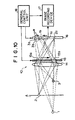
- a parallax image input apparatus 10' which serves as the embodiment of the parallax image input apparatus in accordance with the present invention, comprises the image forming lens 14 for forming the images of the external world, and a microlens array 25 for controlling the input position for images in the image forming lens 14.
- the parallax image input apparatus 10' also comprises an imaging device 26, which images the image information having been acquired with the image forming lens 14 and the microlens array 25 and converts the image information into image signals.
- the imaging device 26 may be constituted of a CCD image sensor, or the like.
- the parallax image input apparatus 10 further comprises the image recording device 17 for recording the image signals, which have been obtained from the imaging device 26, and the general control unit 18 for controlling the operations of the imaging device 26 and the image recording device 17.
- the image forming lens 14 of the parallax image input apparatus 10' corresponds to the image forming means 4 shown in Figure 9.
- the microlens array 25 and the imaging device (such as the CCD image sensor) 26 correspond to the parallax image pickup means 5 shown in Figure 9.
- the image recording device 17 corresponds to the image recording means 7 shown in Figure 9.
- the general control unit 18 corresponds to the general control means 8 shown in Figure 9.
- the focal point of the image forming lens 14 is adjusted such that an in-focus image of the most central object may be formed on the microlens array 25.
- the object 2 is located on an image forming lens focal plane A, which lies on the side leftward from the image forming lens 14, and an in-focus image 2d of the object 2 is obtained on an image forming lens focal plane A', which lies on the side rightward from the image forming lens 14.
- the microlens array 25 is located on the image forming lens focal plane A'.
- the position of the pupil of the image forming lens 14 is set to coincide with a microlens focal plane B, which lies on the side leftward from the microlens array 25, and the imaging device 26 is located on a microlens focal plane B', which lies on the side rightward from the microlens array 25.
- the imaging, device 26 is processed as an array of small regions, each of which corresponds to one of the microlenses of the microlens array 25.
- the number of the thus obtained parallax image coincides with the number of the elements of the microlens array 25 and the number of the small regions of the imaging device 26.
- the operation for acquiring the continuous parallax images is accomplished by the functions of the microlens array 25 for spatial separation of the image of the pupil of the image forming lens 14.
- a point light source 31 is located at the position of the real image 25a' of the microlens 25a, the real image 25a' being formed on the image forming lens focal plane A, will be described hereinbelow.
- the microlens 25a which is the fourth microlens from the bottom, is taken as an example.
- the light having been radiated out of the point light source 31 diverges and impinges upon the pupil plane of the image forming lens 14.
- the direction of the optical path of the light having been radiated out of the point light source 31 is bent by the action of the image forming lens 14, and the light converges toward the microlens 25a.
- the image of the point light source 31 is formed at the position of the fourth microlens 25a from the bottom. Specifically, the light, which has passed through every portion of the image forming lens 14, impinges upon the fourth microlens 25a from the bottom. Therefore, as illustrated in Figure 14A, if the image forming lens 14 is looked from the position of the fourth microlens 25a from the bottom, the light coming from the point light source 31 can be seen as spreading over the entire area of the pupil plane of the image forming lens 14. The light coming from the point light source 31 does not impinge upon the microlenses other than the microlens 25a.
- a light component radiated out of the point light source 31, which light component can impinge upon a microlens 25b, is illustrated with the hatched region.
- the pupil plane is looked from the position of the microlens 25b on the image forming lens focal plane A' shown in Figure 15, an unsharp image 31b of the point light source 31 can be seen at only an upper portion of the pupil plane.
- an unsharp image 31a of the point light source 31 can be seen at an approximately middle portion of the pupil plane.
- the point light source 31 lies on the side outward from a truncated circular cone-shaped region, which shows the range of light capable of impinging upon the microlens 25c. Therefore, of the light having been radiated out of the point light source 31, a light component (in the region hatched in Figure 16), which follows an optical path passing through the image of the microlens 25c, travels to the side outward from the pupil of the image forming lens 14.
- the light component cannot pass through the image forming lens 14.
- the image forming lens 14 is looked from the position of the microlens 25c, the light coming from the point light source 31 is not seen in the pupil plane of the image forming lens 14, and a black image is obtained on the small region of the imaging device 26 corresponding to the microlens 25c.
- the image formed on the imaging device 26 is the image of the pupil plane of the image forming lens 14. Therefore, the optical path of the light capable of impinging upon the position of each picture element of the image formed on the imaging device 26 is determined naturally in accordance with the principle of the geometric optics.
- the light components which are capable of impinging upon a certain picture element 26a located at a lower portion of a certain small region of the imaging device 26, are limited to those which come from radiating points lying in the netted region on the side leftward from the image forming lens 14.
- Amore important feature is that, of the light components capable of impinging upon the picture element 26a, the light component which actually impinges upon the picture element 26a is only the one which travels along the optical path in the netted region.
- a picture element at the middle portion of the image, which is formed on the imaging device 26 by each microlens of the microlens array 25, is the one which is constituted of a light component having passed through the middle portion of the image forming lens 14.
- a picture element at a peripheral portion of the image, which is formed on the imaging device 26 by each microlens of the microlens array 25, is the one which is constituted of a light component having passed through a peripheral portion of the image forming lens 14.
- each of the images formed by the microlens array 25 is the one which is obtained by spatially separating the light signals coming to each microlens, the spatial separation being effected in accordance with the light passage positions in the pupil plane of the image forming lens 14.
- the signals at middle portions of the images formed by the microlenses may be collected, and a single image may be reconstructed from the collected signals.
- an image can be obtained which is composed of only the light signals having passed through the middle portion of the pupil plane of the image forming lens 14.
- only the signals at lower portions of the images formed by the microlenses may be collected, and a single image may be reconstructed from the collected signals.
- an image can be obtained which is composed of only the light signals having passed through the upper portion of the pupil plane of the image forming lens 14. In this manner, only the signals at specific positions in the small images formed by the microlenses can be sampled, and an image can be reconstructed from the sampled signals.
- Figure 19 shows a region of existence of light source points, which constitute signals at lower end portions of images in an image group 14' formed by the microlenses of the microlens array 25.
- the signals at the lower end portions of the images in the image group 14' formed by the microlenses of the microlens array 25 are constituted of only the light having passed through the upper end portion of the pupil plane of the image forming lens 14.
- the viewpoint is set at the upper end portion of the image forming lens 14, and that the light signal components coming along various directions from the external world and passing through the positions of images 25', 25', ...
- the distribution of the signals, which are obtained by arraying the light signal components in order, is equivalent to the distribution of light intensity (i.e., the image) of the external world, which is obtained when the viewpoint is set at the upper end portion of the image forming lens 14.
- the image, which is reconstructed by sampling the signals at the corresponding positions in the images formed on the imaging device 26, is equivalent to the image of the external world, which image is obtained when the viewpoint is set at a position on the image forming lens 14 corresponding to the sampling positions.
- the reconstructed images, which are constituted of the signal components sampled at different sampling positions in the images formed on the imaging device 26, have the parallax with respect to one another.
- the reconstructed images can be obtained such that the parallax may vary little by little among them.
- the continuous parallax images can be obtained in this manner.
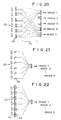
- the signals necessary for constructing the image seen from each viewpoint are spatially independent from one another. Therefore, as illustrated in Figure 20, as the sampling means for each image, a signal distributing means 40 having a plurality of signal lines is empolyed. In such case, a plurality of images can be acquired simultaneously.
- the ability of simultaneously acquiring a plurality of parallax images has the features in that the time required to acquire the images can be kept short and in that, since a sampling time lag does not occur among the parallax images, blur does not occur even for a quickly moving object. Also, since a scanning mechanism need not be used, the constitution of the parallax image input apparatus can be kept simple. However, in the embodiment, the image plane of the image forming lens 14 is divided by the microlens array 25. Therefore, from the view point of the spatial resolution, the example in which the entire image information is acquired on a single parallax image, is more advantageous than the second embodiment.
- sampling method of Figure 20 for each image on the imaging device 26, a plurality of images are acquired simultaneously.
- sampling of only the components having passed through a certain pupil position may be carried out successively, and parallax images may thereby be obtained successively.
- light receiving elements 26, 26, ... may be moved.
- a light shutter 15' may be moved.
- the microlens array and the pinhole array may be a one-dimensional array or may be a two-dimensional array.
- a lens array having lens power in only a one-dimensional direction such as a cylindrical lens array
- a lens array having lens power in two-dimensional directions such as a spherical lens array
Landscapes
- Engineering & Computer Science (AREA)
- Multimedia (AREA)
- Signal Processing (AREA)
- Testing, Inspecting, Measuring Of Stereoscopic Televisions And Televisions (AREA)
- Measurement Of Optical Distance (AREA)
Claims (8)
- Parallaxenbild-Eingabevorrichtung zum Erfassen mehrerer, aus unterschiedlichen Blickwinkeln gesehenen Bildern, umfassend:wobei die Parallaxenbild-Aufnahmeeinrichtung (5; 25, 26) aufweist:i) eine Bilderzeugungseinrichtung (4; 14) zum Erzeugen von Bildern der Außenwelt,ii) eine Parallexenbild-Aufnahmeeinrichtung (5; 25, 26) zum selektiven Abbilden von Stücken von Bildinformation, die durch verschiedene Stellen in der Bilderzeugungseinrichtung gegangen sind, und Umwandeln der Bildinformationsstücke in Bildsignale, undiii) eine Bildaufzeichnungseinrichtung (7; 17) zum Aufzeichnen der Bildsignale, die von der Parallaxenbild-Aufnahmeeinrichtung (5; 25, 26) erhalten wurden,wobei jede der kleinen Zonen der Abbildungseinrichtung (26) eine Mehrzahl von Bildelementbereichen aufweist und die Bildinformation, deren Bild erzeugt wurde, in ein Bildsignal umwandelt, wobei eine Signalverteilungseinrichtung (40) mit mehreren Signalleitungen an die Abbildungseinrichtung angeschlossen ist, um gleichzeitig mehrere Parallaxenbilder zu erfassen.a) eine Bilderzeugungselementengruppe (25), zusammengesetzt aus mehreren Bilderzeugungselementen, die jeweils auf einer zweiten Bildebene (B') ein Bild eines von verschiedenen Teilen eines Bilds erzeugen, das von der Bilderzeugungseinrichtung (4; 14) auf einer ersten Bildebene (A) erzeugt wurde, undb) eine Abbildungseinrichtung (26), die eine Mehrzahl kleiner Zonen aufweist, die sich auf der zweiten Bildebene (B') befinden, um den mehreren Bilderzeugungselementen zu entsprechen,
- Vorrichtung nach Anspruch 1, bei der die Abbildungseinrichtung (26) mehrere Abbildungselemente aufweist, von denen jedes eine Abbildungsebene besitzt, die einer der kleinen Zonen entspricht.
- Vorrichtung nach Anspruch 1, bei der die Bilderzeugungselementengruppe (25) ein Linsenfeld aufweist, das Brechkraft in zweidimensionale Richtungen besitzt.
- Vorrichtung nach Anspruch 1, bei dem die Bilderzeugungselementengruppe (25) ein Zylinderlinsenfeld ist, das Brechkraft in nur einer eindimensionalen Richtung besitzt.
- Vorrichtung nach Anspruch 1, bei der die Abbildungseinrichtung (26) gleichzeitig mehrere Bildinformationsstücke abbildet, die durch verschiedene Stellen in der Bilderzeugungseinrichtung (4; 14) gegangen sind.
- Vorrichtung nach Anspruch 1, bei der die Abbildungseinrichtung (26) eine photoelektrische bildgebende Wandlereinrichtung ist.
- Vorrichtung nach Anspruch 1, bei der die Abbildungseinrichtung (26) eine auf photochemischer Reaktion beruhende Abbildungseinrichtung ist.
- Vorrichtung nach Anspruch 1, bei der mehrere Parallaxenbilder dadurch erhalten werden, daß Bildsignale rekonstruiert werden, welche von der Abbildungseinrichtung (26) erhalten wurden.
Applications Claiming Priority (3)
| Application Number | Priority Date | Filing Date | Title |
|---|---|---|---|
| JP19185396A JP3753201B2 (ja) | 1996-07-22 | 1996-07-22 | 視差画像入力装置 |
| JP19185396 | 1996-07-22 | ||
| JP191853/96 | 1996-07-22 |
Publications (2)
| Publication Number | Publication Date |
|---|---|
| EP0821532A1 EP0821532A1 (de) | 1998-01-28 |
| EP0821532B1 true EP0821532B1 (de) | 2002-12-11 |
Family
ID=16281604
Family Applications (1)
| Application Number | Title | Priority Date | Filing Date |
|---|---|---|---|
| EP19970112471 Expired - Lifetime EP0821532B1 (de) | 1996-07-22 | 1997-07-21 | Kamera für dreidimensionale Bildaufnahme |
Country Status (4)
| Country | Link |
|---|---|
| US (1) | US6233003B1 (de) |
| EP (1) | EP0821532B1 (de) |
| JP (1) | JP3753201B2 (de) |
| DE (1) | DE69717733T2 (de) |
Families Citing this family (45)
| Publication number | Priority date | Publication date | Assignee | Title |
|---|---|---|---|---|
| US6535249B1 (en) * | 1998-11-03 | 2003-03-18 | Hewlett-Packard Development Company, L.P. | Digital camera optical system with field lens |
| US6850210B1 (en) * | 1998-11-12 | 2005-02-01 | Stereographics Corporation | Parallax panoramagram having improved depth and sharpness |
| US6396873B1 (en) * | 1999-02-25 | 2002-05-28 | Envision Advanced Medical Systems | Optical device |
| EP1083755A3 (de) * | 1999-09-07 | 2003-11-12 | Canon Kabushiki Kaisha | Bildeingabegerät und Bildanzeigevorrichtung |
| JP4534337B2 (ja) * | 2000-10-19 | 2010-09-01 | ソニー株式会社 | 撮影装置及び撮影方法、並びに、画像生成装置及び画像生成方法 |
| US7001019B2 (en) * | 2000-10-26 | 2006-02-21 | Canon Kabushiki Kaisha | Image observation apparatus and system |
| JP2002344999A (ja) | 2001-05-21 | 2002-11-29 | Asahi Optical Co Ltd | ステレオ画像撮像装置 |
| US7265775B2 (en) * | 2002-03-28 | 2007-09-04 | Kabushiki Kaisha Toshiba | Three-dimensional display apparatus |
| GB0322681D0 (en) | 2003-09-27 | 2003-10-29 | Koninkl Philips Electronics Nv | Multi-view display |
| US7671916B2 (en) * | 2004-06-04 | 2010-03-02 | Electronic Arts Inc. | Motion sensor using dual camera inputs |
| WO2006039486A2 (en) * | 2004-10-01 | 2006-04-13 | The Board Of Trustees Of The Leland Stanford Junior University | Imaging arrangements and methods therefor |
| US8358354B2 (en) | 2009-01-26 | 2013-01-22 | The Board Of Trustees Of The Leland Stanford Junior University | Correction of optical abberations |
| FR2924235B1 (fr) * | 2007-11-27 | 2010-08-20 | Commissariat Energie Atomique | Dispositif d'imagerie visible a filtre colore |
| KR101419979B1 (ko) | 2008-01-29 | 2014-07-16 | 톰슨 라이센싱 | 2d 이미지 데이터를 스테레오스코픽 이미지 데이터로 변환하기 위한 방법 및 시스템 |
| JP2009290268A (ja) * | 2008-05-27 | 2009-12-10 | Sony Corp | 撮像装置 |
| JP5229541B2 (ja) * | 2008-05-29 | 2013-07-03 | 株式会社ニコン | 距離測定装置、距離測定方法、及び、プログラム |
| US8242427B2 (en) * | 2008-08-12 | 2012-08-14 | Digital Fusion, Inc. | System and method for optically co-registering pixels |
| JP5301414B2 (ja) * | 2009-10-28 | 2013-09-25 | 京セラ株式会社 | 撮像装置 |
| JP2011182041A (ja) * | 2010-02-26 | 2011-09-15 | Nippon Hoso Kyokai <Nhk> | 撮像装置 |
| CN102884802B (zh) | 2010-03-24 | 2014-03-12 | 富士胶片株式会社 | 三维成像装置和视点图像恢复方法 |
| KR101692397B1 (ko) * | 2010-05-28 | 2017-01-03 | 삼성전자주식회사 | 광량 조절장치, 촬영장치 및 촬영방법 |
| JP5269252B2 (ja) * | 2010-06-29 | 2013-08-21 | 富士フイルム株式会社 | 単眼立体撮像装置 |
| TW201200959A (en) | 2010-06-29 | 2012-01-01 | Fujifilm Corp | One-eyed stereo photographic device |
| CN103039066B (zh) * | 2010-06-30 | 2016-01-27 | 富士胶片株式会社 | 成像装置、图像处理装置以及图像处理方法 |
| WO2012002298A1 (ja) | 2010-06-30 | 2012-01-05 | 富士フイルム株式会社 | 撮像装置および撮像方法 |
| JP5628913B2 (ja) * | 2010-06-30 | 2014-11-19 | 富士フイルム株式会社 | 撮像装置および撮像方法 |
| WO2012043211A1 (ja) | 2010-10-01 | 2012-04-05 | 富士フイルム株式会社 | 撮像装置 |
| EP2624541B1 (de) | 2010-10-01 | 2016-11-30 | FUJIFILM Corporation | Bildgebungsvorrichtung |
| JP2012113281A (ja) | 2010-11-04 | 2012-06-14 | Panasonic Corp | 立体撮像光学系、撮像装置及びカメラ |
| WO2012108099A1 (ja) * | 2011-02-09 | 2012-08-16 | 富士フイルム株式会社 | 撮像装置および撮像方法 |
| JP5433109B2 (ja) | 2011-03-31 | 2014-03-05 | 富士フイルム株式会社 | 立体撮像装置および立体撮像方法 |
| JP5825817B2 (ja) * | 2011-04-01 | 2015-12-02 | キヤノン株式会社 | 固体撮像素子及び撮像装置 |
| WO2013027513A1 (ja) | 2011-08-19 | 2013-02-28 | 富士フイルム株式会社 | 撮像装置及びシェーディング補正方法 |
| EP3267677B1 (de) * | 2011-08-24 | 2019-08-28 | Fujifilm Corporation | Bildgebungsvorrichtung |
| JP5611469B2 (ja) * | 2011-09-09 | 2014-10-22 | 富士フイルム株式会社 | 立体撮像装置および方法 |
| JP5857782B2 (ja) * | 2012-02-15 | 2016-02-10 | 株式会社ニコン | 撮像装置 |
| JP6042096B2 (ja) * | 2012-05-09 | 2016-12-14 | 東芝メディカルシステムズ株式会社 | X線撮影装置及び医用画像処理装置 |
| JP6253380B2 (ja) * | 2013-12-11 | 2017-12-27 | キヤノン株式会社 | 画像処理方法、画像処理装置および撮像装置 |
| KR102198852B1 (ko) * | 2014-03-24 | 2021-01-05 | 삼성전자 주식회사 | 홍채 인식 장치 및 이를 포함하는 모바일 장치 |
| JP6363857B2 (ja) * | 2014-03-24 | 2018-07-25 | キヤノン株式会社 | 撮像素子、撮像装置、画像処理方法、並びにプログラム |
| JP6294757B2 (ja) * | 2014-05-12 | 2018-03-14 | 日本電信電話株式会社 | 位置関係検出装置及び位置関係検出方法 |
| US11453513B2 (en) * | 2018-04-26 | 2022-09-27 | Skydio, Inc. | Autonomous aerial vehicle hardware configuration |
| JP7145048B2 (ja) * | 2018-11-16 | 2022-09-30 | キヤノン株式会社 | 撮像装置及びその制御方法、プログラム、記憶媒体 |
| MX2024004577A (es) * | 2021-10-15 | 2024-07-10 | Real Time Robotics Inc | Un multicoptero. |
| US12030399B2 (en) | 2022-04-27 | 2024-07-09 | Skydio, Inc. | Base stations for unmanned aerial vehicles (UAVs) |
Family Cites Families (10)
| Publication number | Priority date | Publication date | Assignee | Title |
|---|---|---|---|---|
| US3677317A (en) * | 1970-11-12 | 1972-07-18 | Enger Kress Co | Ladies clutch bag with coin purse |
| US4677468A (en) * | 1984-08-13 | 1987-06-30 | Nec Home Electronics Ltd. | Stereoscopic television image-pickup device display device |
| SE461619B (sv) * | 1988-07-06 | 1990-03-05 | Hasselblad Ab Victor | Anordning vid kameror utgoerande en sammansaettning av en fotokemisk och en elektronisk kamera |
| JPH06500445A (ja) * | 1991-06-12 | 1994-01-13 | リー、スン | 3次元イメージの記録および再生 |
| ES2165644T3 (es) * | 1993-05-05 | 2002-03-16 | Pierre Allio | Dispositivo de video autoestereoscopico. |
| US5475513A (en) * | 1993-06-02 | 1995-12-12 | Sharp Kabushiki Kaisha | Projection type image display device maintaining resolution of an image unaffected by parallax |
| GB2282505A (en) * | 1993-09-23 | 1995-04-05 | Sharp Kk | Three dimensional imaging apparatus |
| US5448322A (en) * | 1993-11-05 | 1995-09-05 | Vision Iii Imaging, Inc. | Autostereoscopic imaging apparatus and method using a parallax scanning lens aperture |
| JPH0822091A (ja) * | 1994-07-05 | 1996-01-23 | Canon Inc | 立体画像記録方法および装置ならびに立体画像形成体 |
| US5717453A (en) * | 1995-06-07 | 1998-02-10 | Meso Scale Technology, Inc. | Three dimensional imaging system |
-
1996
- 1996-07-22 JP JP19185396A patent/JP3753201B2/ja not_active Expired - Lifetime
-
1997
- 1997-07-21 DE DE69717733T patent/DE69717733T2/de not_active Expired - Lifetime
- 1997-07-21 EP EP19970112471 patent/EP0821532B1/de not_active Expired - Lifetime
- 1997-07-22 US US08/898,659 patent/US6233003B1/en not_active Expired - Lifetime
Also Published As
| Publication number | Publication date |
|---|---|
| DE69717733D1 (de) | 2003-01-23 |
| EP0821532A1 (de) | 1998-01-28 |
| DE69717733T2 (de) | 2003-05-28 |
| JP3753201B2 (ja) | 2006-03-08 |
| US6233003B1 (en) | 2001-05-15 |
| JPH1042314A (ja) | 1998-02-13 |
Similar Documents
| Publication | Publication Date | Title |
|---|---|---|
| EP0821532B1 (de) | Kamera für dreidimensionale Bildaufnahme | |
| Okano et al. | Real-time integral imaging based on extremely high resolution video system | |
| CN103472592B (zh) | 一种快照式高通量的偏振成像方法和偏振成像仪 | |
| US20130188024A1 (en) | Apparatus method and system for imaging | |
| US10021340B2 (en) | Method and an apparatus for generating data representative of a light field | |
| US20020140835A1 (en) | Single sensor chip digital stereo camera | |
| Hwang et al. | Free view 3-D visualization of occluded objects by using computational synthetic aperture integral imaging | |
| TW201012202A (en) | Solid-state panoramic image capture apparatus | |
| CN108093237A (zh) | 高空间分辨率光场采集装置与图像生成方法 | |
| EP1057009A2 (de) | Kamera mit einer kodierten blende zur dreidimensionalen abbildung | |
| EP3664433A1 (de) | Informationsverarbeitungsvorrichtung, informationsverarbeitungsverfahren und programm und austauschbare linse | |
| JPH0792519A (ja) | 光画像プロセッサ、光画像処理システム及び光画像相関器 | |
| US6233035B1 (en) | Image recording apparatus and image reproducing apparatus | |
| Gurrieri et al. | Acquisition of omnidirectional stereoscopic images and videos of dynamic scenes: a review | |
| Piao et al. | Extended depth of field integral imaging using multi-focus fusion | |
| KR100915039B1 (ko) | 다중 초점 2차원 영상을 이용한 3차원 입체 영상 변환 방법및 변환 장치와 이를 위한 기록매체 | |
| JP2019133214A (ja) | 画像表示装置、該装置を含む映像表示システム、画像表示方法および画像表示用プログラム | |
| EP3143583B1 (de) | Systeme und verfahren zur verbesserten computergestützten bildgebung | |
| Favaro | A split-sensor light field camera for extended depth of field and superresolution | |
| KR101025785B1 (ko) | 3차원 실물 화상장치 | |
| EP3482562B1 (de) | Vorrichtung und verfahren zur erzeugung von daten, die einen pixelstrahl repräsentieren | |
| JP3564383B2 (ja) | 3次元動画入力装置 | |
| Ducrocq et al. | A Survey on Adaptive Cameras | |
| JPH118863A (ja) | 3次元カメラ | |
| KR20010084470A (ko) | 가상 스튜디오에서의 카메라 움직임 추출 장치 및 방법 |
Legal Events
| Date | Code | Title | Description |
|---|---|---|---|
| PUAI | Public reference made under article 153(3) epc to a published international application that has entered the european phase |
Free format text: ORIGINAL CODE: 0009012 |
|
| AK | Designated contracting states |
Kind code of ref document: A1 Designated state(s): AT BE CH DE DK ES FI FR GB GR IE IT LI LU MC NL PT SE |
|
| 17P | Request for examination filed |
Effective date: 19980617 |
|
| RBV | Designated contracting states (corrected) |
Designated state(s): DE FR GB |
|
| 17Q | First examination report despatched |
Effective date: 20001017 |
|
| GRAG | Despatch of communication of intention to grant |
Free format text: ORIGINAL CODE: EPIDOS AGRA |
|
| GRAG | Despatch of communication of intention to grant |
Free format text: ORIGINAL CODE: EPIDOS AGRA |
|
| GRAH | Despatch of communication of intention to grant a patent |
Free format text: ORIGINAL CODE: EPIDOS IGRA |
|
| GRAH | Despatch of communication of intention to grant a patent |
Free format text: ORIGINAL CODE: EPIDOS IGRA |
|
| GRAA | (expected) grant |
Free format text: ORIGINAL CODE: 0009210 |
|
| AK | Designated contracting states |
Kind code of ref document: B1 Designated state(s): DE FR GB |
|
| REG | Reference to a national code |
Ref country code: GB Ref legal event code: FG4D |
|
| REF | Corresponds to: |
Ref document number: 69717733 Country of ref document: DE Date of ref document: 20030123 |
|
| ET | Fr: translation filed | ||
| PLBE | No opposition filed within time limit |
Free format text: ORIGINAL CODE: 0009261 |
|
| STAA | Information on the status of an ep patent application or granted ep patent |
Free format text: STATUS: NO OPPOSITION FILED WITHIN TIME LIMIT |
|
| 26N | No opposition filed |
Effective date: 20030912 |
|
| REG | Reference to a national code |
Ref country code: GB Ref legal event code: 732E |
|
| REG | Reference to a national code |
Ref country code: FR Ref legal event code: TP Ref country code: FR Ref legal event code: CD |
|
| REG | Reference to a national code |
Ref country code: FR Ref legal event code: PLFP Year of fee payment: 20 |
|
| PGFP | Annual fee paid to national office [announced via postgrant information from national office to epo] |
Ref country code: FR Payment date: 20160613 Year of fee payment: 20 |
|
| PGFP | Annual fee paid to national office [announced via postgrant information from national office to epo] |
Ref country code: GB Payment date: 20160720 Year of fee payment: 20 Ref country code: DE Payment date: 20160712 Year of fee payment: 20 |
|
| REG | Reference to a national code |
Ref country code: DE Ref legal event code: R071 Ref document number: 69717733 Country of ref document: DE |
|
| REG | Reference to a national code |
Ref country code: GB Ref legal event code: PE20 Expiry date: 20170720 |
|
| PG25 | Lapsed in a contracting state [announced via postgrant information from national office to epo] |
Ref country code: GB Free format text: LAPSE BECAUSE OF EXPIRATION OF PROTECTION Effective date: 20170720 |