EP0821758B1 - Charnieres extrudees et portes repliables realisees avec des charnieres - Google Patents
Charnieres extrudees et portes repliables realisees avec des charnieres Download PDFInfo
- Publication number
- EP0821758B1 EP0821758B1 EP96908961A EP96908961A EP0821758B1 EP 0821758 B1 EP0821758 B1 EP 0821758B1 EP 96908961 A EP96908961 A EP 96908961A EP 96908961 A EP96908961 A EP 96908961A EP 0821758 B1 EP0821758 B1 EP 0821758B1
- Authority
- EP
- European Patent Office
- Prior art keywords
- part circular
- hinge
- wall
- segment
- segments
- Prior art date
- Legal status (The legal status is an assumption and is not a legal conclusion. Google has not performed a legal analysis and makes no representation as to the accuracy of the status listed.)
- Expired - Lifetime
Links
- 230000015572 biosynthetic process Effects 0.000 claims abstract description 21
- 238000005755 formation reaction Methods 0.000 claims description 18
- 239000000463 material Substances 0.000 claims description 7
- 239000004033 plastic Substances 0.000 claims description 6
- 229920003023 plastic Polymers 0.000 claims description 6
- 239000012815 thermoplastic material Substances 0.000 claims description 4
- 241000237519 Bivalvia Species 0.000 claims 1
- 239000004698 Polyethylene Substances 0.000 claims 1
- 235000020639 clam Nutrition 0.000 claims 1
- -1 polyethylene Polymers 0.000 claims 1
- 229920000573 polyethylene Polymers 0.000 claims 1
- 238000001125 extrusion Methods 0.000 abstract description 3
- 230000007246 mechanism Effects 0.000 description 5
- 238000004519 manufacturing process Methods 0.000 description 3
- 229910052751 metal Inorganic materials 0.000 description 3
- 239000002184 metal Substances 0.000 description 3
- VTYYLEPIZMXCLO-UHFFFAOYSA-L Calcium carbonate Chemical compound [Ca+2].[O-]C([O-])=O VTYYLEPIZMXCLO-UHFFFAOYSA-L 0.000 description 2
- 238000009434 installation Methods 0.000 description 2
- 238000012423 maintenance Methods 0.000 description 2
- 239000002023 wood Substances 0.000 description 2
- 241001449342 Chlorocrambe hastata Species 0.000 description 1
- 229910000019 calcium carbonate Inorganic materials 0.000 description 1
- 239000003795 chemical substances by application Substances 0.000 description 1
- 230000000694 effects Effects 0.000 description 1
- 239000003000 extruded plastic Substances 0.000 description 1
- 239000000945 filler Substances 0.000 description 1
- 229920001903 high density polyethylene Polymers 0.000 description 1
- 239000004700 high-density polyethylene Substances 0.000 description 1
- 230000013011 mating Effects 0.000 description 1
- 239000000203 mixture Substances 0.000 description 1
- 238000010422 painting Methods 0.000 description 1
- 239000003223 protective agent Substances 0.000 description 1
- 239000003351 stiffener Substances 0.000 description 1
- 230000001360 synchronised effect Effects 0.000 description 1
- 125000000391 vinyl group Chemical group [H]C([*])=C([H])[H] 0.000 description 1
- 229920002554 vinyl polymer Polymers 0.000 description 1
Images
Classifications
-
- E—FIXED CONSTRUCTIONS
- E06—DOORS, WINDOWS, SHUTTERS, OR ROLLER BLINDS IN GENERAL; LADDERS
- E06B—FIXED OR MOVABLE CLOSURES FOR OPENINGS IN BUILDINGS, VEHICLES, FENCES OR LIKE ENCLOSURES IN GENERAL, e.g. DOORS, WINDOWS, BLINDS, GATES
- E06B3/00—Window sashes, door leaves, or like elements for closing wall or like openings; Layout of fixed or moving closures, e.g. windows in wall or like openings; Features of rigidly-mounted outer frames relating to the mounting of wing frames
- E06B3/32—Arrangements of wings characterised by the manner of movement; Arrangements of movable wings in openings; Features of wings or frames relating solely to the manner of movement of the wing
- E06B3/48—Wings connected at their edges, e.g. foldable wings
- E06B3/485—Sectional doors
- E06B3/486—Sectional doors with hinges being at least partially integral part of the section panels
-
- E—FIXED CONSTRUCTIONS
- E05—LOCKS; KEYS; WINDOW OR DOOR FITTINGS; SAFES
- E05D—HINGES OR SUSPENSION DEVICES FOR DOORS, WINDOWS OR WINGS
- E05D15/00—Suspension arrangements for wings
- E05D15/16—Suspension arrangements for wings for wings sliding vertically more or less in their own plane
- E05D15/24—Suspension arrangements for wings for wings sliding vertically more or less in their own plane consisting of parts connected at their edges
- E05D15/242—Hinge connections between the parts
-
- E—FIXED CONSTRUCTIONS
- E05—LOCKS; KEYS; WINDOW OR DOOR FITTINGS; SAFES
- E05F—DEVICES FOR MOVING WINGS INTO OPEN OR CLOSED POSITION; CHECKS FOR WINGS; WING FITTINGS NOT OTHERWISE PROVIDED FOR, CONCERNED WITH THE FUNCTIONING OF THE WING
- E05F15/00—Power-operated mechanisms for wings
- E05F15/60—Power-operated mechanisms for wings using electrical actuators
- E05F15/603—Power-operated mechanisms for wings using electrical actuators using rotary electromotors
- E05F15/665—Power-operated mechanisms for wings using electrical actuators using rotary electromotors for vertically-sliding wings
- E05F15/668—Power-operated mechanisms for wings using electrical actuators using rotary electromotors for vertically-sliding wings for overhead wings
- E05F15/67—Power-operated mechanisms for wings using electrical actuators using rotary electromotors for vertically-sliding wings for overhead wings operated by flexible or rigid rack-and-pinion arrangements
-
- E—FIXED CONSTRUCTIONS
- E06—DOORS, WINDOWS, SHUTTERS, OR ROLLER BLINDS IN GENERAL; LADDERS
- E06B—FIXED OR MOVABLE CLOSURES FOR OPENINGS IN BUILDINGS, VEHICLES, FENCES OR LIKE ENCLOSURES IN GENERAL, e.g. DOORS, WINDOWS, BLINDS, GATES
- E06B3/00—Window sashes, door leaves, or like elements for closing wall or like openings; Layout of fixed or moving closures, e.g. windows in wall or like openings; Features of rigidly-mounted outer frames relating to the mounting of wing frames
- E06B3/32—Arrangements of wings characterised by the manner of movement; Arrangements of movable wings in openings; Features of wings or frames relating solely to the manner of movement of the wing
- E06B3/48—Wings connected at their edges, e.g. foldable wings
- E06B3/485—Sectional doors
-
- E—FIXED CONSTRUCTIONS
- E05—LOCKS; KEYS; WINDOW OR DOOR FITTINGS; SAFES
- E05D—HINGES OR SUSPENSION DEVICES FOR DOORS, WINDOWS OR WINGS
- E05D1/00—Pinless hinges; Substitutes for hinges
- E05D1/04—Pinless hinges; Substitutes for hinges with guide members shaped as circular arcs
-
- E—FIXED CONSTRUCTIONS
- E05—LOCKS; KEYS; WINDOW OR DOOR FITTINGS; SAFES
- E05D—HINGES OR SUSPENSION DEVICES FOR DOORS, WINDOWS OR WINGS
- E05D15/00—Suspension arrangements for wings
- E05D15/16—Suspension arrangements for wings for wings sliding vertically more or less in their own plane
- E05D15/24—Suspension arrangements for wings for wings sliding vertically more or less in their own plane consisting of parts connected at their edges
-
- E—FIXED CONSTRUCTIONS
- E05—LOCKS; KEYS; WINDOW OR DOOR FITTINGS; SAFES
- E05Y—INDEXING SCHEME ASSOCIATED WITH SUBCLASSES E05D AND E05F, RELATING TO CONSTRUCTION ELEMENTS, ELECTRIC CONTROL, POWER SUPPLY, POWER SIGNAL OR TRANSMISSION, USER INTERFACES, MOUNTING OR COUPLING, DETAILS, ACCESSORIES, AUXILIARY OPERATIONS NOT OTHERWISE PROVIDED FOR, APPLICATION THEREOF
- E05Y2900/00—Application of doors, windows, wings or fittings thereof
- E05Y2900/10—Application of doors, windows, wings or fittings thereof for buildings or parts thereof
- E05Y2900/106—Application of doors, windows, wings or fittings thereof for buildings or parts thereof for garages
-
- E—FIXED CONSTRUCTIONS
- E06—DOORS, WINDOWS, SHUTTERS, OR ROLLER BLINDS IN GENERAL; LADDERS
- E06B—FIXED OR MOVABLE CLOSURES FOR OPENINGS IN BUILDINGS, VEHICLES, FENCES OR LIKE ENCLOSURES IN GENERAL, e.g. DOORS, WINDOWS, BLINDS, GATES
- E06B9/00—Screening or protective devices for wall or similar openings, with or without operating or securing mechanisms; Closures of similar construction
- E06B9/02—Shutters, movable grilles, or other safety closing devices, e.g. against burglary
- E06B9/08—Roll-type closures
- E06B9/11—Roller shutters
- E06B9/15—Roller shutters with closing members formed of slats or the like
- E06B2009/1505—Slat details
- E06B2009/1527—Transparent slats or transparent sections in slats
-
- E—FIXED CONSTRUCTIONS
- E06—DOORS, WINDOWS, SHUTTERS, OR ROLLER BLINDS IN GENERAL; LADDERS
- E06B—FIXED OR MOVABLE CLOSURES FOR OPENINGS IN BUILDINGS, VEHICLES, FENCES OR LIKE ENCLOSURES IN GENERAL, e.g. DOORS, WINDOWS, BLINDS, GATES
- E06B9/00—Screening or protective devices for wall or similar openings, with or without operating or securing mechanisms; Closures of similar construction
- E06B9/02—Shutters, movable grilles, or other safety closing devices, e.g. against burglary
- E06B9/08—Roll-type closures
- E06B9/11—Roller shutters
- E06B9/15—Roller shutters with closing members formed of slats or the like
- E06B2009/1533—Slat connections
- E06B2009/1538—Slats directly connected
- E06B2009/1544—Engaging section has curved articulation surfaces
-
- E—FIXED CONSTRUCTIONS
- E06—DOORS, WINDOWS, SHUTTERS, OR ROLLER BLINDS IN GENERAL; LADDERS
- E06B—FIXED OR MOVABLE CLOSURES FOR OPENINGS IN BUILDINGS, VEHICLES, FENCES OR LIKE ENCLOSURES IN GENERAL, e.g. DOORS, WINDOWS, BLINDS, GATES
- E06B9/00—Screening or protective devices for wall or similar openings, with or without operating or securing mechanisms; Closures of similar construction
- E06B9/02—Shutters, movable grilles, or other safety closing devices, e.g. against burglary
- E06B9/08—Roll-type closures
- E06B9/11—Roller shutters
- E06B9/15—Roller shutters with closing members formed of slats or the like
- E06B2009/1533—Slat connections
- E06B2009/155—Slats connected by separate elements
- E06B2009/1566—Rigid elements, e.g. hinges, hooks or profiles
-
- E—FIXED CONSTRUCTIONS
- E06—DOORS, WINDOWS, SHUTTERS, OR ROLLER BLINDS IN GENERAL; LADDERS
- E06B—FIXED OR MOVABLE CLOSURES FOR OPENINGS IN BUILDINGS, VEHICLES, FENCES OR LIKE ENCLOSURES IN GENERAL, e.g. DOORS, WINDOWS, BLINDS, GATES
- E06B9/00—Screening or protective devices for wall or similar openings, with or without operating or securing mechanisms; Closures of similar construction
- E06B9/02—Shutters, movable grilles, or other safety closing devices, e.g. against burglary
- E06B9/08—Roll-type closures
- E06B9/11—Roller shutters
- E06B9/17—Parts or details of roller shutters, e.g. suspension devices, shutter boxes, wicket doors, ventilation openings
- E06B2009/17092—Manufacturing
Definitions
- This invention relates to a novel hinge arrangement particularly adapted for hingedly connecting large panels such as used in overhead folding garage doors and to such doors using the novel hinge arrangement.
- garage doors are usually formed of rows of wood panels hinged together by a number of separate metal hinges fastened thereto.
- the doors also have a series of separately mounted rollers at their edges which run in tracks extending upwardly at the sides of the door opening and horizontally inwardly at the top of the door opening so that the door can be moved upwardly and then because of the hinging arrangement move horizontally inwardly at the top of the door opening.
- Very frequently such folding garage doors are provided with a remote controlled motor to raise and lower the doors in response to a signal from a small transmitter device.
- garage doors are both expensive to manufacture both from the cost of the wood and the substantial amount of hardware required in the form of hinges and rollers which have to be individually assembled. Moreover, these doors are heavy and awkward to handle, ship and install.
- the garage door opener mechanisms to handle such heavy doors require motors of significant torque and relatively heavy duties cables, pulleys or other harness for effecting the door movement.
- hinge connection as aforesaid in which the hinge axis is arranged to lie on a line forming the median line between front and rear walls or faces of the hinge members.
- the present invention also provides for the provision of a folding door such as an overhead garage door formed essentially or entirely of plastic material which is significantly less expensive to manufacture and significantly lighter than present such doors and does not require any hinge hardware to assemble nor track hardware to run in the tracks at the sides of the door opening.
- a folding door such as an overhead garage door formed essentially or entirely of plastic material which is significantly less expensive to manufacture and significantly lighter than present such doors and does not require any hinge hardware to assemble nor track hardware to run in the tracks at the sides of the door opening.
- the invention also provides that the hinge members and doors employing same are adapted to be easily assembled so that they can be shipped in knocked down form and assembled at the point of installation.
- the hinges and panels By forming the hinges and panels of plastic material, the components require no maintenance and the arrangement is such that if the door panel becomes damaged it may be simply and easily replaced without having to remove the door from its installed position or disturb the other panels.
- the invention includes a hinge member for use in forming a hinge connection according to the appended claim 1.
- the arrangement is such that the part circular arm segment of the first hinge member is adapted to rotate on the part circular wall segment of the second hinge member and vice versa, and the part circular arm segments are adapted to form a hinge barrel formation for receiving a hinge pintle for rotational movement thereabout centered on said common center.
- the hinge members are also provided with means whereby a connection can be effected to panel members to be hinged.
- the extruded hinge members have parallel front and rear walls and the common center of the part circular segments of the C-shaped formations lie on the median between the front and rear walls.
- the invention also includes a pair of extruded hinge members adapted for part rotational interengagement for use in forming a hinge connection according to the appended claim 6.
- the invention further includes a folding garage door or the like according to the appended claim 10.
- the edges of the panels at the edges of the doors are releasable secured to an edge rail or frame member having an outwardly extending spine notched to provide cog teeth adapted to run in a trackway at the edge of the door with the cog teeth being adapted for engagement with the drive of a garage door opener mechanisms.
- novel hinges of the present invention have wide application but because of their simplicity, strength and free hinging action have particular importance in large hinging structures such as large folding doors, i.e. large overhead garage doors or the like and will be described with reference thereto.
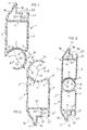
- the hinge member designated at I which is to form the top hinge member in a folding overhead garage door or the like comprises a longitudinal extrusion in the form of a hollow bar having a front wall 2 and a rear wall 3 secured in spaced parallel relation.
- the lower longitudinal edge of the hinge member or bar 1 is formed to present a generally C-shaped socket formation designated at 4.
- This socket formation 4 has a first part circular edge wall segment 5 extending arcuately inwardly of the edge of the front wall 2 to adjacent the rear wall 3 to which it is joined by a short web 6 forming an obtuse angle 7 with the rear wall.
- This wall segment 5 thus forms an arcuate reentrant wall extending the major portion of the distance of the width of the hinge member 1.
- the C-shaped socket formation 4 has a second part circular segment in the form of a curved arm 8 forming part of a circle connected to the inner end of the wall segment 5 by an inward extension of the web 6 forming a shoulder 9 at the juncture of the inner end of the wall segment 5 and the commencement of the part circular arm 8.
- the part circular wall segment 5 and part circular arm 8 have a common center indicated at 10 lying on a line forming the median between the front and rear walls 2 and 3.
- the wall and arm segments 5 and 8 have different radii with the radius 11 of the concave inside surface 12 of the part circular wall segment 5 being just slightly greater than the radius 13 of the outside convex surface 14 of the part circular arm segment 8.
- the front and rear walls 2 and 3 are connected adjacent the upper edge of the hinge member 1 by a transverse web 15 and sloping upwardly and inwardly from the front wall 2 is a wall 16 forming a generally triangular peak 17 with a downwardly extending return wall 18 parallel to the front and rear walls 2 and 3 and offset towards the front wall from the median between the front and rear walls.
- the return wall 18 terminates in a shoulder 19 centered on the median of the front and rear walls and connected to the web 15 by a wall 20 which with the upper portion 21 of the rear wall 3 forms a channel 22 which is necked in at its mouth to provide a slightly restricted entrance 23.
- the hinge member or bar 1 is adapted to interengage with a mating hinge bar or member 1' which in an overhead folding door installation is to form the bottom member of the hinge.
- the hinge member 1' as in the case of the hinge member 1 comprises a longitudinal extrusion in the form of a hollow bar having parallel front and rear walls 2' and 3' respectively and having a C-shaped socket formation designated at 4' which in the case of the hinge bar 1' is formed at the top edge of the member.
- the C-shaped socket formation 4' has a first part circular edge wall segment 5' extending arcuately inwardly of the edge of the front wall 2' to adjacent the rear wall 3' being joined thereto by a web 6' forming an obtuse angle 7' with rear wall 3'.
- the second segment of the C-shaped formation 4' of the hinge member 1' again comprises a part circular arm 8' which in this case is connected to the forward end of the wall segment 5' by a shoulder 9'.
- the part circular wall segment 5' and part circular arm 8' have a common center designated at 10' which again is located on the median of the front and rear walls 2' and 3'.
- the part circular wall segment 5' and the part circular arm 8' have different radii with the radius 11' of the inner concave surface 12' of the wall segment 5' being slightly greater than the radius 13' of the outside convex surface 14' of the part circular arm segment 8'.
- the radius 11' of the concave surface 12' of the wall segment 5' of the hinge member 1' is the same as the radius 11 of the concave surface 12 of the wall segment 5 of the hinge member 1.
- the radius 13' of the outside convex surface 14' of the arm segment 8' of the hinge member 1' is the same as the radius 13 of the outside convex surface 14 of the arm segment 8 of the hinge member 1 with the length of the part circular arm segment 8 of the hinge member being slightly greater than the length of the part circular arm segment 8' of the hinge member 1'.
- the hinge member 1' has the same formation at its lower edge as the hinge member 1 has at its upper edge with the walls 2' and 3' being connected by web 15' and having a downwardly and inwardly sloping wall 16' forming a triangular peak 17' with an upwardly extending wall 18' which is parallel to the front and rear walls 2' and 3' and on the forward side of the median of the front and rear walls 2' and 3'.
- the wall 18' forms a shoulder 19' with a wall 20' which forms with a lower portion 21' of the rear wall 3' a channel 22' having a restricted entrance 23'.
- the hinge members or bars 1 and 1' may be readily extruded and are particularly adapted to be extruded from a suitable plastic material such as PVC, vinyl or ABS or mixtures thereof and may include appropriate fillers or stiffening agents such as calcium carbonate as will be understood by those skilled in the art.
- hinge members or bars 1 and 1' are shown interengaged ready to receive a hinge pintle and with their front walls 2 and 2' in alignment.
- the outer surface 14 of the part circular arm 8 engages the inner concave surface 12' of the part circular wall segment 5' of the hinge member 1' while the outside convex surface 14' of the part circular arm 8' engages the inside concave surface 12 of the part circular wall segment 5 with the shoulders 9 and 9' providing stop surfaces to limit forward hinging movement between the members 1 and 1'.
- the hinge member 1 has been swung rearwardly of the hinge member 1' until the webs 6 and 6' abut which limits further hinging movement.
- the free end of the part circular arm 8 essentially abuts the inside surface of the shoulder 9' at the inner end of the part circular arm 8'.
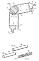
- the part circular wall segments 5 and 5' form strong bearing surfaces for supporting and guiding the part circular arms 8 and 8' in the hinging action while the part circular arms 8 and 8' themselves form hinge barrel elements to receive the hinge pin or pintle 24 which has a simple circular cross-section and when inserted into the hinge barrel formation presented by the arms 8 and 8' has its center centered on the median of the front and rear walls of the hinge members 1 and 1'.
- This combination provides an extremely effective free hinging movement and at the same time provides a hinge capable of withstanding forces tending to separate the hinge members in the operation of a large folding overhead garage door or the like.
- the hinge pintle 24 may simply be a longitudinal rod of circular section having a diameter to fit snuggly within the part circular arms 8 and 8' and it may be formed either as an extruded rod of high strength plastic material or it may be a metal bar.
- tubular pintle 24a of Figure 6 may be of extruded plastic or may be a tubular metal bar.
- the pintle 24b illustrated in Figure 7 is preferably extruded of high density polyethylene to provide a series of outwardly extending spokes or vanes 25 having only the tips thereof engaging the part circular arms 8 and 8'.
- the pintle 24b provides a minimum of friction and in effect is self-lubricating.
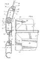
- FIG 8 illustrates how the panels 26 are removeably connected to the hinge elements 1 and 1' in the forming of an overhead garage door or the like.
- These panels 26 which preferably are formed of a suitable plastic material such as foamed PVC and may be plain panels or may be vacuum formed to provide any desired decorative design are adapted to seat in the case of the hinge element 1 on the shoulder 19.
- the panels are held against the wall 18 by a longitudinal extruded hollow bar stop 27 having a spear head 28 adapted to resiliently interengage with the restricted entrance 23.
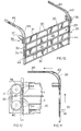
- a large garage door or the like will be made up of transverse rows of panels 26 while the hinge elements 1 and 1' extend the full width of the door generally designated at 29.
- Each of the panels 26 is removeably secured to intermediate members 30, top and bottom members 31 and 32, and side rails 33 respectively preferably in the same manner as the panels are secured to the longitudinal edges of the hinge members 1 and 1'.
- the side rails 33 are provided with projecting spines that are notched to present cog teeth 34 which are adapted to extend into door tracks 35 arranged at each side of the door 29.
- cog teeth 34 are adapted to be engaged by a suitable garage door opening mechanism here shown as a motor driven belt drive generally designated at 36 at each side of the door driven by small synchronous motors 37.
- a suitable garage door opening mechanism here shown as a motor driven belt drive generally designated at 36 at each side of the door driven by small synchronous motors 37.
- each motor 37 drives a belt 38 (only one being shown) through a drive sprocket 39 and idler sprocket 40, the belt having projecting cogs 41 which engage the cog teeth 34 of the edge frame bars or siderails 33 and projecting cogs 42 which engage the sprockets 39 and 40.
- the garage door tracks 35 as they curve as at 43 from the vertical section 44 to the horizontal section 45 are widened to accommodate the movement of the cog teeth 34 extending from the edges of the siderails 33 therethrough as the door panels 26 pivot relative to each other.
- door panels 26, the hinge members or bars 1 and 1', the top, bottom and siderails 31, 32 and 33 respectively all formed of suitable thermoplastic material may contain colour agents, ultraviolet light protecting agents and the like as will be understood by those skilled in the art.
- the invention provides for the production of large overhead doors which may be single or double garage doors which can be easily and inexpensively manufactured and easily assembled at a cost much lower than the conventional garage doors without requiring any of the extensive hardware of such doors. Moreover, their ability to be assembled in the field and their light weight which allows for easy handling, transporting and installing also enables the use of low torque garage opening mechanisms.
Landscapes
- Engineering & Computer Science (AREA)
- Civil Engineering (AREA)
- Structural Engineering (AREA)
- Mechanical Engineering (AREA)
- Extensible Doors And Revolving Doors (AREA)
- Hinges (AREA)
- Support Devices For Sliding Doors (AREA)
- Mechanical Pencils And Projecting And Retracting Systems Therefor, And Multi-System Writing Instruments (AREA)
- Forms Removed On Construction Sites Or Auxiliary Members Thereof (AREA)
- Extrusion Moulding Of Plastics Or The Like (AREA)
- Blow-Moulding Or Thermoforming Of Plastics Or The Like (AREA)
Claims (17)
- Elément de charnière (1 ou 1') destiné à être utilisé dans une liaison à charnière, ledit élément possédant :caractérisé en ce que :une paroi avant (2 ou 2') et une paroi arrière (3 ou 3') etprésentant, au niveau d'un bord une conformation de douille en forme générale de C (4 ou 4"),ladite conformation en forme de douille (4 ou 4") comportant :un premier segment de paroi de bord formé d'une partie de cercle (5 ou 5') qui s'étend avec une forme arquée à l'intérieur du bord de ladite paroi avant (2 ou 2') en direction de ladite paroi arrière (3 ou 3') et étant raccordée à cette dernière, etun second segment de bras particulièrement circulaire (8 ou 8') raccordé à une extrémité dudit premier segment de paroi formé d'une partie de cercle (5 ou 5'),lesdits premier et second segments formé d'une partie de cercle possédant un centre commun (10 ou 10');ledit élément est formé par extrusion d'une matière thermoplastique; en ce queune âme (9 ou 9'), qui s'étend vers l'intérieur dudit premier segment de paroi formé d'une partie de cercle (5 ou 5'), raccorde ledit second segment de paroi formé d'une partie de cercle (8 ou 8') au premier segment de paroi formé d'une partie de cercle; et en ce quele rayon (11 ou 11') de la surface intérieure dudit premier segment de paroi formé d'une partie de cercle (5 ou 5') est légèrement supérieur au rayon (13 ou 13') de la surface extérieure dudit second segment de bras formé d'une partie de cercle (8 ou 8').
- Elément de charnière selon la revendication 1, caractérisé en ce que ledit second segment de bras formé d'une partie de cercle (8) est raccordé par ladite âme (9) à l'extrémité dudit premier segment de paroi de bord formé d'une partie de cercle (5) au voisinage de ladite paroi arrière (30).
- Elément de charnière selon la revendication 1, caractérisé en ce que ledit second segment de bras formé d'une partie de cercle (8') est raccordé par ladite âme (9') à l'extrémité dudit premier segment de paroi de bord formé d'une partie de cercle (5') au niveau de ladite paroi avant (2').
- Elément de charnière selon l'une quelconque des revendications 1, 2 ou 3, caractérisé en ce que ladite âme (9 ou 9'), qui s'étend vers l'intérieur, forme un épaulement de butée au niveau de la jonction desdits premier et second segments en forme de parties de cercle.
- Elément de charnière selon l'une quelconque des revendications précédentes, caractérisé en ce que ledit premier segment de paroi de bord circulaire partiel (5 ou 5') est raccordé à ladite paroi arrière (3 ou 3') par une âme (6 ou 6') faisant un angle obtus avec ladite paroi arrière (3 ou 3').
- Couple d'éléments de charnière extrudés adaptés pour engrener entre eux partiellement en rotation pour leur utilisation dans la formation d'une liaison de charnière, chacun desdits éléments de charnière possédant :caractérisé en ce que :une paroi avant (2 ou 2') et une paroi arrière (3 ou 3') et chaque élément de charnière présentant, au niveau d'un bord :une configuration de douille en forme générale de C,lesdits éléments de charnière sont formés par extrusion d'une matière thermoplastique; en ce queladite configuration de douille en forme générale de C possède deux segments en forme de parties de cercle (5, 8 ou 5', 8') possédant un centre commun,l'un desdits segments formé d'une partie de cercle (5 ou 5') forme un segment de paroi de bord rentrant qui s'étend avec une forme courbe vers l'intérieur à partir du bord de ladite paroi avant (2 ou 2') jusqu'au voisinage de ladite paroi arrière (3 ou 3') et étant raccordé à ladite paroi arrière,l'autre desdits segments en forme de parties de cercle comprenant un bras formé d'une partie de cercle (8 ou 8') raccordé à une extrémité dudit segment de paroi formé d'une partie de cercle (5 ou 5') et s'incurvant vers l'extérieur au-delà desdites parois avant et arrière; en ce quelesdits deux segments en forme de parties de cercle (5, 8 ou 5', 8') possèdent des rayons différents, le rayon de la surface intérieure (11 ou 11') dudit segment de paroi formé d'une partie de cercle (5 ou 5') étant légèrement supérieur au rayon (13 ou 13') de la surface extérieure dudit segment de bras formé d'une partie de cercle (8 ou 8'); en ce quele segment de bras formé d'une partie de cercle (8) de l'un desdits éléments de charnière (1) est raccordé à son segment de paroi formé d'une partie de cercle (5) au voisinage de sa paroi arrière (3), et le segment de bras formé d'une partie de cercle (8') de l'autre desdits éléments de charnière (1') est raccordé à son segment de paroi formé d'une partie de cercle (5') au niveau de sa paroi avant (2'); et en ce quel'agencement étant tel quele segment de bras circulaire (8) dudit premier élément de charnière (1) est adapté pour tourner sur le segment de paroi formé d'une partie de cercle (5') dudit second élément de charnière (1') et vice versa, etlesdits deux segments de bras en forme de parties de cercle (8 et 8') sont adaptés pour former un cylindre de charnière servant à former un gond servant à recevoir un axe de charnière pour qu'ils puissent avoir un mouvement de rotation dans le gond.
- Couple d'éléments de charnière selon la revendication 6, caractérisé en ce que lesdites parois avant et arrière (2, 3, 2', 3') sont parallèles et ledit centre commun (10, 10') pour lesdits segments en forme de parties de cercle (5, 5', 8, 8') est situé sur une ligne s'étendant entre lesdites parois avant et arrière.
- Couple d'élément de charnière selon la revendication 6 ou la revendication 7, caractérisé en ce que le segment de bras formé d'une partie de cercle (8) dudit premier élément (1) est plus long que le segment de bras formé d'une partie de cercle (8') dudit second élément (1').
- Couple d'élément de charnière selon l'une quelconque des revendications 6, 7 ou 8, caractérisé en ce que les raccordements (9, 9') entre lesdits segments de paroi en forme de parties de cercle (5, 5') et lesdits segments de bras en forme de parties de cercle (8, 8') forment des rebords de butée.
- Porte repliable de garage ou analogue comprenant :caractérisée en ce queune pluralité de rangées transversales de panneaux de porte (26) raccordés d'une manière articulée par une pluralité de charnières transversales espacées,chacune desdites charnières transversales comprend un couple de tiges allongées creuses et extrudées de charnière (1, 1'),chacune desdites tiges de charnière possède une paroi avant (2 ou 2') et une paroi arrière (3 ou 3') et présentant, au niveau d'un bord, une configuration de douille en forme générale de C (4, 4'),lesdites tiges de charnière (1, 1') comportant des moyens s'étendant le long de leurs bords longitudinaux à l'opposé desdites configurations de douille en forme générale de C (4, 4') pour engrener avec lesdits panneaux de porte,lesdits panneaux de porte sont réalisés en matière plastique; en ce quechacune desdites tiges de charnière est formée d'une matière thermoplastique creuse allongée extrudée; en ce quechacune desdites configurations de douille en forme de C possède un segment formé d'une partie de cercle (5, 8 ou 5', 8') possédant un centre commun,l'un desdits segments formé d'une partie de cercle (5 ou 5') formant un segment de paroi de bord rentrant qui s'étend avec une forme incurvée vers l'intérieur à partir du bord de ladite paroi avant (2 ou 2') jusque dans une position adjacente à ladite paroi arrière (3 ou 3') et étant raccordé à ladite paroi arrière (3 ou 3'),l'autre desdits segments en forme de parties de cercle comprenant un bras formé d'une partie de cercle (8 ou 8') raccordé à une extrémité dudit segment de paroi formé d'une partie de cercle (5 ou 5') et s'incurvant vers l'extérieur au-delà desdites parois avant et arrière; en ce quechacun desdits deux segments en forme de parties de cercle (5, 8 ou 5', 8') possède des rayons différents, le rayon de la surface intérieure dudit segment de paroi formé d'une partie de cercle (5 ou 5') étant légèrement supérieur au rayon de la surface extérieure dudit segment de bras formé d'une partie de cercle (8 ou 8'); en ce queledit segment de bras formé d'une partie de cercle (8) d'une première desdites tiges de charnière (1) est raccordé audit segment de paroi formé d'une partie de cercle (5) au voisinage de ladite paroi arrière (2) dudit segment de bras formé d'une partie de cercle, et le segment de bras formé d'une partie de cercle (8') de l'autre desdites tiges de charnière étant connecté à son segment de paroi formé d'une partie de cercle (5') au niveau de sa paroi avant (2'); et en ce quel'agencement étant tel queledit segment de bras formé d'une partie de cercle (8) dudit premier tube de charnière (1) tourne sur ledit segment de paroi en forme de parties de cercle (5') dudit autre tube de charnière (1') et vice versa, etlesdits segments de bras en forme de parties de cercle (8, 8') forment un gond; et en ce queun axe de charnière (24, 24a, 24b) est monté dans ledit gond.
- Porte de garage selon la revendication 10, caractérisée en ce que lesdites parois avant et arrière (2, 2', 3, 3') sont parallèles et ledit centre commun (10, 10') pour lesdits segments en forme de parties de cercle (5, 5', 8, 8') est situé sur une ligne située entre lesdites parois avant et arrière.
- Porte de garage selon la revendication 10 ou la revendication 11, caractérisée en ce que lesdits segments de paroi en forme de parties de cercle (5, 5') desdites tiges de charnière (1, 1') sont raccordés à leurs parois arrière (3, 3') par des âmes (6, 6'), qui font un angle obtus avec lesdites parois arrière.
- Porte de garage selon l'une quelconque des revendications 10, 11 ou 12, caractérisée en ce que lesdits raccordements (9, 9') entre lesdits segments de paroi en forme de parties de cercle (5, 5') et lesdits segments de bras en forme de parties de cercle (8, 8') forment des rebords de butée.
- Porte de garage selon l'une quelconque des revendications 10 à 13, caractérisée en ce que ledit segment de bras formé d'une partie de cercle (8) dudit premier gond (1) est plus long que ledit segment de bras formé d'une partie de cercle (8') dudit autre gond (1').
- Porte de garage selon l'une quelconque des revendications 10 à 14, caractérisée en ce qu'avec les bords desdits panneaux (26) engrènent des rails de cadres de bords (33) présentant une série de dents saillantes (34) aptes à s'étendre dans une piste (55) dans une ouverture de porte.
- Porte de garage selon la revendication 15, caractérisée en ce que des moyens formant moteur (36) sont prévus pour faire engrener les vis dans lesdits rails de cadres de bords pour actionner la porte en vue de son ouverture et de sa fermeture.
- Porte de garage selon l'une quelconque des revendications 10 à 16, caractérisée en ce que ledit axe est une tige en polyéthylène (24b) comportant des ailettes (25), qui font saillie radialement et qui coopèrent avec les parois dudit gond (8, 8') de manière à former une charnière autolubrifiante.
Applications Claiming Priority (3)
| Application Number | Priority Date | Filing Date | Title |
|---|---|---|---|
| CA 2147199 CA2147199A1 (fr) | 1995-04-18 | 1995-04-18 | Elements extrudes articules et portes pliantes constituees de tels elements |
| CA2147199 | 1995-04-18 | ||
| PCT/CA1996/000218 WO1996033333A1 (fr) | 1995-04-18 | 1996-04-11 | Charnieres extrudees et portes repliables realisees avec des charnieres |
Publications (2)
| Publication Number | Publication Date |
|---|---|
| EP0821758A1 EP0821758A1 (fr) | 1998-02-04 |
| EP0821758B1 true EP0821758B1 (fr) | 1999-10-06 |
Family
ID=4155669
Family Applications (1)
| Application Number | Title | Priority Date | Filing Date |
|---|---|---|---|
| EP96908961A Expired - Lifetime EP0821758B1 (fr) | 1995-04-18 | 1996-04-11 | Charnieres extrudees et portes repliables realisees avec des charnieres |
Country Status (13)
| Country | Link |
|---|---|
| US (1) | US5915446A (fr) |
| EP (1) | EP0821758B1 (fr) |
| JP (1) | JPH11503799A (fr) |
| AT (1) | ATE185398T1 (fr) |
| AU (1) | AU710605B2 (fr) |
| BR (1) | BR9608090A (fr) |
| CA (1) | CA2147199A1 (fr) |
| DE (1) | DE69604581T2 (fr) |
| FI (1) | FI973834A7 (fr) |
| MX (1) | MX9708034A (fr) |
| NO (1) | NO974817L (fr) |
| NZ (1) | NZ304782A (fr) |
| WO (1) | WO1996033333A1 (fr) |
Families Citing this family (43)
| Publication number | Priority date | Publication date | Assignee | Title |
|---|---|---|---|---|
| AUPP269298A0 (en) | 1998-03-31 | 1998-04-23 | Clyde Industries Limited | Sectional overhead door with anti-pinch hinge |
| AU734088B2 (en) * | 1998-03-31 | 2001-05-31 | B&D Australia Pty Ltd | Hinge assembly for a sectional door |
| AT406701B (de) * | 1998-05-27 | 2000-08-25 | Famulus Elektrogeraete Gmbh | Lamelle für läden, z.b. rolläden |
| FR2779763B1 (fr) * | 1998-06-12 | 2000-08-11 | Fit Carrosserie | Porte sectionnelle de fermeture |
| US6339905B1 (en) * | 1998-07-20 | 2002-01-22 | Clark Craig | Hingeless, parallel storing, sectional aperture covering |
| JP2001132310A (ja) * | 1999-11-05 | 2001-05-15 | Matsushita Electric Ind Co Ltd | 扉 |
| US6189593B1 (en) | 2000-02-09 | 2001-02-20 | Cornell Iron Works, Inc. | Injection molded roll up security closure |
| US6499188B1 (en) * | 2000-10-17 | 2002-12-31 | Chun Lung Cheng | Case hinge structure |
| US6655442B2 (en) | 2001-09-19 | 2003-12-02 | Rite-Hite Holding Corporation | Sectional door with extruded panel members |
| US7040373B2 (en) * | 2001-09-19 | 2006-05-09 | Rite-Hite Holding Corp. | Extruded door panel members |
| US6772905B2 (en) * | 2001-11-23 | 2004-08-10 | Chun Lung Cheng | Protective case hinge structure |
| CA2383457A1 (fr) * | 2002-04-25 | 2003-10-25 | Royal Group Technologies Limited | Porte de garage modulaire |
| US20030235460A1 (en) * | 2002-05-09 | 2003-12-25 | Yong-Mo Moon | Displacement compliant joints |
| EP1736418A3 (fr) * | 2005-05-24 | 2007-02-14 | Fulvio Soncini | Charnière, notamment pour un boîtier |
| US20060273295A1 (en) * | 2005-06-01 | 2006-12-07 | Paul Maly | Extruded protective railing system |
| US7653969B2 (en) * | 2005-07-27 | 2010-02-02 | Taylor Made Group, Llc | Three-piece hinge |
| NL2000425C1 (nl) * | 2007-01-10 | 2008-07-11 | Xsplatforms | Brugmodule voor een hangbruginstallatie, alsmede hangbruginstallatie voorzien van de brugmodule. |
| US9416528B2 (en) | 2007-07-12 | 2016-08-16 | Schaffert Manufacturing Company, Inc. | Folding shed with portable feature |
| US8763315B2 (en) * | 2007-07-12 | 2014-07-01 | Morris L. Hartman | Folding shed |
| CA2695026A1 (fr) * | 2007-07-27 | 2009-02-05 | Upwardor Corporation | Portes en sections en composites polymeres et leur procede de fabrication |
| US20100053084A1 (en) * | 2008-08-27 | 2010-03-04 | Microsoft Corporation | Collapsible mouse with pinch-risk solution |
| US20110073723A1 (en) | 2009-09-25 | 2011-03-31 | Ashpole Benjamin C | Joint and foldable structures employing the same |
| DE202011000025U1 (de) * | 2011-01-06 | 2011-03-17 | SCHÜCO International KG | Blendschutz-Rollladen |
| US20130097939A1 (en) * | 2011-10-24 | 2013-04-25 | Charles C. Blume | Overlay Panel System for an Overhead Garage Door and Method of Installation |
| US8677713B1 (en) | 2013-03-06 | 2014-03-25 | Epi 04, Inc. | Extruded wall panel system and method of forming |
| EP3008258B1 (fr) * | 2013-06-14 | 2019-12-11 | DIRTT Environmental Solutions, Ltd. | Appareil, procédés et systèmes de liaison de panneaux et de modules de paroi |
| CN106458480B (zh) | 2014-05-02 | 2019-03-26 | 亚萨合莱自动门系统有限公司 | 用于自动控制装卸月台设备的系统及方法 |
| US20160138258A1 (en) * | 2014-11-19 | 2016-05-19 | Schaffert Manufacturing Company, Inc. | Folding shed |
| ES2653517T3 (es) | 2015-02-06 | 2018-02-07 | Masinara S.P.A. | Elemento de cierre para persiana de rodillo y pared móvil para persiana de rodillo que comprende el elemento de cierre |
| US11305953B2 (en) | 2016-05-03 | 2022-04-19 | Assa Abloy Entrance Systems Ab | Control systems for operation of loading dock equipment, and associated methods of manufacture and use |
| US11225824B2 (en) | 2016-05-03 | 2022-01-18 | Assa Abloy Entrance Systems Ab | Control systems for operation of loading dock equipment, and associated methods of manufacture and use |
| US11256264B2 (en) | 2017-08-30 | 2022-02-22 | Assa Abloy Entrance Systems Ab | Vehicle guidance systems and associated methods of use at logistics yards and other locations |
| US10494205B1 (en) | 2018-12-06 | 2019-12-03 | Assa Abloy Entrance Systems Ab | Remote loading dock authorization systems and methods |
| US11142413B2 (en) | 2019-01-28 | 2021-10-12 | Assa Abloy Entrance Systems Ab | Systems and methods for automated loading and unloading at a dock station |
| US11262747B2 (en) | 2019-06-11 | 2022-03-01 | Assa Abloy Entrance Systems Ab | Vehicle identification and guidance systems and associated methods |
| DE102019125204A1 (de) * | 2019-09-19 | 2021-03-25 | Seuster Kg | Rolltor |
| ES3035777T3 (en) * | 2021-03-17 | 2025-09-09 | Birkigt S L | Shutter systems |
| US12570129B2 (en) | 2021-06-02 | 2026-03-10 | Assa Abloy Entrance Systems Ab | Loading dock automated trailer door systems |
| SE2130325A1 (en) * | 2021-06-02 | 2022-12-03 | Assa Abloy Entrance Systems Ab | Loading dock automated trailer door systems |
| WO2023274744A2 (fr) | 2021-07-02 | 2023-01-05 | Assa Abloy Entrance Systems Ab | Systèmes de remorque motorisés |
| US12400175B2 (en) | 2021-11-30 | 2025-08-26 | Assa Abloy Entrance Systems Ab | Trailer validation systems |
| JP2024025465A (ja) * | 2022-08-12 | 2024-02-26 | 文化シヤッター株式会社 | 開閉装置 |
| US20240060356A1 (en) * | 2022-08-16 | 2024-02-22 | Overhead Door Corporation | Modular barrier panel frame reinforcement systems and methods |
Family Cites Families (7)
| Publication number | Priority date | Publication date | Assignee | Title |
|---|---|---|---|---|
| US2968829A (en) * | 1958-04-08 | 1961-01-24 | Weather Seal Inc | Hinge with arcuate plastic hinge connector |
| US3359594A (en) * | 1965-04-02 | 1967-12-26 | Pastoor Beno Johannes | Folding closures |
| US4475268A (en) * | 1981-12-16 | 1984-10-09 | Martinray Industries Ltd. | Closure hinge improvements |
| US4532973A (en) * | 1983-06-15 | 1985-08-06 | Defalco Ralph | Overhead door construction |
| US4567931A (en) * | 1983-10-03 | 1986-02-04 | Uneek Cap And Door, Inc. | Sectional door and components thereof |
| DE3538947A1 (de) * | 1985-11-02 | 1987-05-21 | Alten K | Tor, insb. sektionaltor, fuer gebaeude od.dgl. |
| FR2633005B2 (fr) * | 1987-07-28 | 1991-08-16 | Peyrichou Malan Sa | Tablier de porte en polycarbonate a sections horizontales |
-
1995
- 1995-04-18 CA CA 2147199 patent/CA2147199A1/fr not_active Abandoned
-
1996
- 1996-04-11 US US08/930,980 patent/US5915446A/en not_active Expired - Fee Related
- 1996-04-11 DE DE69604581T patent/DE69604581T2/de not_active Expired - Fee Related
- 1996-04-11 JP JP53136696A patent/JPH11503799A/ja active Pending
- 1996-04-11 BR BR9608090A patent/BR9608090A/pt not_active Application Discontinuation
- 1996-04-11 AU AU52648/96A patent/AU710605B2/en not_active Ceased
- 1996-04-11 AT AT96908961T patent/ATE185398T1/de not_active IP Right Cessation
- 1996-04-11 NZ NZ30478296A patent/NZ304782A/xx unknown
- 1996-04-11 MX MX9708034A patent/MX9708034A/es not_active Application Discontinuation
- 1996-04-11 EP EP96908961A patent/EP0821758B1/fr not_active Expired - Lifetime
- 1996-04-11 WO PCT/CA1996/000218 patent/WO1996033333A1/fr not_active Ceased
-
1997
- 1997-09-29 FI FI973834A patent/FI973834A7/fi unknown
- 1997-10-17 NO NO974817A patent/NO974817L/no unknown
Also Published As
| Publication number | Publication date |
|---|---|
| BR9608090A (pt) | 1999-02-23 |
| NO974817L (no) | 1997-10-20 |
| WO1996033333A1 (fr) | 1996-10-24 |
| AU710605B2 (en) | 1999-09-23 |
| FI973834A7 (fi) | 1997-11-19 |
| ATE185398T1 (de) | 1999-10-15 |
| CA2147199A1 (fr) | 1996-10-19 |
| DE69604581T2 (de) | 2000-02-10 |
| NO974817D0 (no) | 1997-10-17 |
| FI973834A0 (fi) | 1997-09-29 |
| US5915446A (en) | 1999-06-29 |
| EP0821758A1 (fr) | 1998-02-04 |
| NZ304782A (en) | 1999-03-29 |
| MX9708034A (es) | 1998-02-28 |
| JPH11503799A (ja) | 1999-03-30 |
| AU5264896A (en) | 1996-11-07 |
| DE69604581D1 (de) | 1999-11-11 |
Similar Documents
| Publication | Publication Date | Title |
|---|---|---|
| US5915446A (en) | Extruded hinge members and folding doors formed therefrom | |
| MXPA97008034A (en) | Extruded hinge members and folding doors formed from mis | |
| US5365993A (en) | Sectional door | |
| US5737802A (en) | Door track | |
| AU648106B2 (en) | Sectional doors and compressible flexible hinge assemblies | |
| US5036899A (en) | Panel garage door opening and closing | |
| EP0610263B1 (fr) | Systeme d'articulation pour mobiles/coulissants battants | |
| US5564164A (en) | Sectional door panel hinge | |
| US5394924A (en) | Closure element for an aperture | |
| US6363993B1 (en) | Pivoting bracket for connecting articulated door panels | |
| EP1336712A1 (fr) | Réalisation de porte de garage | |
| IE893841L (en) | Door | |
| AU2003257534B2 (en) | Improvements To Roller Shutters | |
| SI20219A (sl) | Konstrukcija garažnih vrat iz plošč | |
| AU642141B2 (en) | Sectional doors and flexible hinge assemblies | |
| KR102182602B1 (ko) | 접이식 도어시스템 | |
| AU706873B2 (en) | Folding garage doors and the like and hinges therefor | |
| US3457983A (en) | Upwardly acting door structure | |
| US2311703A (en) | Flexible door and mechanism for operating the same | |
| CN1187231A (zh) | 挤压成型的铰接部件和由此形成的折叠门 | |
| US20060180282A1 (en) | Building door consisting of serveral mutually articulated panels | |
| CN108442839B (zh) | 一种上排挂门 | |
| JP2902267B2 (ja) | 縦型ブラインド | |
| WO1996023948B1 (fr) | Portes pliantes de garage et analogue et leurs charnieres | |
| KR102667905B1 (ko) | 미닫이용 소음 방지시스템 |
Legal Events
| Date | Code | Title | Description |
|---|---|---|---|
| PUAI | Public reference made under article 153(3) epc to a published international application that has entered the european phase |
Free format text: ORIGINAL CODE: 0009012 |
|
| 17P | Request for examination filed |
Effective date: 19971105 |
|
| AK | Designated contracting states |
Kind code of ref document: A1 Designated state(s): AT BE CH DE DK ES FI FR GB GR IE IT LI LU MC NL PT SE |
|
| 17Q | First examination report despatched |
Effective date: 19980302 |
|
| GRAG | Despatch of communication of intention to grant |
Free format text: ORIGINAL CODE: EPIDOS AGRA |
|
| GRAG | Despatch of communication of intention to grant |
Free format text: ORIGINAL CODE: EPIDOS AGRA |
|
| GRAH | Despatch of communication of intention to grant a patent |
Free format text: ORIGINAL CODE: EPIDOS IGRA |
|
| GRAH | Despatch of communication of intention to grant a patent |
Free format text: ORIGINAL CODE: EPIDOS IGRA |
|
| GRAA | (expected) grant |
Free format text: ORIGINAL CODE: 0009210 |
|
| AK | Designated contracting states |
Kind code of ref document: B1 Designated state(s): AT BE CH DE DK ES FI FR GB GR IE IT LI LU MC NL PT SE |
|
| PG25 | Lapsed in a contracting state [announced via postgrant information from national office to epo] |
Ref country code: FR Free format text: LAPSE BECAUSE OF FAILURE TO SUBMIT A TRANSLATION OF THE DESCRIPTION OR TO PAY THE FEE WITHIN THE PRESCRIBED TIME-LIMIT Effective date: 19991006 Ref country code: SE Free format text: THE PATENT HAS BEEN ANNULLED BY A DECISION OF A NATIONAL AUTHORITY Effective date: 19991006 Ref country code: NL Free format text: LAPSE BECAUSE OF FAILURE TO SUBMIT A TRANSLATION OF THE DESCRIPTION OR TO PAY THE FEE WITHIN THE PRESCRIBED TIME-LIMIT Effective date: 19991006 Ref country code: IT Free format text: LAPSE BECAUSE OF FAILURE TO SUBMIT A TRANSLATION OF THE DESCRIPTION OR TO PAY THE FEE WITHIN THE PRESCRIBED TIME-LIMIT;WARNING: LAPSES OF ITALIAN PATENTS WITH EFFECTIVE DATE BEFORE 2007 MAY HAVE OCCURRED AT ANY TIME BEFORE 2007. THE CORRECT EFFECTIVE DATE MAY BE DIFFERENT FROM THE ONE RECORDED. Effective date: 19991006 Ref country code: GR Free format text: LAPSE BECAUSE OF NON-PAYMENT OF DUE FEES Effective date: 19991006 Ref country code: FI Free format text: LAPSE BECAUSE OF NON-PAYMENT OF DUE FEES Effective date: 19991006 Ref country code: ES Free format text: THE PATENT HAS BEEN ANNULLED BY A DECISION OF A NATIONAL AUTHORITY Effective date: 19991006 Ref country code: BE Free format text: LAPSE BECAUSE OF FAILURE TO SUBMIT A TRANSLATION OF THE DESCRIPTION OR TO PAY THE FEE WITHIN THE PRESCRIBED TIME-LIMIT Effective date: 19991006 Ref country code: AT Free format text: LAPSE BECAUSE OF FAILURE TO SUBMIT A TRANSLATION OF THE DESCRIPTION OR TO PAY THE FEE WITHIN THE PRESCRIBED TIME-LIMIT Effective date: 19991006 |
|
| REF | Corresponds to: |
Ref document number: 185398 Country of ref document: AT Date of ref document: 19991015 Kind code of ref document: T |
|
| REG | Reference to a national code |
Ref country code: CH Ref legal event code: NV Representative=s name: SCHMAUDER & PARTNER AG PATENTANWALTSBUERO Ref country code: CH Ref legal event code: EP |
|
| REF | Corresponds to: |
Ref document number: 69604581 Country of ref document: DE Date of ref document: 19991111 |
|
| PG25 | Lapsed in a contracting state [announced via postgrant information from national office to epo] |
Ref country code: PT Free format text: LAPSE BECAUSE OF FAILURE TO SUBMIT A TRANSLATION OF THE DESCRIPTION OR TO PAY THE FEE WITHIN THE PRESCRIBED TIME-LIMIT Effective date: 20000106 Ref country code: DK Free format text: LAPSE BECAUSE OF FAILURE TO SUBMIT A TRANSLATION OF THE DESCRIPTION OR TO PAY THE FEE WITHIN THE PRESCRIBED TIME-LIMIT Effective date: 20000106 |
|
| REG | Reference to a national code |
Ref country code: IE Ref legal event code: FG4D |
|
| NLV1 | Nl: lapsed or annulled due to failure to fulfill the requirements of art. 29p and 29m of the patents act | ||
| EN | Fr: translation not filed | ||
| PG25 | Lapsed in a contracting state [announced via postgrant information from national office to epo] |
Ref country code: LU Free format text: LAPSE BECAUSE OF NON-PAYMENT OF DUE FEES Effective date: 20000411 Ref country code: IE Free format text: LAPSE BECAUSE OF NON-PAYMENT OF DUE FEES Effective date: 20000411 Ref country code: GB Free format text: LAPSE BECAUSE OF NON-PAYMENT OF DUE FEES Effective date: 20000411 |
|
| PG25 | Lapsed in a contracting state [announced via postgrant information from national office to epo] |
Ref country code: LI Free format text: LAPSE BECAUSE OF NON-PAYMENT OF DUE FEES Effective date: 20000430 Ref country code: CH Free format text: LAPSE BECAUSE OF NON-PAYMENT OF DUE FEES Effective date: 20000430 |
|
| PLBE | No opposition filed within time limit |
Free format text: ORIGINAL CODE: 0009261 |
|
| STAA | Information on the status of an ep patent application or granted ep patent |
Free format text: STATUS: NO OPPOSITION FILED WITHIN TIME LIMIT |
|
| 26N | No opposition filed | ||
| PG25 | Lapsed in a contracting state [announced via postgrant information from national office to epo] |
Ref country code: MC Free format text: LAPSE BECAUSE OF NON-PAYMENT OF DUE FEES Effective date: 20001031 |
|
| GBPC | Gb: european patent ceased through non-payment of renewal fee |
Effective date: 20000411 |
|
| REG | Reference to a national code |
Ref country code: CH Ref legal event code: PL |
|
| PG25 | Lapsed in a contracting state [announced via postgrant information from national office to epo] |
Ref country code: DE Free format text: LAPSE BECAUSE OF NON-PAYMENT OF DUE FEES Effective date: 20010201 |
|
| REG | Reference to a national code |
Ref country code: IE Ref legal event code: MM4A |