EP0821774B1 - Wellendichtung - Google Patents
Wellendichtung Download PDFInfo
- Publication number
- EP0821774B1 EP0821774B1 EP96910114A EP96910114A EP0821774B1 EP 0821774 B1 EP0821774 B1 EP 0821774B1 EP 96910114 A EP96910114 A EP 96910114A EP 96910114 A EP96910114 A EP 96910114A EP 0821774 B1 EP0821774 B1 EP 0821774B1
- Authority
- EP
- European Patent Office
- Prior art keywords
- seal
- shaft
- ring
- sealing
- sealing ring
- Prior art date
- Legal status (The legal status is an assumption and is not a legal conclusion. Google has not performed a legal analysis and makes no representation as to the accuracy of the status listed.)
- Expired - Lifetime
Links
- 238000007789 sealing Methods 0.000 claims abstract description 104
- 239000012530 fluid Substances 0.000 claims abstract description 9
- 241001272720 Medialuna californiensis Species 0.000 claims abstract description 4
- 239000007789 gas Substances 0.000 description 9
- 238000000926 separation method Methods 0.000 description 9
- 230000033001 locomotion Effects 0.000 description 8
- 230000000694 effects Effects 0.000 description 4
- 239000004809 Teflon Substances 0.000 description 3
- 229920006362 Teflon® Polymers 0.000 description 3
- 238000000034 method Methods 0.000 description 3
- XKRFYHLGVUSROY-UHFFFAOYSA-N Argon Chemical compound [Ar] XKRFYHLGVUSROY-UHFFFAOYSA-N 0.000 description 2
- IJGRMHOSHXDMSA-UHFFFAOYSA-N Atomic nitrogen Chemical compound N#N IJGRMHOSHXDMSA-UHFFFAOYSA-N 0.000 description 2
- 230000006835 compression Effects 0.000 description 2
- 238000007906 compression Methods 0.000 description 2
- 230000007423 decrease Effects 0.000 description 2
- 230000003247 decreasing effect Effects 0.000 description 2
- 238000009434 installation Methods 0.000 description 2
- 238000005461 lubrication Methods 0.000 description 2
- VNWKTOKETHGBQD-UHFFFAOYSA-N methane Chemical compound C VNWKTOKETHGBQD-UHFFFAOYSA-N 0.000 description 2
- 230000008569 process Effects 0.000 description 2
- 230000009467 reduction Effects 0.000 description 2
- 238000013022 venting Methods 0.000 description 2
- OKTJSMMVPCPJKN-UHFFFAOYSA-N Carbon Chemical compound [C] OKTJSMMVPCPJKN-UHFFFAOYSA-N 0.000 description 1
- 239000003570 air Substances 0.000 description 1
- 229910052786 argon Inorganic materials 0.000 description 1
- 230000004888 barrier function Effects 0.000 description 1
- 230000005540 biological transmission Effects 0.000 description 1
- 229910052799 carbon Inorganic materials 0.000 description 1
- 230000006837 decompression Effects 0.000 description 1
- 230000001419 dependent effect Effects 0.000 description 1
- 238000005516 engineering process Methods 0.000 description 1
- 230000020169 heat generation Effects 0.000 description 1
- 239000001257 hydrogen Substances 0.000 description 1
- 229910052739 hydrogen Inorganic materials 0.000 description 1
- 125000004435 hydrogen atom Chemical class [H]* 0.000 description 1
- 238000004519 manufacturing process Methods 0.000 description 1
- 239000000463 material Substances 0.000 description 1
- 239000003345 natural gas Substances 0.000 description 1
- 229910052757 nitrogen Inorganic materials 0.000 description 1
- 229920000642 polymer Polymers 0.000 description 1
- 238000005086 pumping Methods 0.000 description 1
- 230000002441 reversible effect Effects 0.000 description 1
- 230000001052 transient effect Effects 0.000 description 1
Images

Classifications
-
- F—MECHANICAL ENGINEERING; LIGHTING; HEATING; WEAPONS; BLASTING
- F16—ENGINEERING ELEMENTS AND UNITS; GENERAL MEASURES FOR PRODUCING AND MAINTAINING EFFECTIVE FUNCTIONING OF MACHINES OR INSTALLATIONS; THERMAL INSULATION IN GENERAL
- F16J—PISTONS; CYLINDERS; SEALINGS
- F16J15/00—Sealings
- F16J15/16—Sealings between relatively-moving surfaces
- F16J15/34—Sealings between relatively-moving surfaces with slip-ring pressed against a more or less radial face on one member
- F16J15/3464—Mounting of the seal
-
- F—MECHANICAL ENGINEERING; LIGHTING; HEATING; WEAPONS; BLASTING
- F16—ENGINEERING ELEMENTS AND UNITS; GENERAL MEASURES FOR PRODUCING AND MAINTAINING EFFECTIVE FUNCTIONING OF MACHINES OR INSTALLATIONS; THERMAL INSULATION IN GENERAL
- F16J—PISTONS; CYLINDERS; SEALINGS
- F16J15/00—Sealings
- F16J15/16—Sealings between relatively-moving surfaces
- F16J15/34—Sealings between relatively-moving surfaces with slip-ring pressed against a more or less radial face on one member
-
- Y—GENERAL TAGGING OF NEW TECHNOLOGICAL DEVELOPMENTS; GENERAL TAGGING OF CROSS-SECTIONAL TECHNOLOGIES SPANNING OVER SEVERAL SECTIONS OF THE IPC; TECHNICAL SUBJECTS COVERED BY FORMER USPC CROSS-REFERENCE ART COLLECTIONS [XRACs] AND DIGESTS
- Y10—TECHNICAL SUBJECTS COVERED BY FORMER USPC
- Y10S—TECHNICAL SUBJECTS COVERED BY FORMER USPC CROSS-REFERENCE ART COLLECTIONS [XRACs] AND DIGESTS
- Y10S277/00—Seal for a joint or juncture
- Y10S277/91—O-ring seal
Definitions
- the invention relates to a shaft seal for rotating shafts in turbo-machines, in particular but not exclusively to non-contacting shaft seals.
- This type of shaft seal is often used with machinery for the pumping of gas (nitrogen, argon, hydrogen, natural gas, air, etc.) where the transmission of gas along the shaft needs to be prevented.
- gas nitrogen, argon, hydrogen, natural gas, air, etc.
- the shaft seals may be non-contact type seals, in order to reduce heat build up in the seals and the wear of the sealing parts.
- Non-contacting operation avoids this undesirable face contact when the shaft is rotating above a certain minimum speed, which is often called a lift-off speed.
- Non-contacting shaft seals provide advantages over seals where the sealing surfaces contact one another due to reduction in wear and the lower heat generation.
- Articles entitled “Fundamentals of Spiral Groove Non-contacting Face Seals” by Gabriel, Ralph P. (Journal of American Society of Lubrication Engineers Volume 35, 7, pages 367-375, and “Improved Performance of Film-Riding Gas Seals Through Enhancement of Hydrodynamic Effects” by Sedy, Joseph (Transactions of the American Society of Lubrication Engineers, Volume 23, 1 pages 35-44) describe non-contacting seal technology and design criteria and are incorporated herein by reference.
- a non-contacting face seal consists of two sealing rings, each of which is provided with a very precisely finished sealing surface.
- Both rings are positioned adjacent to each other with the sealing surfaces in contact at conditions of zero pressure differential and zero speed of rotation.
- One of the rings is normally fixed to the rotatable shaft by means of a shaft sleeve, the other is located within the seal housing structure and allowed to move axially.
- a sealing member is placed between the ring and the housing. This sealing member must permit some sliding motion while under pressure, therefore normally a top quality O-ring is selected for that duty. This O-ring is often called the secondary seal.
- one of the two sealing surfaces in contact is provided with shallow surface recesses, which act to generate pressure fields that force two sealing surfaces apart.
- the character of the separation forces is such that their magnitude decreases with the increase of face separation.
- Opposing or closing forces depend on sealed pressure level and as such are independent of face separation. They result from the sealed pressure and the spring force acting on the back surface of the axially movable sealing ring.
- Turbocompressors are used to compress this fluid and since gas has a relatively low mass, they normally operate at very high speeds and with a number of compression stages in series.
- the aim is to achieve the greatest degree of sealing in the space available.
- one crucial factor is the radial extent of the primary seal.
- the rotary sealing ring is prevented from axial movement locating the sealing ring between a radial flange of an inner sleeve to which it is fixed for rotation with the shaft and an axial locking sleeve surrounding the inner sleeve abutting the sealing face of the sealing ring.
- the present invention seeks to provide a shaft seal in which a greater sealing effect is provided.
- a shaft seal comprising a sealing element juxtaposed to a rotary sealing ring mounted on an inner sleeve for fitting around the shaft, characterised in that a socket being provided extending from inside the sleeve radially outwards into the sealing ring, and a locking member adapted to be fitted into the socket to lock the sealing ring axially and rotationally fast on the sleeve.
- an arrangement arranged to fit to a shaft seal comprising a sealing ring, an inner sleeve and a locking member, wherein the sealing ring is adapted to fit around the inner sleeve with a socket extending radially outwards from the inside of the shaft sleeve into the sealing ring and the locking member being arranged to fit into the socket to lock the sealing ring axially and rotationally fast to the inner sleeve.
- the diameter of the primary seal faces can be increased because the radial space is no longer taken by the axial-locking sleeve previously used for axially locking the rotary ring and/or the shroud portion of the inner sleeve which extends axially outside the outside diameter of the primary seal from which pins drive and/or axially lock the rotary ring.
- the locking member extends through an axially extending face of the rotary ring, the present invention can be applied to reversible rotary sealing rings. This invention can be retro-fitted to an existing shaft seal.
- the socket(s) may extend completely through the inner sleeve.
- a tolerance ring extending around the shaft holds the locking member in the socket.
- the socket is formed through the ring/sleeve when these parts are fixed together to ensure reliable locking by the locking member.
- the locking member are half-moon (semi-circular). This provides smoother force transmittal to reduce unbalancing forces affecting the shaft seal.
- the sleeve includes a flange portion extending radially outwards, but does not include a shroud portion extending axially from the outside of the flange portion.
- a larger primary seal can be fitted into the same housing as the prior art without the use of a axial locking sleeve.
- the present invention is fitted to a shaft seal in which the sealing element is mounted co-axially to the sealing ring to form a primary seal between opposed faces thereof to substantially prevent fluid flow across the primary seal from a high-pressure radial side to a low-pressure radial side, the sealing element being urged axially towards the rotary ring by a biasing means acting between a pusher sleave connected to the sealing element and a seal housing with a secondary sleave formed therebetween by a sealing member located in a channel in the part on the low-pressure radial side.
- the primary seal By providing the secondary sealing member in the part radially distant from the high pressure source, the primary seal quickly provides an effective barrier. Further, during start-up of the seal, the problem of seal face hang-up is greatly reduced or even eliminated.
- the inventor considers that the improvements due when the secondary sealing member slides axially during start-up of the machine, the frictional engagement of the seal member with the pusher sleeve and housing surfaces, alters the balance diameter of the shaft seal to where the frictional engagement occurs. Consequently, due to the sealing member being located in the low pressure side, the balance diameter is altered towards providing increasing the closing force in the primary seal. Normally, the friction between the housing and pusher sleeve would be aligned along the equilibrium balance diameter of the shaft seal.
- This invention is particularly applicable to non-contact seals.
- the pusher sleeve is a L-shaped part separate from the sealing element.
- the spring biasing means acts between the housing and one leg of the L-shaped sleeve parallel to the back face of the sealing element.
- the secondary sealing is formed between a face of the housing and the other leg of the L-shaped sleeve.
- the other leg of the sleeve is radially inward of the housing.
- a further seal is provided by an 0-ring between the pusher sleeve and the sealing element, wherein the further seal 0-ring is located in a half dovetail channel.
- the further O-ring is provided between the pusher sleeve and the sealing element in a square cut or dovetail channel provided in the sleeve.
- the dove-tailed channel is often used so that the 0-ring can be reliably installed in the seal.
- the seal is often blown out of the channel due to pressure build up in the dove-tailed channel which cannot otherwise be vented.
- the preferred half dove-tailed shape allows a limited movement of the 0-ring allowing pressure to escape from the channel. Due to the very high cost associated with the seal strip down, this design is particularly advantageous.
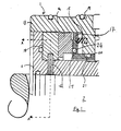
- the invention provides a shaft seal 1 about a shaft 2.
- a shaft seal 1 is provided about a shaft 2.
- two shaft seals are provided in tandem along the second (downstream) seal forming a backup to the first seal on a shaft of a compressor, turbine or other pressurised machine.
- the seal 1 includes a rotary sealing ring 10 mounted about the shaft 2 radially outwards of an inner sleeve 11 mounted about the shaft 2.
- the inner sleeve 11 is coupled for rotation and axial locking with the shaft 2 and the sealing ring 10 is coupled for rotation to the inner sleeve 11 by means of a plurality of locking members 12, each of which extends through an associated socket formed by aligned slots in the sealing ring 10 and the inner sleeve 11.
- the inner sleeve 11 includes a radial flange.
- the locking members 12 also prevent axial movement of the sealing ring 10.
- the socket is formed in the sleeve/ring at the same time to ensure a reliable alignment of the slots in the respective parts.
- a tolerance ring 18 extends about the shaft 2 between the locking members 12 and the shaft 2.
- the locking members 12 are preferably half-moon shaped. This reduces the rotational drive producing forces which unbalance the shaft seal.
- This arrangement of the sealing ring 10 on the inner sleeve 11 provides a smaller outside diameter to the primary seal compared to prior known seals producing the same sealing effect.
- the stresses produced in the seal 1 are lower, the weight of the seal is less and hence the leakage of the seal 1 is lowered.
- a rotationally stationary sealing element 14 is mounted juxtaposed to the sealing ring 10.
- a primary seal is formed between radially extending sealing faces of the sealing ring 10 and the sealing element 14 opposed to one another.
- the sealing face of the sealing element 14 having shallow grooves cut into the front surface thereof to generate the required separation between the sealing faces.
- the grooves could alternatively be formed in the rotary sealing ring 10 (as shown in Fig.3).
- the sealing element 14 is normally made from carbon or other suitable material.
- the sealing element 14 is biased axially towards the sealing ring 10 by spring means 15 (shown partly in dotted outline.
- the sealing element 14 has a limited axial movement.
- Spring means 15 normally comprises a plurality (e.g. six) springs located about the shaft 2.
- the springs 15 provide relatively little force (typically about 50 N) compared to the separating forces generated by the seal when in use, but are enough to move the sealing faces into contact under no pressure conditions.
- the spring 15 acts through L-shaped pusher sleeve 17 to urge the back face of the sealing element 14 axially towards the sealing ring 10.
- the spring 15 acts against an inward radially flange of housing 19 of the seal 1.
- a high pressure gas is supplied from the housing 19 to the radially outer edge of the sealing ring 10 and the sealing element 14.
- This gas is normally a clean gas suitable for venting into the atmosphere rather than the working fluid of the machine, in which case the leakage can be piped to burn (flare).
- the high pressure extends across the sealing face of the sealing element 14 and around the back face thereof. Secondary seals are provided to prevent the high pressure venting around the sealing element 14.
- a first secondary seal is formed by 0-ring 20 between the pusher sleeve 17 and the inwardly extending radial flange of the housing 19.
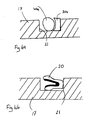
- Figs. 4a and 4b show alternative arrangements of the first secondary seal.
- Fig. 4a shows a first alternative where the first secondary seal is formed by an O-ring 20a and a back-up ring 20b.
- the back-up ring 20b can be made from e.g. Teflon, and is located on the low-pressure side of channel 21.
- Fig. 4b shows a second alternative where the first secondary seal is formed by a spring energised polymer seal 20.
- the 0-ring 20 is located in a channel 21 formed in the axially extending leg of the L-shaped pusher sleeve 17.
- the O-ring seals against the axially extending face of the radial flange of the housing 19.
- the adjacent faces of the pusher sleeve 17 and the radial flange of the housing 19 extends substantially along a line at the equilibrium balance diameter for the seal when operating at its equilibrium made.
- the pusher sleeve leg is radially inwards from the radial flange of the housing 19 the effect of frictional engagement of the 0-ring will only cause the balance diameter to decrease because the frictional engagement is either on or inside the equilibrium balance diameter. Reducing the actual balance diameter increases closing force on the primary seal.
- the equilibrium balance diameter is set to 150.8 mm at which a closing force of 400 to 500 N is generated at the primary seal.
- the first secondary seal 0-ring 20 has a radial extent of about 3.5 mm (when new). If the frictional engagement between the 0-ring 20 tended to increase the actual balance diameter during sliding movement with the O-ring 20, i.e. the prior art circumstance, the balance diameter could be increased to a maximum of 157.8 mm. At this balance diameter there is a net opening force on the primary seal of about 12000 N. This example assumes the case where the O-ring 20 fails to move in the channel 21. Normally, the 0-ring 20 would have moved under lower pressures, but still the net opening force could be higher than the closing force of the springs (which is typically in the region of 50 N).
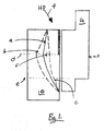
- FIG.3 shows a schematic pressure profile overlaid on the primary seal of the shaft seal 1.
- the distance between the sealing ring 10 and the sealing element 14 has been exaggerated for illustrative purposes.
- the block headed arrow 30 depicts the high pressure source on the outside diameter of the seal.
- Line a represents the pressure profile generated with the seal 1 running at stable conditions.
- the highest pressure is generated at the radially-inward end of the grooves (shown in this case on sealing ring 10) illustrated as line d.
- this pressure is greater in stable running conditions shown as line a than the pressure at point f which corresponds to the opening pressure.
- the balance diameter is shown for this stable condition as line e, the equilibrium balance diameter.
- Line b illustrates the present invention, showing the pressure profile during start-up of the machine.
- the closing force illustrated by line b is higher than the stable-running pressure, line a, because the distance between the sealing ring 10 and the sealing element 14 is less. The seal is thus driven to its stable running conditions regardless of the frictional engagement of the 0-ring 20.
- Line c illustrates the prior art situation where the 0-ring sticks and increases the balance diameter generated at start-up. Because the closing force never overcomes the opening force (H.P.) the seal is blown open and as will be appreciated, enough force is not generated to allow the primary seal to form.
- H.P. opening force
- the equivalent O-ring of the first secondary seal can be located in a channel in the part radially outside the equilibrium balance diameter. In this case, the frictional engagement of the O-ring will tend to increase the actual balance diameter, which will again tend to increase the closing force generated at the primary seal.
- the illustrated embodiment shows the 0-ring 20 in the channel 21. This could be supplemented by a back-up ring, e.g. made from Teflon, on the low-pressure side of channel 21.
- a back-up ring e.g. made from Teflon
- a further secondary seal is also formed between the back face of sealing element 14 and the radially-extending leg of pusher sleeve 15.
- 0-ring 24 is located in a channel 25 formed in the pusher sleeve 15 (but alternatively could be formed in the back face of the sealing element 14).
- the channel 25 is a half dove-tail channel. This shape of channel 25 prevents a pressure build up in the channel 25 which leads to the 0-ring 24 being blown out of the channel 25 during rapid depressurisation of the machine or other transient conditions.
- This shape of channel 25 could be used advantageously in all shaft seals housing using a similarly placed secondary seal.
- tandem seals 1 are used along a shaft 2 with the second seal 1 acting as a back up to the first seal.
- One or more further seals could also be provided along the shaft if required.
Landscapes
- Engineering & Computer Science (AREA)
- General Engineering & Computer Science (AREA)
- Mechanical Engineering (AREA)
- Sealing Devices (AREA)
- Mechanical Sealing (AREA)
- Sealing With Elastic Sealing Lips (AREA)
Claims (10)
- Wellendichtung (1) mit einem Dichtungselement (14), welches neben einem Rotationsdichtungsring (10) angebracht ist, der zur Passung um die Welle (2) auf einer Innenbuchse (11) angordnet ist, dadurch gekennzeichnet, dass eine vom Innern der Buchse (11) nach außen in den Dichtungsring (10) sich erstreckende Überschiebmuffe sowie zur achsrichtungs- und drehfesten Blockierung des Dichtungsrings (10) auf der Buchse (11) ein in die Überschiebmuffe passendes Blockierungselement (12) vorgesehen sind.
- Anordnung für eine Wellendichtung (1) mit einem Dichtungsring (10), einer Innenbuchse (11) und einem Blockierungselement (12), in welcher der Dichtungsring so beschaffen ist, dass er um die Innenbuchse (11) paßt, mit einer sich vom Innern der Wellenbuchse (11) radial nach außen in den Dichtungsring (10) sich erstreckenden Überschiebmuffe und dem Blockierungselement (12), das so angeordnet ist, dass es in die Überschiebmuffe paßt, um den Dichtungsring (10) achsrichtungs- und drehfest auf der Buchse (11) zu verblocken.
- Wellendichtung oder Anordnung nach den Ansprüchen 1 oder 2, wobei sich die Muffe vollständig durch die Innenbuchse (11) erstreckt.
- Wellendichtung oder Anordnung nach den Ansprüchen 1, 2 oder 3, wobei die Muffe durch den Dichtungsring (10) und die Innenbuchse (11) hindurchgehend ausgebildet ist, wenn diese Teile miteinander verbunden sind, um sicher zu stellen, dass das Blockierungselement (12) zuverlässig blockiert.
- Wellendichtung oder Anordnung nach den Ansprüchen 1, 2, 3 oder 4, wobei das Blockierungselement (12) in radialer Ebene ein halbmondförmiges Querschnittsprofil aufweist.
- Wellendichtung oder Anordnung nach den Ansprüchen 1, 2, 3, 4 oder 5, wobei die Innenbuchse (11) einen sich radial nach außen erstreckenden Flanschteil, jedoch keinen sich in Achsrichtung an der Außenseite des Flanschteils sich erstreckenden Mantelteil aufweist.
- Wellendichtung oder Anordnung nach jedem der vorhergehenden Ansprüche, wobei die Wellendichtung (1) zur Bildung einer Primärdichtung zwischen einander gegenüberliegenden Seiten das koaxial zum Rotationsdichtungsring (10) angebrachte Dichtungselement (14) aufweist, um einen Fluidfluss durch die Primärdichtung hindurch von einer Radialseite mit hohem Druck zu einer Radialseite mit niedrigem Druck im wesentlichen zu verhindern, wobei das Dichtungselement (14) von einer Spannvorrichtung (15) in Achsrichtung gegen den Rotationsdichtungsring (10) gepresst wird und die Spannvorrichtung zwischen einer mit dem Dichtungselement (14) verbundenen Vordrückmuffe (17) und einem Dichtungsgehäuse (19) mit einer Sekundärdichtung wirkt, welche dazwischen von einem Dichtungselement (20) gebildet wird, das sich in einem Kanal (21) in dem Teil auf der Radialseite mit dem Niederdruck befindet; und worin die Wellendichtung (1) wahlweise eine berührungsfreie Dichtung ist.
- Wellendichtung oder Anordnung nach Anspruch 7, wobei die Radialseite mit dem hohem Druck die Radialaussenseite ist und der Kanal (21) auf der Vordrückmuffe (17) eingeformt ist;: und/oder worin zusätzlich mittels eines O-Rings eine weitere Dichtung (24) vorgesehen ist; wobei der O-Ring zwischen der Vordrückmuffe (17) und dem Dichtungselement (14) angeordnet ist und der weitere Dichtungs-O-Ring sich in einem Kanal (25) mit einseitiger Schwalbenschwanzform befindet.
- Wellendichtung oder Anordnung nach jedem der vorhergehenden Ansprüche, wobei auf der Hochdruckseite der Dichtung ein Gas in die Dichtung gepumpt wird und/oder auf der Niederdruckseite zur Umgebung hin entlüftet wird.
- Turbomaschine oder andere druckbetriebene Maschine mit einer Wellendichtung oder Anordnung nach jedem der Ansprüche 1 bis 9.
Applications Claiming Priority (3)
| Application Number | Priority Date | Filing Date | Title |
|---|---|---|---|
| GB9508083 | 1995-04-20 | ||
| GB9508083A GB2300028B (en) | 1995-04-20 | 1995-04-20 | A shaft seal |
| PCT/GB1996/000940 WO1996033358A1 (en) | 1995-04-20 | 1996-04-22 | A shaft seal |
Publications (2)
| Publication Number | Publication Date |
|---|---|
| EP0821774A1 EP0821774A1 (de) | 1998-02-04 |
| EP0821774B1 true EP0821774B1 (de) | 2002-01-02 |
Family
ID=10773289
Family Applications (1)
| Application Number | Title | Priority Date | Filing Date |
|---|---|---|---|
| EP96910114A Expired - Lifetime EP0821774B1 (de) | 1995-04-20 | 1996-04-22 | Wellendichtung |
Country Status (12)
| Country | Link |
|---|---|
| US (1) | US6131913A (de) |
| EP (1) | EP0821774B1 (de) |
| JP (1) | JP4070808B2 (de) |
| KR (1) | KR19990007891A (de) |
| CN (1) | CN1115500C (de) |
| AT (1) | ATE211530T1 (de) |
| AU (1) | AU5341496A (de) |
| CA (1) | CA2218516C (de) |
| DE (1) | DE69618355T2 (de) |
| GB (1) | GB2300028B (de) |
| UA (1) | UA60294C2 (de) |
| WO (1) | WO1996033358A1 (de) |
Families Citing this family (12)
| Publication number | Priority date | Publication date | Assignee | Title |
|---|---|---|---|---|
| EP1008759A1 (de) | 1998-12-10 | 2000-06-14 | Dresser Rand S.A | Gasverdichter |
| EP1031775A1 (de) * | 1999-02-25 | 2000-08-30 | Dresser Rand S.A | Wellendichtung |
| EP1039184A1 (de) * | 1999-03-22 | 2000-09-27 | Dresser Rand S.A | Wellendichtung |
| US6485023B2 (en) * | 2000-05-04 | 2002-11-26 | Flowserve Management Company | Split mechanical face seal |
| JP2003240125A (ja) * | 2002-02-13 | 2003-08-27 | Shin-Toyo Kikai Kogyo Co Ltd | 軸封装置 |
| DE10359723B4 (de) * | 2003-12-19 | 2014-03-13 | Vistec Semiconductor Systems Gmbh | Vorrichtung und Verfahren zur Inspektion eines Wafers |
| US20050242515A1 (en) * | 2004-04-28 | 2005-11-03 | Brooks Melvin D | Dry gas seal and method for making the same |
| CN103967768B (zh) * | 2014-05-09 | 2017-01-25 | 徐承韬 | 导向环防偏磨装置及应用方法 |
| GB2570164B (en) * | 2018-01-10 | 2020-06-24 | Aes Eng Ltd | Mechanical seal |
| JP7243978B2 (ja) * | 2019-01-23 | 2023-03-22 | 株式会社荒井製作所 | 密封装置 |
| US11365640B2 (en) * | 2019-09-19 | 2022-06-21 | Raytheon Technologies Corporation | Seal assembly with anti-rotation lock |
| US12421826B1 (en) | 2024-08-30 | 2025-09-23 | Schlumberger Technology Corporation | Sealing device |
Family Cites Families (30)
| Publication number | Priority date | Publication date | Assignee | Title |
|---|---|---|---|---|
| US2672357A (en) * | 1948-10-08 | 1954-03-16 | Crane Packing Co | Hydraulically locked seal |
| US2835515A (en) * | 1955-12-05 | 1958-05-20 | Crane Packing Co | Rotary mechanical seal with self-locking seat |
| DE1450275A1 (de) * | 1964-04-16 | 1969-08-28 | Krupp Gmbh | Dichtungskonstruktion |
| US3388913A (en) * | 1965-06-03 | 1968-06-18 | Borg Warner | Mechanical seal |
| US3540742A (en) * | 1967-07-18 | 1970-11-17 | Borg Warner | Mechanical seal construction |
| US3479040A (en) * | 1967-07-18 | 1969-11-18 | Borg Warner | Mechanical seal construction |
| US3776560A (en) * | 1971-03-04 | 1973-12-04 | Borg Warner | Bellows type fluid seal |
| US3941394A (en) * | 1974-12-09 | 1976-03-02 | Crane Packing Company | No-leak double rotary mechanical seal |
| US3972536A (en) * | 1975-04-24 | 1976-08-03 | Gits Brothers Manufacturing Co. | Rotating shaft seal assembly |
| US3970320A (en) * | 1975-04-28 | 1976-07-20 | Borg-Warner Corporation | Mechanical seal with thermo-cooling |
| DE2615549A1 (de) * | 1976-04-09 | 1977-10-20 | Audi Nsu Auto Union Ag | Kolben fuer eine rotationskolbenmaschine mit einer innendichtung |
| US4095803A (en) * | 1977-08-23 | 1978-06-20 | Cummins Engine Company, Inc. | Keyway oil seal assembly |
| US4127275A (en) * | 1978-01-17 | 1978-11-28 | The United States Of America As Represented By The Secretary Of The Navy | Self-disengaging static seal |
| US4213618A (en) * | 1978-05-24 | 1980-07-22 | Mechanical Seal & Service, Inc. | Self-contained rotary mechanical seals |
| US4253713A (en) * | 1979-10-22 | 1981-03-03 | Disposable Waste Systems, Inc. | High integrity fluid pressure rotary shaft seal |
| US4389051A (en) * | 1982-07-15 | 1983-06-21 | Eg&G Sealol, Inc. | Pressed in anti-rotation lugs for mechanical face seals |
| US4586719A (en) * | 1983-05-19 | 1986-05-06 | Borg-Warner Corporation | Mechanical seal |
| GB2154674B (en) * | 1984-02-22 | 1987-06-24 | Gits Bros Mfg Co | Shaft seal |
| US4625977A (en) * | 1985-04-30 | 1986-12-02 | A. W. Chesterton Company | Convertible, stand-by rotary seal assembly |
| DE3619630A1 (de) * | 1986-06-11 | 1987-12-17 | Hoechst Ag | Sicherheitsdrehdurchfuehrung |
| US4768790A (en) * | 1987-05-22 | 1988-09-06 | John Crane-Houdaille, Inc. | Mechanical face seal having centering means |
| US4848774A (en) * | 1987-08-31 | 1989-07-18 | Westinghouse Electric Corp. | Reactor coolant pump hydrostatic sealing assembly with externally pressurized hydraulic balance chamber |
| DE3834214A1 (de) * | 1988-10-07 | 1990-04-12 | Burgmann Dichtungswerk Feodor | Dichtung |
| FR2644205B1 (fr) * | 1989-03-08 | 1991-05-03 | Snecma | Palier de turbomachine a joint d'etancheite integre |
| US4989882A (en) * | 1989-09-14 | 1991-02-05 | Warner Dale J | Shaft seal with predetermined mounting parameters |
| US5116066A (en) * | 1990-03-27 | 1992-05-26 | Utex Industries, Inc. | Mechanical seal construction and locking assembly for use therein |
| US5275421A (en) * | 1991-03-22 | 1994-01-04 | John Hornsby | Mechanical seal stud torquing system |
| US5533739A (en) * | 1992-06-10 | 1996-07-09 | Durametallic Corporation | Non-contacting seal with centering spring mounted in dovetailed grooved |
| CH686525A5 (de) * | 1992-07-02 | 1996-04-15 | Escher Wyss Ag | Turbomaschine . |
| DE9212923U1 (de) * | 1992-09-25 | 1992-11-26 | Feodor Burgmann Dichtungswerke Gmbh & Co, 8190 Wolfratshausen | Gleitringdichtungsanordnung |
-
1995
- 1995-04-20 GB GB9508083A patent/GB2300028B/en not_active Expired - Lifetime
-
1996
- 1996-04-22 WO PCT/GB1996/000940 patent/WO1996033358A1/en not_active Ceased
- 1996-04-22 CA CA002218516A patent/CA2218516C/en not_active Expired - Lifetime
- 1996-04-22 JP JP53156396A patent/JP4070808B2/ja not_active Expired - Lifetime
- 1996-04-22 DE DE69618355T patent/DE69618355T2/de not_active Expired - Lifetime
- 1996-04-22 UA UA97115539A patent/UA60294C2/uk unknown
- 1996-04-22 CN CN96194689A patent/CN1115500C/zh not_active Expired - Lifetime
- 1996-04-22 US US08/945,256 patent/US6131913A/en not_active Expired - Lifetime
- 1996-04-22 AT AT96910114T patent/ATE211530T1/de not_active IP Right Cessation
- 1996-04-22 KR KR1019970707414A patent/KR19990007891A/ko not_active Ceased
- 1996-04-22 AU AU53414/96A patent/AU5341496A/en not_active Abandoned
- 1996-04-22 EP EP96910114A patent/EP0821774B1/de not_active Expired - Lifetime
Also Published As
| Publication number | Publication date |
|---|---|
| DE69618355T2 (de) | 2002-08-14 |
| WO1996033358A1 (en) | 1996-10-24 |
| JP4070808B2 (ja) | 2008-04-02 |
| CN1189206A (zh) | 1998-07-29 |
| JPH11514423A (ja) | 1999-12-07 |
| GB2300028B (en) | 1999-02-10 |
| DE69618355D1 (de) | 2002-02-07 |
| EP0821774A1 (de) | 1998-02-04 |
| US6131913A (en) | 2000-10-17 |
| CA2218516C (en) | 2008-08-05 |
| AU5341496A (en) | 1996-11-07 |
| GB9508083D0 (en) | 1995-06-07 |
| UA60294C2 (uk) | 2003-10-15 |
| CA2218516A1 (en) | 1996-10-24 |
| ATE211530T1 (de) | 2002-01-15 |
| KR19990007891A (ko) | 1999-01-25 |
| GB2300028A (en) | 1996-10-23 |
| CN1115500C (zh) | 2003-07-23 |
Similar Documents
| Publication | Publication Date | Title |
|---|---|---|
| EP0821773B1 (de) | Gleitring-wellendichtung und verfahren zur reduzierung des versagens dergleichen | |
| CA1300186C (en) | Spiral-groove seal system for high vapor-pressure liquid | |
| EP0629798B1 (de) | Nachgiebige druckausgeglichene Dichtungsvorrichtung | |
| EP2324209B1 (de) | Dichtungssystem zur anwendung zwischen schäften | |
| US8074995B2 (en) | Low and reverse pressure application hydrodynamic pressurizing seals | |
| EP1918617B1 (de) | Hydrodynamische Dichtung mit ringsum variierender Auftriebskraft | |
| US8967627B2 (en) | Intershaft seal | |
| US4406466A (en) | Gas lift bearing and oil seal | |
| US6131913A (en) | Anti-rotation and axial locking arrangement of a gas seal on its sleeve | |
| US6267382B1 (en) | Fail safe L-shaped spring carrier for gas seals | |
| EP0578377A1 (de) | Abdichtung | |
| EP1039184A1 (de) | Wellendichtung | |
| EP1031775A1 (de) | Wellendichtung | |
| US20250230754A1 (en) | Seal assembly for a rotary machine | |
| US5531458A (en) | Face seal with angled grooves | |
| US5006043A (en) | Floating annular seal with thermal compensation | |
| EP0629799A1 (de) | Druckausgleichend wirkende Dichtung mit einem ringförmigen Element | |
| Floyd | Gas seals for rotating shafts | |
| AU2022391900B2 (en) | Conical sealing assembly for a rotary equipment and rotary equipment comprising the sealing assembly | |
| WO2026049725A1 (en) | Self-adjusting seal ring | |
| RU2090783C1 (ru) | Гидравлическое уплотнение вала | |
| HK1120592B (en) | Hydrodynamic seal with circumferentially varying lift force |
Legal Events
| Date | Code | Title | Description |
|---|---|---|---|
| PUAI | Public reference made under article 153(3) epc to a published international application that has entered the european phase |
Free format text: ORIGINAL CODE: 0009012 |
|
| 17P | Request for examination filed |
Effective date: 19971109 |
|
| AK | Designated contracting states |
Kind code of ref document: A1 Designated state(s): AT BE CH DE DK ES FI FR GB GR IE IT LI LU MC NL PT SE |
|
| RAP1 | Party data changed (applicant data changed or rights of an application transferred) |
Owner name: DRESSER-RAND COMPANY |
|
| 17Q | First examination report despatched |
Effective date: 19991215 |
|
| GRAG | Despatch of communication of intention to grant |
Free format text: ORIGINAL CODE: EPIDOS AGRA |
|
| GRAG | Despatch of communication of intention to grant |
Free format text: ORIGINAL CODE: EPIDOS AGRA |
|
| GRAH | Despatch of communication of intention to grant a patent |
Free format text: ORIGINAL CODE: EPIDOS IGRA |
|
| GRAH | Despatch of communication of intention to grant a patent |
Free format text: ORIGINAL CODE: EPIDOS IGRA |
|
| GRAA | (expected) grant |
Free format text: ORIGINAL CODE: 0009210 |
|
| REG | Reference to a national code |
Ref country code: GB Ref legal event code: IF02 |
|
| AK | Designated contracting states |
Kind code of ref document: B1 Designated state(s): AT BE CH DE DK ES FI FR GB GR IE IT LI LU MC NL PT SE |
|
| PG25 | Lapsed in a contracting state [announced via postgrant information from national office to epo] |
Ref country code: NL Free format text: LAPSE BECAUSE OF FAILURE TO SUBMIT A TRANSLATION OF THE DESCRIPTION OR TO PAY THE FEE WITHIN THE PRESCRIBED TIME-LIMIT Effective date: 20020102 Ref country code: GR Free format text: LAPSE BECAUSE OF FAILURE TO SUBMIT A TRANSLATION OF THE DESCRIPTION OR TO PAY THE FEE WITHIN THE PRESCRIBED TIME-LIMIT Effective date: 20020102 Ref country code: FI Free format text: LAPSE BECAUSE OF FAILURE TO SUBMIT A TRANSLATION OF THE DESCRIPTION OR TO PAY THE FEE WITHIN THE PRESCRIBED TIME-LIMIT Effective date: 20020102 Ref country code: BE Free format text: LAPSE BECAUSE OF FAILURE TO SUBMIT A TRANSLATION OF THE DESCRIPTION OR TO PAY THE FEE WITHIN THE PRESCRIBED TIME-LIMIT Effective date: 20020102 Ref country code: AT Free format text: LAPSE BECAUSE OF FAILURE TO SUBMIT A TRANSLATION OF THE DESCRIPTION OR TO PAY THE FEE WITHIN THE PRESCRIBED TIME-LIMIT Effective date: 20020102 |
|
| REF | Corresponds to: |
Ref document number: 211530 Country of ref document: AT Date of ref document: 20020115 Kind code of ref document: T |
|
| REG | Reference to a national code |
Ref country code: CH Ref legal event code: EP |
|
| REG | Reference to a national code |
Ref country code: IE Ref legal event code: FG4D |
|
| REF | Corresponds to: |
Ref document number: 69618355 Country of ref document: DE Date of ref document: 20020207 |
|
| PG25 | Lapsed in a contracting state [announced via postgrant information from national office to epo] |
Ref country code: SE Free format text: LAPSE BECAUSE OF FAILURE TO SUBMIT A TRANSLATION OF THE DESCRIPTION OR TO PAY THE FEE WITHIN THE PRESCRIBED TIME-LIMIT Effective date: 20020402 Ref country code: PT Free format text: LAPSE BECAUSE OF FAILURE TO SUBMIT A TRANSLATION OF THE DESCRIPTION OR TO PAY THE FEE WITHIN THE PRESCRIBED TIME-LIMIT Effective date: 20020402 Ref country code: DK Free format text: LAPSE BECAUSE OF FAILURE TO SUBMIT A TRANSLATION OF THE DESCRIPTION OR TO PAY THE FEE WITHIN THE PRESCRIBED TIME-LIMIT Effective date: 20020402 |
|
| REG | Reference to a national code |
Ref country code: CH Ref legal event code: NV Representative=s name: PATENTANWAELTE SCHAAD, BALASS, MENZL & PARTNER AG |
|
| PG25 | Lapsed in a contracting state [announced via postgrant information from national office to epo] |
Ref country code: MC Free format text: LAPSE BECAUSE OF NON-PAYMENT OF DUE FEES Effective date: 20020422 Ref country code: LU Free format text: LAPSE BECAUSE OF NON-PAYMENT OF DUE FEES Effective date: 20020422 Ref country code: IE Free format text: LAPSE BECAUSE OF NON-PAYMENT OF DUE FEES Effective date: 20020422 |
|
| ET | Fr: translation filed | ||
| NLV1 | Nl: lapsed or annulled due to failure to fulfill the requirements of art. 29p and 29m of the patents act | ||
| PG25 | Lapsed in a contracting state [announced via postgrant information from national office to epo] |
Ref country code: ES Free format text: LAPSE BECAUSE OF FAILURE TO SUBMIT A TRANSLATION OF THE DESCRIPTION OR TO PAY THE FEE WITHIN THE PRESCRIBED TIME-LIMIT Effective date: 20020730 |
|
| PLBE | No opposition filed within time limit |
Free format text: ORIGINAL CODE: 0009261 |
|
| STAA | Information on the status of an ep patent application or granted ep patent |
Free format text: STATUS: NO OPPOSITION FILED WITHIN TIME LIMIT |
|
| 26N | No opposition filed | ||
| REG | Reference to a national code |
Ref country code: IE Ref legal event code: MM4A |
|
| NLV1 | Nl: lapsed or annulled due to failure to fulfill the requirements of art. 29p and 29m of the patents act | ||
| REG | Reference to a national code |
Ref country code: DE Ref legal event code: R082 Ref document number: 69618355 Country of ref document: DE Representative=s name: MAI DOERR BESIER PATENTANWAELTE, DE |
|
| REG | Reference to a national code |
Ref country code: FR Ref legal event code: PLFP Year of fee payment: 20 |
|
| PGFP | Annual fee paid to national office [announced via postgrant information from national office to epo] |
Ref country code: GB Payment date: 20150427 Year of fee payment: 20 Ref country code: DE Payment date: 20150429 Year of fee payment: 20 Ref country code: CH Payment date: 20150427 Year of fee payment: 20 |
|
| PGFP | Annual fee paid to national office [announced via postgrant information from national office to epo] |
Ref country code: IT Payment date: 20150427 Year of fee payment: 20 Ref country code: FR Payment date: 20150417 Year of fee payment: 20 |
|
| REG | Reference to a national code |
Ref country code: DE Ref legal event code: R071 Ref document number: 69618355 Country of ref document: DE |
|
| REG | Reference to a national code |
Ref country code: CH Ref legal event code: PL |
|
| REG | Reference to a national code |
Ref country code: GB Ref legal event code: PE20 Expiry date: 20160421 |
|
| PG25 | Lapsed in a contracting state [announced via postgrant information from national office to epo] |
Ref country code: GB Free format text: LAPSE BECAUSE OF EXPIRATION OF PROTECTION Effective date: 20160421 |