EP0821871A2 - Dispositif d'arrêt d'alimentation dans une machine de récolte - Google Patents
Dispositif d'arrêt d'alimentation dans une machine de récolte Download PDFInfo
- Publication number
- EP0821871A2 EP0821871A2 EP97202235A EP97202235A EP0821871A2 EP 0821871 A2 EP0821871 A2 EP 0821871A2 EP 97202235 A EP97202235 A EP 97202235A EP 97202235 A EP97202235 A EP 97202235A EP 0821871 A2 EP0821871 A2 EP 0821871A2
- Authority
- EP
- European Patent Office
- Prior art keywords
- pawl
- harvesting machine
- coil
- agricultural harvesting
- machine according
- Prior art date
- Legal status (The legal status is an assumption and is not a legal conclusion. Google has not performed a legal analysis and makes no representation as to the accuracy of the status listed.)
- Granted
Links
- 238000003306 harvesting Methods 0.000 title claims abstract description 27
- 238000012544 monitoring process Methods 0.000 claims abstract description 23
- 239000000463 material Substances 0.000 claims abstract description 18
- 238000001514 detection method Methods 0.000 claims abstract description 15
- 239000004459 forage Substances 0.000 claims abstract description 11
- 238000012545 processing Methods 0.000 claims abstract description 11
- 230000000694 effects Effects 0.000 claims description 3
- 238000003745 diagnosis Methods 0.000 claims description 2
- 238000010998 test method Methods 0.000 abstract description 2
- 239000002184 metal Substances 0.000 description 18
- 238000012360 testing method Methods 0.000 description 15
- 230000005540 biological transmission Effects 0.000 description 7
- 230000033001 locomotion Effects 0.000 description 6
- 241001124569 Lycaenidae Species 0.000 description 3
- 230000004913 activation Effects 0.000 description 3
- 240000008042 Zea mays Species 0.000 description 2
- 235000016383 Zea mays subsp huehuetenangensis Nutrition 0.000 description 2
- 235000002017 Zea mays subsp mays Nutrition 0.000 description 2
- 230000007812 deficiency Effects 0.000 description 2
- 235000009973 maize Nutrition 0.000 description 2
- 229910000831 Steel Inorganic materials 0.000 description 1
- 230000002159 abnormal effect Effects 0.000 description 1
- 238000010586 diagram Methods 0.000 description 1
- 230000003287 optical effect Effects 0.000 description 1
- 238000013021 overheating Methods 0.000 description 1
- 230000002093 peripheral effect Effects 0.000 description 1
- 230000036632 reaction speed Effects 0.000 description 1
- 230000035939 shock Effects 0.000 description 1
- 239000010959 steel Substances 0.000 description 1
- 239000004575 stone Substances 0.000 description 1
Images


Classifications
-
- A—HUMAN NECESSITIES
- A01—AGRICULTURE; FORESTRY; ANIMAL HUSBANDRY; HUNTING; TRAPPING; FISHING
- A01F—PROCESSING OF HARVESTED PRODUCE; HAY OR STRAW PRESSES; DEVICES FOR STORING AGRICULTURAL OR HORTICULTURAL PRODUCE
- A01F29/00—Cutting apparatus specially adapted for cutting hay, straw or the like
- A01F29/09—Details
- A01F29/16—Safety devices, e.g. emergency brake arrangements
Definitions
- This invention relates to an agricultural harvesting machine provided with feeder means for feeding harvested crop material to crop processing means. More particularly it relates to feeder arrest means for immediately arresting said feeder means upon detection of foreign objects and means for ensuring the good operative condition of these arrest means.
- the feeder arrest means comprise a ratchet wheel mounted on a drive line portion of the feed rolls and a pawl which is positioned to engage this ratchet upon detection of metal.
- the pawl is pulled towards the ratchet by a spring, while an actuated solenoid is holding the pawl away from the ratchet periphery.
- the current to the solenoid is cut and the spring pulls the pawl into engagement with the ratchet, thereby halting the feed rolls.
- feeder arrest means which on the one hand can be used with large capacity harvesters, and on the other hand comprise safety features, which preclude that a failure to the actuation system of the arrest means would pass unnoticed, so that the harvesting operation might be continued and possible ingress of a foreign object might cause substantial damage to the cutterhead.
- an agricultural harvesting machine comprising:
- This harvesting machine is characterized in that it further comprises:
- the actuator means may comprise an electromagnetic coil and a core member which is connected to the pawl means for loading the latter into engagement with the ratchet.
- the monitoring means may control the condition of the coil and its circuitry by applying a voltage thereto during a short interval and monitoring the good condition during or immediately after said interval. Most advantageously the length of the interval can be chosen to preclude actual engagement of the pawl.
- the monitoring means may comprise a switch means, such as a profet, provided with a diagnosis pin whereof the output is indicative of the status of the coil.
- the output of this pin may also be monitored during normal actuation of the pawl, upon detection of a foreign object, in order to establish the further good operative condition of the arrest means. This additional use is provided at no extra hardware costs.
- the monitoring means may monitor an effect of the emf generated by the coil when the voltage applied thereto is cut at the end of the short interval. Most advantageously this effect is measured via an opto-coupler device, comprising a LED and a sensor actuatable by the light emitted by the LED. This arrangement precludes damage to the control circuitry of the feeder arrest means by the negative electrical pulses generated by the coil.
- This control circuitry may be constituted by a computer means, comprising a micro-processor and memory means, loaded with a program which is executed at regular intervals, to monitor the operative condition of the actuator.
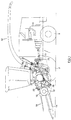
- FIG. 1 there is shown a forage harvester having a main frame 1 on which there are mounted ground engaging traction wheels 2 and steering wheels 3.
- the forage harvester is shown equipped with a crop collecting apparatus, in the form of a row crop attachment 10, suitable for the harvesting of maize, but which can be replaced with a conventional windrow pick-up device or a conventional cutter bar attachment, depending on the type of crop to be harvested.
- the row crop attachment 10 comprises an attachment frame 12, which supports a plurality of row crop units 14, operable to harvest maize stalks from the field and to convey the same rearwardly to an auger 16, which in turn delivers the crop material to the bite of feeder means installed in a front unit of the forage harvester.
- Said feeder means comprise lower feeder means, including a forward lower feedroll 26, and a smooth, rear lower feedroll 27, and upper feeder means, including an upper forward feedroll 20 and an upper rear feedroll 21.
- Said upper and lower feeder means rotate to convey the crop material inbetween to a cutterhead 36, which is mounted within a cutterhead frame 34 and comprises a plurality of knives 37, generating a cylindrical peripheral shape or profile, when the cutterhead 36 is rotated.
- the knives 37 cooperate with a fixed shearbar to cut the crop material to length and to project it to a blower rotor 40 which is installed within a blower housing 38.
- the blower rotor 40 comprises a plurality of paddles, which throw the material upwardly through the blower outlet into a discharge spout 42, which can be positioned by an operator to direct the cut crop material as required, normally into a wagon which is moving alongside or behind the forage harvester.
- the forage harvester is driven by a power plant or engine 44, which is drivingly connected to a power-take-off (PTO) gearbox 45.
- the output shaft of the PTO gearbox 45 is linked to a drive shaft 46, which is connected to an input shaft of the transmission 47.
- An output shaft of this transmission provides via a safety clutch 48 and a drive shaft 52 motive power to a lower feedroll transmission 54 on the left hand side of the front unit.
- This transmission 54 is connected directly to the lower feedrolls 26, 27 and through a drive shaft (not shown) to the upper feedroll transmission 56, drivingly interconnecting the upper feedrolls 21, 20.
- the front unit of the forage harvester is equipped with an apparatus 58 for detecting the presence of foreign bodies in the flow of crop material to the rotating cutterhead 36.
- This apparatus 58 may be installed inside the forward lower feedroll 26 as shown in Figure 1 or at any other convenient place along the path of the crop material to the cutterhead 36.
- the detecting apparatus 58 illustrated is a metal detector of the type described in European patent application 96.200.808.2.
- the drive arrest apparatus of the invention may equally be used with a hard object detector of the type described in US-A-4,353,199.
- the apparatus 58 Upon detection of a foreign object the apparatus 58 generates a signal to actuate a quick stop apparatus 60 which is mounted on the drive line to the feedrolls 20, 21, 26, 27.
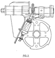
- the quick stop apparatus 60 comprises an electrical actuator, including a solenoid coil 62 which is affixed to a support plate 64 mounted on the transmission 47.
- a core member 66 is installed for sliding movement in the coil 62.
- the upper end of the core member 66 has a slot for receiving therein a horizontally extending finger 70.
- the upper edge of the finger 70 is engaged by a roller 68 which is rotatably connected to the core member 66.
- the finger 70 is affixed to a pawl 74 and can be pivoted in unison therewith about a pin 72 extending trough an extension of a collar 76, which is secured by a pin 78 to a cylindrical slide 80. Both ends of the slide 80 are received in bores 82, 84 of a support structure 86 attached to the support plate 64.
- An extension rod 88 is screwed in the right hand end of the slide 80 (left hand end as seen in Figure 2) for carrying a pair of elastomeric members 90 mounted between steel plates 92.
- the collar 76 is pulled against the support structure 86 by a pair of nuts 94 thereby simultaneously loading the elastomeric members 90.
- a ratchet wheel 50 is mounted onto the driving portion of the safety clutch 48, which is connected to the drive shaft 52.
- the pawl 74 and the finger 70 are forced upwardly and away from the ratchet wheel 50 by a torsion spring 96 which is mounted over the pivot pin 72.
- the finger 70 lifts the core member 66 of the actuator and holds it against a spring assembly 98 which is attached to the support structure 86.
- a computer means applies an electrical current to the solenoid 62, thereby generating an magnetic field which pulls the core member 66 inwardly.
- the finger 70 and the pawl 74 are pivoted towards the periphery of the ratchet wheel 50.
- the pawl 74 engages one of the ratchet teeth the wheel 50 and the driving portion of the safety clutch 48 are arrested immediately.
- the feedrolls 20, 21, 26, 27 are stopped by the drive shaft 52 which is also affixed to said driving portion.
- the safety clutch 48 disengages such that its driven portion may still rotate freely under action of the engine 44 and the transmission 47.
- the shock on the pawl 74 is absorbed by the elastomeric members 90 which are compressed by the movement of the collar 76 and the slide 80. During this movement the roller 68 travels over the edge of the finger 70 to hold the pawl 74 down against the force of the torsion spring 96 and to ensure constant engagement of the pawl tip with the periphery of the ratchet wheel 50.
- the metal detector apparatus 58 comprises a pair of coils 100 arranged around a set of permanent magnets. The presence of a metal object in the crop flow causes a variation in the magnetic field of these magnets, which induces an emf across the coils.
- Circuitry 102 as described in European patent application 96.200.808.2 is linked to the coils for capturing the voltage variations and generating a high output signal when a metal object is detected.
- This signal is fed to an opto-coupler device 104, comprising a LED and photo-sensitive transistor which is linked to an input pin PA2 of a micro-processor 106. Normally the input to this pin will be high. Detection of metal will trigger the transistor of the device 104 and short the input pin PA2 to ground.
- the opto-coupler device may be of the type ILQ1 provided by Siemens.
- the micro-processor 106 may be a 68HC11EX micro-processor of Motorola. It is linked by a data bus 108 and an address bus 110 to a RAM memory 112 and an erasable ROM memory 114.
- the RAM memory may be a conventional RAM memory such as the Motorola MB8464A.
- the erasable memory may be a flash EPROM memory such as the 29F010 supplied by AMD.
- the micro-processor 106 is operable to select addresses and chips through a latch means 116 and a chip selector 118.
- the latch means 116 may be CMOS buffer 74HC573 of Motorola and the chip selector a Gate Array Logic 16V8.
- the circuitry shown in Figure 3 can be used in a decentralized control system, wherein a plurality of micro-processors, interconnected by a high-speed network, control various settings of the harvester.
- the micro-processor 106 exchanges network data via the data bus 108 and a Controller Area Network (CAN) interface 120.
- CAN Controller Area Network
- the latter is linked by a transmitter-receiver unit 122 to CAN lines 124.
- the CAN network can be used to provide messages and warnings to the operator in the cab 43 or to monitor commands given by the same.
- the interface 120 may be a Philips interface PCA82C200P and the unit 122 may be a Philips transceiver PCA82C250.
- the micro-processor 106 Upon detection of a metal object by the metal detector apparatus 58, the micro-processor 106 generates at an output pin PA6 a high signal to an electronic switch means 126 for connecting a voltage source V 1 to the coil 62 of the quick stop apparatus 60.
- the switch means 126 is a smartfet, provided with diagnostic means, such as the Profet BTS432D of Siemens. It has a status pin ST which is high during normal actuation of the coil 62, but which is low under abnormal load, such as caused by a short circuit to ground or by a broken electrical lead.
- the output of the status pin ST may be fed directly to an input pin of the microprocessor 106 or, as illustrated in Figure 3, via a digital gate chip 128 and a serial network, comprising lines 130, to input pins PD0, PD1 of the same micro-processor 106.
- This serial network may be a I 2 C network and the chip 128 may be of the type PCF8574 manufactured by Philips.
- the circuitry further comprises means for sensing the negative pulse which is generated by the coil 62 when the switch means 126 cuts the electrical current to the coil.
- the sensing means comprise a connection between the coil and ground, provided with a diode 132 and an opto-coupler 134.
- the light-emitting diode 135 of the opto-coupler connects the diode 32 to ground and directs a light pulse to its transistor 136 when a negative voltage pulse is induced in the coil 62 and current is flowing from ground through the diodes 135, 132 to the coil.
- the collector of transistor 136 is via a load resistor to voltage source V 2 .
- the collector is directly linked to an input pin PA1 of the micro-processor 106.
- the micro-processor will sense a high input, but when the switch means 126 interrupts the current supply to the coil 62, the pulse through the opto-coupler 134 will connect the input pin PA1 to ground. The use of this optical connection prevents that substantial electrical pulses generated by the coil are transmitted to the remainder of the circuitry, where they might wreck the electronic components.
- the operation of the drive arresting apparatus is controlled by a pawl routine as set forth in the attached Appendix 1.
- This routine is stored into the ROM memory 114 and is fetched by the micro-processor 106.
- the pawl routine is executed on an interrupt basis every 50 msec.
- the computer means first checks the status of the flag pawl_puls_on, which is set by an interrupt routine upon actual detection of metal by the apparatus 58.
- the electrical actuator may only be activated for a short period which may be in the order of 0.5 sec, which on the one hand suffices for realizing a positive stop of the feedrolls 20, 21, 26, 27 and on the other precludes damages caused by over-heating of the coil 62. If the flag pawl_puls_on is set and the pawl activation period has not expired yet, the routine fetches from the I 2 C network 130 the value of IN_PAWL_L2, representing the status of the switch means 126, to see whether any anomalies in the circuitry have arisen.
- the pawl routine resets the output pin PA6 for temporarily interrupting the current to the coil 62. Thereafter the switch 126 is activated again to resume the actuation of the stop apparatus 60.
- the routine loads a CAN message indicative of the pawl action into the CAN lines 124 for generating a warning to the operator and automatically disengaging a portion of the drive line to the feedrolls 20, 21, 26, 27. Then a pawl hold timer is incremented.
- the output pin PA6 is reset to cut the current to the coil 62 and release the pawl 74.
- the pawl routine In case that no foreign object has been detected or that the pawl activation period has expired the pawl routine immediately proceeds to a test routine which first resets the pin PA6 and the pawl hold timer. A flag metal_detector is checked to see whether the metal detecting apparatus 58 is operative. In case it is not, the pawl test timer is set to a value indicating the expiration of a interval of 5 sec between two consecutive pawl tests, such that the operability of the system may be tested immediately after the detecting apparatus 58 has been switched on.
- the routine checks the value of the test timer to see whether the 5 sec interval between consecutive pawl tests has expired already. In case this interval has not expired yet, the test timer is incremented and the routine is terminated.
- the routine Upon expiration of the interval the routine proceeds to an actual pawl test, wherein the pawl mechanism is activated during a test time of 4 msec. This period is not long enough to achieve a proper motion of the core member 66 into the coil 62, but it suffices to assess the condition of the circuitry controlling the current to the coil.
- test timer is reset and the pin PA6 of the micro-processor is set to actuate the switch means 126. Then 750 clock pulses are counted for providing a time delay of 1.5 msec, necessary for the switch means 126 and the circuitry to the coil 62 to stabilize. Thereafter a pawl failure flag is set and the interrupt routine, which might otherwise interfere with the output settings of the micro-processor 106 is disabled.
- the test routine then fetches for three consecutive times the value of the status pin of the switch means 126 from the serial network. If during at least one of these three checks the fetched value is low, corresponding to a high output of the status pin, the pawl failure flag is reset. In case the value remains high during the three checks, as a result of a failure such as an open circuit or a short to ground, the failure flag remains set. Thereafter the interrupt routine is enabled again.
- Each loading and checking of the status value took about 0.5 msec, such that the total interval during which the pawl mechanism was actuated, amounts to about 4 msec.
- An intermediate detection of a foreign object by the apparatus 58 may have set the flag pawl_puls_on during the foregoing test procedure.
- the pawl routine checks this flag and disables the switch means 126 only in case this flag is low. Otherwise the coil 62 remains activated at the end of the pawl routine.
- the pawl failure flag is checked in another routine which is not described herein in further detail for generating an error message to the operator in the cab 43.
- the pawl routine then resets the test timer and sets the pin PA6 gate of the micro-processor 106 to actuate the switch means 126. Then the computer means count 2000 clock pulses for providing a coil actuation interval of 4 msec. Thereafter the flag pawl_puls_on is checked to see whether the metal detecting apparatus 58 has detected a foreign body in the crop flow. In case it has, the coil remains actuated to pull the pawl 74 against the ratchet wheel 50 and to stop the feedrolls 20, 21, 26, 27.
- the switch means 126 is disabled to cut the current to the coil 62.
- the flag pawl_puls_on is checked once more and the switch means 126 is actuated again in case this second check reveals an intermediate metal detection.
- the routine proceeds from the solenoid break to the step in which the pawl failure flag is set. Then the input pin PA6 is checked for three consecutive times. When no deficiencies have occurred in the coil circuit, the interruption of the current to the coil 62 will generate a negative emf pulse at its connection to the switch means 126 and a short current will flow from ground through the opto-coupler 134 to the coil 62.
- the pawl routine checks the input pin PA1, which is linked to the opto-coupler, for three times for verifying whether any voltage pulse has occurred. In case at least one of these checks reveals that such pulse has been generated, the pawl failure flag is reset and the pawl routine is terminated. When the input to the pin PA1 remains high during these checks, also the pawl failure flag remains high at the end of the routine.
- This flag may be checked in another routine for generating an error message to the operator in the cab 43. Thus may be detected a possible coil circuit failure, such as a short circuit or a broken coil 62.
- the metal detecting apparatus 58 may replace with another type of foreign object detector, such as a stone detector. It is also conceivable to install the present quick stop apparatus in other types of crop processing machinery such as those comprising crop compressing rolls.
- the quick stop apparatus 60 may be installed on another portion of the drive line of the feeder means to cause immediate arrest of only one or two of the feedrolls.
Landscapes
- Life Sciences & Earth Sciences (AREA)
- Environmental Sciences (AREA)
- Safety Devices And Accessories For Harvesting Machines (AREA)
Applications Claiming Priority (2)
| Application Number | Priority Date | Filing Date | Title |
|---|---|---|---|
| GB9615969 | 1996-07-30 | ||
| GB9615969A GB2315657A (en) | 1996-07-30 | 1996-07-30 | Harvesting machines,protective arrangements |
Publications (3)
| Publication Number | Publication Date |
|---|---|
| EP0821871A2 true EP0821871A2 (fr) | 1998-02-04 |
| EP0821871A3 EP0821871A3 (fr) | 1999-12-01 |
| EP0821871B1 EP0821871B1 (fr) | 2002-04-03 |
Family
ID=10797733
Family Applications (1)
| Application Number | Title | Priority Date | Filing Date |
|---|---|---|---|
| EP97202235A Expired - Lifetime EP0821871B1 (fr) | 1996-07-30 | 1997-07-17 | Dispositif d'arrêt d'alimentation dans une machine de récolte |
Country Status (4)
| Country | Link |
|---|---|
| US (1) | US5921071A (fr) |
| EP (1) | EP0821871B1 (fr) |
| DE (1) | DE69711509T2 (fr) |
| GB (1) | GB2315657A (fr) |
Cited By (4)
| Publication number | Priority date | Publication date | Assignee | Title |
|---|---|---|---|---|
| EP1101398A1 (fr) * | 1999-11-20 | 2001-05-23 | Deere & Company | Dispositif d'arrêt pour l'arrangement de transport de produit de récolte |
| EP1126485A3 (fr) * | 2000-02-17 | 2003-06-18 | Deere & Company | Circuit de commutation pour un arrêt instantané |
| EP2040096A1 (fr) | 2006-05-30 | 2009-03-25 | CNH Belgium N.V. | Système de détection d'objets étrangers pour moissonneuses agricoles |
| CN109699321A (zh) * | 2019-03-13 | 2019-05-03 | 农业农村部南京农业机械化研究所 | 切割秸秆试验台 |
Families Citing this family (18)
| Publication number | Priority date | Publication date | Assignee | Title |
|---|---|---|---|---|
| DE19854562A1 (de) | 1998-11-26 | 2000-05-31 | Claas Saulgau Gmbh | Einrichtung zur Überwachung der Einzugsbaugruppe einer landwirtschaftlichen Erntemaschine |
| DE19903471C1 (de) * | 1999-01-29 | 2000-06-08 | Deere & Co | Erntemaschine mit Durchsatzmeßvorrichtung |
| DE19904626C2 (de) * | 1999-02-05 | 2001-05-17 | Case Harvesting Sys Gmbh | Verfahren zum Erkennen von Fremdkörpern in Erntemaschinen |
| DE19918552A1 (de) * | 1999-04-23 | 2000-10-26 | Deere & Co | Erntemaschine |
| GB0005178D0 (en) | 2000-03-06 | 2000-04-26 | Ford New Holland Nv | Feeder controls for a forage harvester |
| US6584755B2 (en) * | 2001-08-14 | 2003-07-01 | Deere & Company | Apparatus for adjusting the spacing and/or the contact pressure between two rollers of a kernel processor |
| DE10145407C2 (de) * | 2001-09-14 | 2003-11-13 | Walterscheid Gmbh Gkn | Antriebsanordnung und Verfahren zum Festsetzen mindestens eines Arbeitsaggregats |
| US6955310B1 (en) * | 2002-05-21 | 2005-10-18 | Tramor, Inc. | Remote control assembly for wood chipper |
| DE102006019243A1 (de) * | 2006-04-21 | 2007-11-08 | Claas Selbstfahrende Erntemaschinen Gmbh | Verfahren und Vorrichtung zur Einstellung der Schnittlänge einer Häckseleinrichtung einer landwirtschaftlichen Erntemaschine |
| DE102007025310A1 (de) * | 2007-05-30 | 2008-12-04 | Claas Selbstfahrende Erntemaschinen Gmbh | Landwirtschaftliche Erntemaschine mit einer Fremdkörpererkennungsvorrichtung |
| US7947943B2 (en) * | 2007-06-08 | 2011-05-24 | Disney Enterprises, Inc. | Pawl and ratchet assembly adapted for indirect sensing of proper operation |
| DE102011007843A1 (de) * | 2011-04-21 | 2012-10-25 | Deere & Company | Einrichtung zum Nachweis eines in eine Erntemaschine eingedrungenen Fremdkörpers |
| ITBO20110716A1 (it) * | 2011-12-15 | 2013-06-16 | Gallignani Spa | Dispositivo di sicurezza per macchine agricole, e relativa macchina agricola |
| US8740115B1 (en) * | 2012-04-23 | 2014-06-03 | Samelin Innovations, LLC | Sink disposal and metal sensor |
| US9194113B1 (en) | 2012-04-23 | 2015-11-24 | Samelin Innovations, LLC | Sink disposal and metal sensor |
| DE102012107227B4 (de) * | 2012-08-07 | 2022-07-14 | Linde Hydraulics Gmbh & Co. Kg | Antriebssystem zum Antrieb einer Häcksel- und Einzugsvorrichtung einer Erntemaschine |
| US10286404B2 (en) | 2014-08-11 | 2019-05-14 | Samelin Innovations, LLC | Detecting unintended objects in under-sink disposal |
| DE102024108696A1 (de) * | 2024-03-27 | 2025-10-02 | Claas Selbstfahrende Erntemaschinen Gmbh | Landwirtschaftliche Erntemaschine |
Family Cites Families (15)
| Publication number | Priority date | Publication date | Assignee | Title |
|---|---|---|---|---|
| GB1225611A (fr) * | 1967-09-15 | 1971-03-17 | ||
| US3629816A (en) * | 1970-08-10 | 1971-12-21 | Gen Motors Corp | Air cushion actuation and monitoring circuit |
| FR2410429B1 (fr) * | 1977-12-02 | 1985-06-28 | Sperry Nv | Moissonneuse de recolte |
| US4343137A (en) * | 1980-08-25 | 1982-08-10 | Sperry Corporation | Crop elevator decelerating means |
| US4296591A (en) * | 1980-10-01 | 1981-10-27 | Sperry Corporation | Damped apparatus for quick-stopping rotating members |
| US4353199A (en) * | 1981-04-15 | 1982-10-12 | Sperry Corporation | Stone detector for harvesting machines |
| US4433528A (en) * | 1982-08-30 | 1984-02-28 | Sperry Corporation | Metal detector apparatus |
| US4496105A (en) * | 1982-11-15 | 1985-01-29 | Gehl Company | Forage harvester drive and electric control therefor |
| US4531118A (en) * | 1983-08-29 | 1985-07-23 | Dickey-John Corporation | Metal detector |
| SU1250767A1 (ru) * | 1985-01-07 | 1986-08-15 | Центральный Научно-Исследовательский Институт Механизации И Электрификации Сельского Хозяйства Нечерноземной Зоны Ссср | Способ экстренной остановки ведомого вала рабочих органов машины и устройство дл его осуществлени |
| DE3532000A1 (de) * | 1985-09-07 | 1987-03-19 | Claas Saulgau Gmbh | Verfahren und einrichtung zum schnellstopp der einzugwalzen von feldhaeckslern |
| US4771755A (en) * | 1986-01-22 | 1988-09-20 | Honda Giken Kogyo K.K. | Abnormality detecting method for air-fuel ratio control system for internal combustion engines |
| US4843767A (en) * | 1988-03-28 | 1989-07-04 | Deere & Company | Automatic forage harvester knife sharpening system |
| JPS63289467A (ja) * | 1988-03-29 | 1988-11-25 | Mitsubishi Agricult Mach Co Ltd | 農機における自動制御装置の故障診断装置 |
| US5627475A (en) * | 1995-03-31 | 1997-05-06 | New Holland North America, Inc. | Metal detector coil resistance testing |
-
1996
- 1996-07-30 GB GB9615969A patent/GB2315657A/en not_active Withdrawn
-
1997
- 1997-07-17 EP EP97202235A patent/EP0821871B1/fr not_active Expired - Lifetime
- 1997-07-17 DE DE69711509T patent/DE69711509T2/de not_active Expired - Lifetime
- 1997-07-25 US US08/900,589 patent/US5921071A/en not_active Expired - Lifetime
Cited By (6)
| Publication number | Priority date | Publication date | Assignee | Title |
|---|---|---|---|---|
| EP1101398A1 (fr) * | 1999-11-20 | 2001-05-23 | Deere & Company | Dispositif d'arrêt pour l'arrangement de transport de produit de récolte |
| US6397570B1 (en) | 1999-11-20 | 2002-06-04 | Deere & Company | Stopping device for a crop transport mechanism |
| EP1126485A3 (fr) * | 2000-02-17 | 2003-06-18 | Deere & Company | Circuit de commutation pour un arrêt instantané |
| EP2040096A1 (fr) | 2006-05-30 | 2009-03-25 | CNH Belgium N.V. | Système de détection d'objets étrangers pour moissonneuses agricoles |
| CN109699321A (zh) * | 2019-03-13 | 2019-05-03 | 农业农村部南京农业机械化研究所 | 切割秸秆试验台 |
| CN109699321B (zh) * | 2019-03-13 | 2020-11-20 | 农业农村部南京农业机械化研究所 | 切割秸秆试验台 |
Also Published As
| Publication number | Publication date |
|---|---|
| GB9615969D0 (en) | 1996-09-11 |
| DE69711509D1 (de) | 2002-05-08 |
| DE69711509T2 (de) | 2009-09-24 |
| EP0821871B1 (fr) | 2002-04-03 |
| EP0821871A3 (fr) | 1999-12-01 |
| GB2315657A (en) | 1998-02-11 |
| US5921071A (en) | 1999-07-13 |
Similar Documents
| Publication | Publication Date | Title |
|---|---|---|
| EP0821871B1 (fr) | Dispositif d'arrêt d'alimentation dans une machine de récolte | |
| US4496105A (en) | Forage harvester drive and electric control therefor | |
| US6318056B1 (en) | Device for monitoring the intake subassembly of an agricultural harvesting machine | |
| US6397570B1 (en) | Stopping device for a crop transport mechanism | |
| US3959953A (en) | Apparatus to detect the passage of ferrous material in crop harvesting machines | |
| EP4533936A2 (fr) | Commande autonome d'une tête de récolte de culture | |
| US8733242B2 (en) | Combination agricultural apparatus and towing vehicle with a safety feature | |
| US6381932B1 (en) | Harvesting machine | |
| US9795081B2 (en) | Method for operating a combine harvester with belt drive configured to implement a measure to prevent slip of the belt drive and communicate the measure to an operator | |
| US4261161A (en) | Agricultural machinery protective system | |
| US20030115846A1 (en) | Inertial system for detecting foreign objects between contra-rotating rolls | |
| WO2023180563A1 (fr) | Presse à balles comprenant une combinaison de noueurs et d'aiguilles | |
| BE1023141B1 (nl) | Knopenleggersysteem voor landbouwbalenpers | |
| US5704199A (en) | Method for moving a shearbar in a forage harvester | |
| US20240292780A1 (en) | System to adjust the phasing of chopper blades for a sugarcane harvester | |
| US6690285B2 (en) | Agricultural implement component rotation alarm | |
| US20230360404A1 (en) | Detection of corn head row unit slip clutch disengagement using perception system | |
| GB2035029A (en) | Crop harvesting machines | |
| AU2017101791B4 (en) | Process Condition Monitoring Apparatus | |
| US20060010845A1 (en) | Harvester control | |
| EP1387230A1 (fr) | Dispositif pour signale un danger sur une machine agricole | |
| DE102014109688B4 (de) | Verfahren und Steuerungseinrichtung zum Betreiben einer Erntemaschine | |
| JP7735154B2 (ja) | コンバイン | |
| US20240349650A1 (en) | Method of controlling a drive system of a grass pickup header | |
| US10459023B2 (en) | System and method to determine stress levels in harvesting machine circuits |
Legal Events
| Date | Code | Title | Description |
|---|---|---|---|
| PUAI | Public reference made under article 153(3) epc to a published international application that has entered the european phase |
Free format text: ORIGINAL CODE: 0009012 |
|
| AK | Designated contracting states |
Kind code of ref document: A2 Designated state(s): DE FR GB IT |
|
| AX | Request for extension of the european patent |
Free format text: AL;LT;LV;RO;SI |
|
| PUAL | Search report despatched |
Free format text: ORIGINAL CODE: 0009013 |
|
| AK | Designated contracting states |
Kind code of ref document: A3 Designated state(s): AT BE CH DE DK ES FI FR GB GR IE IT LI LU MC NL PT SE |
|
| AX | Request for extension of the european patent |
Free format text: AL;LT;LV;RO;SI |
|
| RIC1 | Information provided on ipc code assigned before grant |
Free format text: 6A 01F 29/16 A, 6A 01D 75/18 B |
|
| 17P | Request for examination filed |
Effective date: 20000517 |
|
| AKX | Designation fees paid |
Free format text: DE FR GB IT |
|
| GRAG | Despatch of communication of intention to grant |
Free format text: ORIGINAL CODE: EPIDOS AGRA |
|
| 17Q | First examination report despatched |
Effective date: 20010420 |
|
| GRAG | Despatch of communication of intention to grant |
Free format text: ORIGINAL CODE: EPIDOS AGRA |
|
| GRAG | Despatch of communication of intention to grant |
Free format text: ORIGINAL CODE: EPIDOS AGRA |
|
| GRAH | Despatch of communication of intention to grant a patent |
Free format text: ORIGINAL CODE: EPIDOS IGRA |
|
| REG | Reference to a national code |
Ref country code: GB Ref legal event code: IF02 |
|
| GRAH | Despatch of communication of intention to grant a patent |
Free format text: ORIGINAL CODE: EPIDOS IGRA |
|
| GRAA | (expected) grant |
Free format text: ORIGINAL CODE: 0009210 |
|
| AK | Designated contracting states |
Kind code of ref document: B1 Designated state(s): DE FR GB IT |
|
| PG25 | Lapsed in a contracting state [announced via postgrant information from national office to epo] |
Ref country code: IT Free format text: LAPSE BECAUSE OF FAILURE TO SUBMIT A TRANSLATION OF THE DESCRIPTION OR TO PAY THE FEE WITHIN THE PRESCRIBED TIME-LIMIT;WARNING: LAPSES OF ITALIAN PATENTS WITH EFFECTIVE DATE BEFORE 2007 MAY HAVE OCCURRED AT ANY TIME BEFORE 2007. THE CORRECT EFFECTIVE DATE MAY BE DIFFERENT FROM THE ONE RECORDED. Effective date: 20020403 |
|
| REF | Corresponds to: |
Ref document number: 69711509 Country of ref document: DE Date of ref document: 20020508 |
|
| ET | Fr: translation filed | ||
| PLBE | No opposition filed within time limit |
Free format text: ORIGINAL CODE: 0009261 |
|
| STAA | Information on the status of an ep patent application or granted ep patent |
Free format text: STATUS: NO OPPOSITION FILED WITHIN TIME LIMIT |
|
| 26N | No opposition filed |
Effective date: 20030106 |
|
| REG | Reference to a national code |
Ref country code: FR Ref legal event code: CD |
|
| REG | Reference to a national code |
Ref country code: GB Ref legal event code: 746 Effective date: 20090114 |
|
| PGFP | Annual fee paid to national office [announced via postgrant information from national office to epo] |
Ref country code: GB Payment date: 20120709 Year of fee payment: 16 |
|
| PGFP | Annual fee paid to national office [announced via postgrant information from national office to epo] |
Ref country code: FR Payment date: 20120731 Year of fee payment: 16 Ref country code: DE Payment date: 20120710 Year of fee payment: 16 |
|
| GBPC | Gb: european patent ceased through non-payment of renewal fee |
Effective date: 20130717 |
|
| REG | Reference to a national code |
Ref country code: FR Ref legal event code: ST Effective date: 20140331 |
|
| PG25 | Lapsed in a contracting state [announced via postgrant information from national office to epo] |
Ref country code: DE Free format text: LAPSE BECAUSE OF NON-PAYMENT OF DUE FEES Effective date: 20140201 Ref country code: GB Free format text: LAPSE BECAUSE OF NON-PAYMENT OF DUE FEES Effective date: 20130717 |
|
| REG | Reference to a national code |
Ref country code: DE Ref legal event code: R119 Ref document number: 69711509 Country of ref document: DE Effective date: 20140201 |
|
| PG25 | Lapsed in a contracting state [announced via postgrant information from national office to epo] |
Ref country code: FR Free format text: LAPSE BECAUSE OF NON-PAYMENT OF DUE FEES Effective date: 20130731 |