EP0822009A1 - Vorrichtung zum Auftragen eines nicht-festen Produkts - Google Patents
Vorrichtung zum Auftragen eines nicht-festen Produkts Download PDFInfo
- Publication number
- EP0822009A1 EP0822009A1 EP97401642A EP97401642A EP0822009A1 EP 0822009 A1 EP0822009 A1 EP 0822009A1 EP 97401642 A EP97401642 A EP 97401642A EP 97401642 A EP97401642 A EP 97401642A EP 0822009 A1 EP0822009 A1 EP 0822009A1
- Authority
- EP
- European Patent Office
- Prior art keywords
- return
- handle
- nut
- rod
- piston
- Prior art date
- Legal status (The legal status is an assumption and is not a legal conclusion. Google has not performed a legal analysis and makes no representation as to the accuracy of the status listed.)
- Granted
Links
- 239000012265 solid product Substances 0.000 title claims description 5
- 238000005452 bending Methods 0.000 claims abstract description 5
- 239000000047 product Substances 0.000 claims description 16
- 230000003213 activating effect Effects 0.000 abstract 1
- 230000002093 peripheral effect Effects 0.000 abstract 1
- 230000007246 mechanism Effects 0.000 description 9
- 230000000903 blocking effect Effects 0.000 description 4
- 238000005086 pumping Methods 0.000 description 4
- 230000001174 ascending effect Effects 0.000 description 3
- 239000000203 mixture Substances 0.000 description 3
- 238000006073 displacement reaction Methods 0.000 description 2
- 239000007787 solid Substances 0.000 description 2
- 238000009413 insulation Methods 0.000 description 1
- 230000007257 malfunction Effects 0.000 description 1
- 229920005989 resin Polymers 0.000 description 1
- 239000011347 resin Substances 0.000 description 1
- 230000000284 resting effect Effects 0.000 description 1
- 239000000565 sealant Substances 0.000 description 1
Images

Classifications
-
- B—PERFORMING OPERATIONS; TRANSPORTING
- B05—SPRAYING OR ATOMISING IN GENERAL; APPLYING FLUENT MATERIALS TO SURFACES, IN GENERAL
- B05C—APPARATUS FOR APPLYING FLUENT MATERIALS TO SURFACES, IN GENERAL
- B05C17/00—Hand tools or apparatus using hand held tools, for applying liquids or other fluent materials to, for spreading applied liquids or other fluent materials on, or for partially removing applied liquids or other fluent materials from, surfaces
- B05C17/005—Hand tools or apparatus using hand held tools, for applying liquids or other fluent materials to, for spreading applied liquids or other fluent materials on, or for partially removing applied liquids or other fluent materials from, surfaces for discharging material from a reservoir or container located in or on the hand tool through an outlet orifice by pressure without using surface contacting members like pads or brushes
- B05C17/01—Hand tools or apparatus using hand held tools, for applying liquids or other fluent materials to, for spreading applied liquids or other fluent materials on, or for partially removing applied liquids or other fluent materials from, surfaces for discharging material from a reservoir or container located in or on the hand tool through an outlet orifice by pressure without using surface contacting members like pads or brushes with manually mechanically or electrically actuated piston or the like
- B05C17/0103—Hand tools or apparatus using hand held tools, for applying liquids or other fluent materials to, for spreading applied liquids or other fluent materials on, or for partially removing applied liquids or other fluent materials from, surfaces for discharging material from a reservoir or container located in or on the hand tool through an outlet orifice by pressure without using surface contacting members like pads or brushes with manually mechanically or electrically actuated piston or the like with electrically actuated piston or the like
Definitions
- the present invention relates to an apparatus for applying a non-solid, in particular viscous, product from a cartridge storage device mounted on the device.
- a cartridge may include an outer casing with, on one side, a nozzle intended to receive an application nozzle, and on the other side, a bottom wall intended to slide towards the end piece and push the product out of the nozzle and nozzle.
- Such devices, or guns are generally used to apply resins or sealants for thermal and / or sound insulation.
- the bottom wall of a cartridge is intended to slide under the action of the advance of a piston actuated manually by means of a pumping handle by means of a rack mechanism or by advance by friction.
- the nut in advance is intended to come and engage on the rod of piston tilting on the rod, under the action of a pumping of the handle, in order to drive the piston forward along an advance elementary, and to disengage after pumping, the non-return nut, already engaged on the rod, blocking the piston to prevent it from back off.
- the application of a determined quantity of the cartridge product requires a certain advance of the piston resulting from a plurality of successive pumping.
- the present invention provides a new apparatus for applying non-solid product, first aimed at reducing the physical effort of operator for product application.
- the invention relates to an apparatus for applying a non-solid product comprising means for receiving at least a product storage cartridge, with a rear thrust wall of the product, a push piston, means for driving the piston and a handle for controlling the drive means, characterized by the fact that the drive means are arranged to cause any application of the product by a single actuation of the control handle and include a intermediate feed rod arranged to be driven by a reciprocating back and forth and driving the piston pushed forward during the forward movement.
- the operator only has to press once the handle and maintain its action to pump and apply the product.
- means are provided to stop the engine only at the end of the return movement of the intermediate link.
- the advance link comprises a zone of flexion arranged to actuate a stop switch exceptional engine, by bending.
- a non-return rear nut cooperating by friction with the thrust piston, it is provided an intermediate non-return link between the handle order and the non-return nut.
- the non-return link is pivotally mounted at the front on an axis integral with the handle control and, at the rear, on the side of the mounted check nut mobile, with two degrees of freedom, around a guide axis back.
- the rear guide axis of the non-return link, its axis pivot on the handle and the axis of rotation of the handle are arranged to be aligned when the handle is actuated.
- the force exerted backwards on the thrust piston no longer applies to the handle itself, i.e. the hand of the operator, but on its axis of rotation integral with the housing the device.
- the non-return link includes a light rear, extended by a groove in which is received the axis of rear guide, and through which the non-return nut extends.
- the rear light of the non-return link and the nut non-return valves are arranged so that when the handle is not actuated, the cooperation of the non-return nut and the piston of thrust is broken.
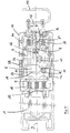
- the preferred embodiment of the apparatus which will now be described can receive two storage cartridges containing respectively two products, not solid to be mixed before their application.
- the two pistons 2 are mutually parallel and symmetrical by relative to a longitudinal axis 9 of symmetry of the mechanisms drive and anti-return.
- Each front nut 5 is in abutment, on one side, against the front end of the feed rod 6 under the action of a return spring 13 described below and, on the opposite side, against a rear stop 14 secured to the housing 10, under the action of a nut spring before 15 surrounding the piston 2 at the front of the front nut 5 and fixed in position at its front end in the housing 10.
- the push pistons 2 can slide through the front nuts 5 intended to tilt slightly, towards their respective pistons, from their position rest perpendicular to axis 9 to a locked position inclined for which the relative sliding of the nuts before 5 and of their respective pistons 2 are blocked.
- the return spring 13 of the feed rod 6, extending along axis 9, is held in the housing 10 by its front end and resting against the front of the rod 6 by its rear end, by through the nuts before 5.
- the non-return mechanism includes two rear non-return nuts 21, mounted like the front nuts 5 but on the rear parts of the two respective pistons 2, and intended to prevent the recoil of push pistons 2 between two elementary advances thereof, as will be explained in the description of the operation of the device.
- each rear nut 21 In the rest position of the applicator, each rear nut 21 abuts against a ring 26 mounted around the piston 2 at the rear of the rear nut 21, under the action of a nut spring rear 27 fixed to the housing 10 and surrounding the piston 2 at the front of the rear nuts 21.
- the rear nuts 21 extend in a common plane substantially perpendicular to axis 9 and can pivot towards their respective pistons between a rest position perpendicular to the axis piston and a locking position inclined relative to this axis and reached by actuation of non-return links described more far.
- the pistons 2 In the rear nut rest position 21, the pistons 2 can slide through their rear nuts 21, and in the locked position, the pistons 2 are blocked in translation backwards by the nuts rear 21.
- P 2 be the plane of FIG. 1, containing the axes of the pistons 2.
- the two intermediate non-return links 22, for actuating the two rear nuts 21 respectively, extend in the vicinity of their respective pistons 2, in two lateral planes P1 perpendicular to the plane P2.
- the rear part of each link 22 provides a light 25 through which the rear nut 21 of the neighboring piston 2 extends.
- the non-return links 22 are mounted, at the front, pivoting respectively around two pivot axes 23 integral with the control handle 4 and, at the rear, movable with two degrees of freedom (in translation parallel to axis 9 and in pivoting) respectively around two guide axes 24 integral with the housing 10.
- the control handle 4 is pivotally mounted around an axis of rotation 28 integral with the housing 10, and maintained in the rest position by return springs 29 fixed to the housing 10.
- the guide axes 24 and rotation axes 28 extend in the plane P2.
- the pivot axes 23 are movable between a rest position and an operating position reached by actuation of the handle 4. In the rest position, the pivot axis 23 of each rear nuts 21 is outside the plane P2, on the side not containing not the control handle 4, and, in the operating position, contained in the plane P2, the pivot axes 23 and guide axes 24 of each non-return link 22 and the axis of rotation 28 of the handle 4 then being aligned in the plane P1 of extension of this link 22.
- the application apparatus further comprises a switch 11 for starting of the motor 3 located in the vicinity of the axis 9 and the control handle 4, a switch 16 for final stop of the engine 3 carried by the feed rod 6, adjacent to the thrust roller 8, and a exceptional stop switch 17 of the motor 3 disposed at the interior of a slot 18 formed in the front part of the link in advance 6.
- the slot 18 has two interior faces 19 opposite one of the other, perpendicular to axis 9, and connected to each other by a single side constituting a bending zone 20 provided so that the two faces 19 can be folded towards each other and actuate the exceptional stop switch 17.
- a forcing pin 12 secured to the feed rod 6 is disposed in the rear vicinity of cam 7, in order to force the return of the rod 6 under the action of cam 7 in downward phase, as this will be explained later.
- the applicator finally has a rear handle 30 manual drive to the rear of the push pistons 2, mounted on the rear ends of the pistons 2.
- control handle 4 In order to apply a desired amount of the product mixture contained in the storage cartridges, received in their housing 1, the control handle 4 is actuated by rotating it, here backwards, around its axis of rotation 28.
- the pivoting of the control handle 4 causes the pivoting and the advance of the two non-return links 22, against the action of return springs 29, until the pivot axes are aligned 23, rotation 28 and guide 24.
- the displacement resulting from that of the lights 25 rotates and slightly advances the non-return nuts rear 21 to their locked position, the pistons 2 do not then being able to move back further.
- the control handle 4 actuates the switch 11 for starting the motor 3.
- the motor 3, in walking, drives the rotary cam 7 which, during a phase ascending, push forward the intermediate feed rod 6, in a forward movement, via the thrust roller 8 turning and advancing along axis 9 simultaneously, advancing the rod 6 acting against the action of the return spring 13.
- cam 7 begins a downward phase during which it stops driving the feed rod 6 forward.
- cam 7 After the downward phase, cam 7 begins a new phase ascending causing a new elementary advance of push pistons 2.
- the cam 7 in the downward phase drives towards rear the forcing pin 12 by forcing the retraction of the rod in advance 6.
- the drive means include a single nut before training, by friction, of each push piston.
- a plurality of nuts before driving each piston of thrust mounted side by side on the piston could also be provided to increase the friction surface between the nuts front and the piston.
Landscapes
- Mechanical Engineering (AREA)
- Engineering & Computer Science (AREA)
- Coating Apparatus (AREA)
- Ropes Or Cables (AREA)
- Reciprocating Pumps (AREA)
- Glass Compositions (AREA)
- Seal Device For Vehicle (AREA)
- Processes Of Treating Macromolecular Substances (AREA)
- Saccharide Compounds (AREA)
- Vending Machines For Individual Products (AREA)
- Transmission Devices (AREA)
- De-Stacking Of Articles (AREA)
- Inorganic Insulating Materials (AREA)
- Ceramic Capacitors (AREA)
- General Preparation And Processing Of Foods (AREA)
- Detergent Compositions (AREA)
Applications Claiming Priority (2)
| Application Number | Priority Date | Filing Date | Title |
|---|---|---|---|
| FR9609564 | 1996-07-30 | ||
| FR9609564A FR2751898B1 (fr) | 1996-07-30 | 1996-07-30 | Appareil d'application d'un produit non solide |
Publications (2)
| Publication Number | Publication Date |
|---|---|
| EP0822009A1 true EP0822009A1 (de) | 1998-02-04 |
| EP0822009B1 EP0822009B1 (de) | 2002-10-02 |
Family
ID=9494619
Family Applications (1)
| Application Number | Title | Priority Date | Filing Date |
|---|---|---|---|
| EP97401642A Expired - Lifetime EP0822009B1 (de) | 1996-07-30 | 1997-07-09 | Vorrichtung zum Auftragen eines nicht-festen Produkts |
Country Status (11)
| Country | Link |
|---|---|
| US (1) | US5941423A (de) |
| EP (1) | EP0822009B1 (de) |
| JP (1) | JPH1066925A (de) |
| AT (1) | ATE225212T1 (de) |
| AU (1) | AU699815B2 (de) |
| DE (1) | DE69715991T2 (de) |
| FR (1) | FR2751898B1 (de) |
| MX (1) | MX9705563A (de) |
| NO (1) | NO973485L (de) |
| NZ (1) | NZ328334A (de) |
| SG (1) | SG55340A1 (de) |
Cited By (2)
| Publication number | Priority date | Publication date | Assignee | Title |
|---|---|---|---|---|
| EP1531011A1 (de) | 2003-11-13 | 2005-05-18 | Mixpac Systems AG | Elektrisch betriebenes Kartuschenaustraggerät |
| CN106513202A (zh) * | 2016-12-19 | 2017-03-22 | 北京京华派克聚合机械设备有限公司 | 喷涂装置 |
Families Citing this family (3)
| Publication number | Priority date | Publication date | Assignee | Title |
|---|---|---|---|---|
| CA2662331A1 (en) * | 2009-04-09 | 2010-10-09 | Duoject Medical Systems Inc. | Transfer device |
| DE102010030841A1 (de) * | 2010-07-02 | 2012-01-05 | Hilti Aktiengesellschaft | Auspressvorrichtung |
| CN107401668A (zh) * | 2016-05-19 | 2017-11-28 | 捷利科技股份有限公司 | 黄油枪的驱动装置 |
Citations (5)
| Publication number | Priority date | Publication date | Assignee | Title |
|---|---|---|---|---|
| US4249677A (en) * | 1979-04-03 | 1981-02-10 | Davis George B Jr | Hand held electric caulking gun |
| US4681524A (en) * | 1984-09-08 | 1987-07-21 | Cemedine Co., Ltd. | Extrusion device |
| US4840294A (en) | 1988-02-12 | 1989-06-20 | Illinois Tool Works Inc. | Adjustable dispensing tool |
| US5207357A (en) * | 1992-02-13 | 1993-05-04 | Quikpoint, Inc. | Epoxy ejection gun |
| EP0563486A1 (de) * | 1992-03-30 | 1993-10-06 | Immuno France S.A.R.L. | Vorrichtung zum Auftragen einen pharmazeutischen oder kosmetischen Zusammensetzung |
Family Cites Families (4)
| Publication number | Priority date | Publication date | Assignee | Title |
|---|---|---|---|---|
| FR563486A (fr) * | 1923-02-21 | 1923-12-06 | Stéréocinématographe | |
| US4171072A (en) * | 1978-02-08 | 1979-10-16 | Geo B. Davis, Jr. | Hand held electric caulking gun |
| WO1991013691A1 (de) * | 1990-03-14 | 1991-09-19 | Carmine Baviello | Elektrische kittpistole mit akkumulatorantrieb fuer den einsatz von einwegkartuschen und dauerkartuschen |
| GB2251462B (en) * | 1990-12-22 | 1994-08-03 | Nigel Camden Hamlyn | Mastics dispenser |
-
1996
- 1996-07-30 FR FR9609564A patent/FR2751898B1/fr not_active Expired - Fee Related
-
1997
- 1997-07-02 SG SG1997002346A patent/SG55340A1/en unknown
- 1997-07-09 EP EP97401642A patent/EP0822009B1/de not_active Expired - Lifetime
- 1997-07-09 DE DE69715991T patent/DE69715991T2/de not_active Expired - Fee Related
- 1997-07-09 AT AT97401642T patent/ATE225212T1/de not_active IP Right Cessation
- 1997-07-15 NZ NZ328334A patent/NZ328334A/en unknown
- 1997-07-18 AU AU28717/97A patent/AU699815B2/en not_active Ceased
- 1997-07-22 MX MX9705563A patent/MX9705563A/es not_active IP Right Cessation
- 1997-07-29 NO NO973485A patent/NO973485L/no unknown
- 1997-07-30 JP JP9205057A patent/JPH1066925A/ja active Pending
- 1997-07-30 US US08/903,150 patent/US5941423A/en not_active Expired - Fee Related
Patent Citations (5)
| Publication number | Priority date | Publication date | Assignee | Title |
|---|---|---|---|---|
| US4249677A (en) * | 1979-04-03 | 1981-02-10 | Davis George B Jr | Hand held electric caulking gun |
| US4681524A (en) * | 1984-09-08 | 1987-07-21 | Cemedine Co., Ltd. | Extrusion device |
| US4840294A (en) | 1988-02-12 | 1989-06-20 | Illinois Tool Works Inc. | Adjustable dispensing tool |
| US5207357A (en) * | 1992-02-13 | 1993-05-04 | Quikpoint, Inc. | Epoxy ejection gun |
| EP0563486A1 (de) * | 1992-03-30 | 1993-10-06 | Immuno France S.A.R.L. | Vorrichtung zum Auftragen einen pharmazeutischen oder kosmetischen Zusammensetzung |
Cited By (3)
| Publication number | Priority date | Publication date | Assignee | Title |
|---|---|---|---|---|
| EP1531011A1 (de) | 2003-11-13 | 2005-05-18 | Mixpac Systems AG | Elektrisch betriebenes Kartuschenaustraggerät |
| CN106513202A (zh) * | 2016-12-19 | 2017-03-22 | 北京京华派克聚合机械设备有限公司 | 喷涂装置 |
| CN106513202B (zh) * | 2016-12-19 | 2019-01-04 | 北京京华派克聚合机械设备有限公司 | 喷涂装置 |
Also Published As
| Publication number | Publication date |
|---|---|
| DE69715991T2 (de) | 2003-08-21 |
| FR2751898B1 (fr) | 1998-10-09 |
| AU2871797A (en) | 1998-02-05 |
| AU699815B2 (en) | 1998-12-17 |
| SG55340A1 (en) | 1998-12-21 |
| MX9705563A (es) | 1998-02-28 |
| NZ328334A (en) | 1998-05-27 |
| NO973485L (no) | 1998-02-02 |
| ATE225212T1 (de) | 2002-10-15 |
| NO973485D0 (no) | 1997-07-29 |
| FR2751898A1 (fr) | 1998-02-06 |
| US5941423A (en) | 1999-08-24 |
| DE69715991D1 (de) | 2002-11-07 |
| JPH1066925A (ja) | 1998-03-10 |
| EP0822009B1 (de) | 2002-10-02 |
Similar Documents
| Publication | Publication Date | Title |
|---|---|---|
| BE1006434A3 (fr) | Commande d'au moins deux bras de stabilisation dans un dispositif de forage ou de carottage. | |
| EP0308322B1 (de) | Indirekt wirkendes Setzgerät mit Leistungssteuerung | |
| CH650060A5 (fr) | Dispositif auxiliaire de commande, pour portes ou grilles enroulables ou portes sectionnelles | |
| FR2495985A1 (fr) | Cloueur a air comprime | |
| EP0809457A1 (de) | Elektrisch betriebener handschläger und -rührer | |
| CA3042195C (fr) | Dispositif de verrouillage a verrou rotatif a commande impulsionnelle | |
| EP0822009B1 (de) | Vorrichtung zum Auftragen eines nicht-festen Produkts | |
| FR2772734A1 (fr) | Dispositif de transfert et convoyeur equipe d'un tel dispositif | |
| FR2545560A1 (fr) | Frein hydraulique de surete charge elastiquement et engin equipe d'un tel frein | |
| EP0881652A1 (de) | Federkraftantrieb für ein Schaltgerät, insbesondere für einen Lastschalter | |
| EP3697194B1 (de) | Getriebe und radfahrzeug mit einem solchen getriebe | |
| EP0200584B1 (de) | Fremdangetriebene automatische Waffe | |
| FR2556660A1 (fr) | Dispositif pour commander le coulissement et le soulevement des couvercles des toits ouvrants | |
| FR2564165A1 (fr) | Dispositif pour actionner une boite a vitesses dont la synchronisation est pilotee par un calculateur electronique | |
| EP0868979A1 (de) | Eintreibgerät für Befestigungsmittel mit lösbare Laufhaltevorrichtung | |
| EP0687882B1 (de) | Munitionszuführmechanismus | |
| EP4214458B1 (de) | Vorrichtung zum laden einer patrone in die zündkammer einer waffe | |
| MXPA97005563A (en) | Application apparatus of a no sun product | |
| FR2705271A1 (fr) | Dispositif de protection de chaîne de tronçonneuse à bois du type portatif. | |
| FR3135319A3 (fr) | Dispositif de commutation coup unique/répétition pour arme à feu-jouet | |
| EP0571266B1 (de) | Einrichtung zum Laden von Munition in einem schwenkbaren Patronenlager | |
| EP0630495B1 (de) | Betätigungsvorrichtung für z.b.kupplungs- oder getriebeeinheit | |
| EP0153242B1 (de) | Automatische Ladevorrichtung für Kanonen | |
| EP1067353B1 (de) | Abfeuerungsvorrichtung für Geschütz durch den Schlag eines Zünders | |
| FR2729710A1 (fr) | Impulseur reglable ayant un mecanisme de reglage monte a l'interieur |
Legal Events
| Date | Code | Title | Description |
|---|---|---|---|
| PUAI | Public reference made under article 153(3) epc to a published international application that has entered the european phase |
Free format text: ORIGINAL CODE: 0009012 |
|
| AK | Designated contracting states |
Kind code of ref document: A1 Designated state(s): AT BE CH DE DK FR GB IE IT LI NL SE |
|
| 17P | Request for examination filed |
Effective date: 19980225 |
|
| AKX | Designation fees paid |
Free format text: AT BE CH DE DK FR GB IE IT LI NL SE |
|
| RBV | Designated contracting states (corrected) |
Designated state(s): AT BE CH DE DK FR GB IE IT LI NL SE |
|
| RBV | Designated contracting states (corrected) |
Designated state(s): AT BE CH DE DK FR GB IE IT LI NL SE |
|
| 17Q | First examination report despatched |
Effective date: 20000418 |
|
| GRAG | Despatch of communication of intention to grant |
Free format text: ORIGINAL CODE: EPIDOS AGRA |
|
| GRAG | Despatch of communication of intention to grant |
Free format text: ORIGINAL CODE: EPIDOS AGRA |
|
| GRAH | Despatch of communication of intention to grant a patent |
Free format text: ORIGINAL CODE: EPIDOS IGRA |
|
| GRAH | Despatch of communication of intention to grant a patent |
Free format text: ORIGINAL CODE: EPIDOS IGRA |
|
| GRAA | (expected) grant |
Free format text: ORIGINAL CODE: 0009210 |
|
| AK | Designated contracting states |
Kind code of ref document: B1 Designated state(s): AT BE CH DE DK FR GB IE IT LI NL SE |
|
| PG25 | Lapsed in a contracting state [announced via postgrant information from national office to epo] |
Ref country code: NL Free format text: LAPSE BECAUSE OF FAILURE TO SUBMIT A TRANSLATION OF THE DESCRIPTION OR TO PAY THE FEE WITHIN THE PRESCRIBED TIME-LIMIT Effective date: 20021002 Ref country code: IT Free format text: LAPSE BECAUSE OF FAILURE TO SUBMIT A TRANSLATION OF THE DESCRIPTION OR TO PAY THE FEE WITHIN THE PRESCRIBED TIME-LIMIT;WARNING: LAPSES OF ITALIAN PATENTS WITH EFFECTIVE DATE BEFORE 2007 MAY HAVE OCCURRED AT ANY TIME BEFORE 2007. THE CORRECT EFFECTIVE DATE MAY BE DIFFERENT FROM THE ONE RECORDED. Effective date: 20021002 Ref country code: IE Free format text: LAPSE BECAUSE OF FAILURE TO SUBMIT A TRANSLATION OF THE DESCRIPTION OR TO PAY THE FEE WITHIN THE PRESCRIBED TIME-LIMIT Effective date: 20021002 Ref country code: AT Free format text: LAPSE BECAUSE OF FAILURE TO SUBMIT A TRANSLATION OF THE DESCRIPTION OR TO PAY THE FEE WITHIN THE PRESCRIBED TIME-LIMIT Effective date: 20021002 |
|
| REF | Corresponds to: |
Ref document number: 225212 Country of ref document: AT Date of ref document: 20021015 Kind code of ref document: T |
|
| REG | Reference to a national code |
Ref country code: GB Ref legal event code: FG4D Free format text: NOT ENGLISH |
|
| REG | Reference to a national code |
Ref country code: CH Ref legal event code: EP |
|
| REG | Reference to a national code |
Ref country code: IE Ref legal event code: FG4D Free format text: FRENCH |
|
| REF | Corresponds to: |
Ref document number: 69715991 Country of ref document: DE Date of ref document: 20021107 |
|
| PG25 | Lapsed in a contracting state [announced via postgrant information from national office to epo] |
Ref country code: SE Free format text: LAPSE BECAUSE OF FAILURE TO SUBMIT A TRANSLATION OF THE DESCRIPTION OR TO PAY THE FEE WITHIN THE PRESCRIBED TIME-LIMIT Effective date: 20030102 Ref country code: DK Free format text: LAPSE BECAUSE OF FAILURE TO SUBMIT A TRANSLATION OF THE DESCRIPTION OR TO PAY THE FEE WITHIN THE PRESCRIBED TIME-LIMIT Effective date: 20030102 |
|
| GBT | Gb: translation of ep patent filed (gb section 77(6)(a)/1977) |
Effective date: 20030129 |
|
| NLV1 | Nl: lapsed or annulled due to failure to fulfill the requirements of art. 29p and 29m of the patents act | ||
| REG | Reference to a national code |
Ref country code: IE Ref legal event code: FD4D Ref document number: 0822009E Country of ref document: IE |
|
| PG25 | Lapsed in a contracting state [announced via postgrant information from national office to epo] |
Ref country code: LI Free format text: LAPSE BECAUSE OF NON-PAYMENT OF DUE FEES Effective date: 20030731 Ref country code: CH Free format text: LAPSE BECAUSE OF NON-PAYMENT OF DUE FEES Effective date: 20030731 |
|
| PLBE | No opposition filed within time limit |
Free format text: ORIGINAL CODE: 0009261 |
|
| STAA | Information on the status of an ep patent application or granted ep patent |
Free format text: STATUS: NO OPPOSITION FILED WITHIN TIME LIMIT |
|
| 26N | No opposition filed |
Effective date: 20030703 |
|
| REG | Reference to a national code |
Ref country code: CH Ref legal event code: PL |
|
| PGFP | Annual fee paid to national office [announced via postgrant information from national office to epo] |
Ref country code: DE Payment date: 20040831 Year of fee payment: 8 |
|
| PGFP | Annual fee paid to national office [announced via postgrant information from national office to epo] |
Ref country code: GB Payment date: 20050706 Year of fee payment: 9 |
|
| PGFP | Annual fee paid to national office [announced via postgrant information from national office to epo] |
Ref country code: BE Payment date: 20050819 Year of fee payment: 9 |
|
| PG25 | Lapsed in a contracting state [announced via postgrant information from national office to epo] |
Ref country code: DE Free format text: LAPSE BECAUSE OF NON-PAYMENT OF DUE FEES Effective date: 20060201 |
|
| PG25 | Lapsed in a contracting state [announced via postgrant information from national office to epo] |
Ref country code: GB Free format text: LAPSE BECAUSE OF NON-PAYMENT OF DUE FEES Effective date: 20060709 |
|
| PG25 | Lapsed in a contracting state [announced via postgrant information from national office to epo] |
Ref country code: BE Free format text: LAPSE BECAUSE OF NON-PAYMENT OF DUE FEES Effective date: 20060731 |
|
| GBPC | Gb: european patent ceased through non-payment of renewal fee |
Effective date: 20060709 |
|
| BERE | Be: lapsed |
Owner name: SOC. DE PROSPECTION ET D'INVENTIONS TECHNIQUES *SP Effective date: 20060731 |
|
| PGFP | Annual fee paid to national office [announced via postgrant information from national office to epo] |
Ref country code: FR Payment date: 20090717 Year of fee payment: 13 |
|
| REG | Reference to a national code |
Ref country code: FR Ref legal event code: ST Effective date: 20110331 |
|
| PG25 | Lapsed in a contracting state [announced via postgrant information from national office to epo] |
Ref country code: FR Free format text: LAPSE BECAUSE OF NON-PAYMENT OF DUE FEES Effective date: 20100802 |