EP0822044B1 - Dispositif d'alimentation pour moules dans les presses pour la fabrication de carreaux en céramique émaillés pressés et moyens de mise en oeuvre correspondants - Google Patents
Dispositif d'alimentation pour moules dans les presses pour la fabrication de carreaux en céramique émaillés pressés et moyens de mise en oeuvre correspondants Download PDFInfo
- Publication number
- EP0822044B1 EP0822044B1 EP97202274A EP97202274A EP0822044B1 EP 0822044 B1 EP0822044 B1 EP 0822044B1 EP 97202274 A EP97202274 A EP 97202274A EP 97202274 A EP97202274 A EP 97202274A EP 0822044 B1 EP0822044 B1 EP 0822044B1
- Authority
- EP
- European Patent Office
- Prior art keywords
- belt
- plant
- layer
- cavity
- mould
- Prior art date
- Legal status (The legal status is an assumption and is not a legal conclusion. Google has not performed a legal analysis and makes no representation as to the accuracy of the status listed.)
- Expired - Lifetime
Links
- 239000000919 ceramic Substances 0.000 title claims abstract description 9
- 239000000463 material Substances 0.000 claims abstract description 41
- 239000000843 powder Substances 0.000 claims abstract description 26
- 238000006073 displacement reaction Methods 0.000 claims abstract description 5
- 238000005056 compaction Methods 0.000 claims abstract 2
- 238000000034 method Methods 0.000 claims description 14
- 230000000873 masking effect Effects 0.000 claims description 5
- 239000003086 colorant Substances 0.000 claims description 3
- 239000012254 powdered material Substances 0.000 claims 4
- 238000005034 decoration Methods 0.000 description 17
- 239000000203 mixture Substances 0.000 description 4
- 238000009826 distribution Methods 0.000 description 3
- 230000033001 locomotion Effects 0.000 description 3
- 238000000151 deposition Methods 0.000 description 2
- 238000005516 engineering process Methods 0.000 description 2
- 230000005484 gravity Effects 0.000 description 2
- 238000004519 manufacturing process Methods 0.000 description 2
- 239000004575 stone Substances 0.000 description 2
- 238000011144 upstream manufacturing Methods 0.000 description 2
- 230000005540 biological transmission Effects 0.000 description 1
- 239000000549 coloured material Substances 0.000 description 1
- 230000008021 deposition Effects 0.000 description 1
- 238000007599 discharging Methods 0.000 description 1
- 239000004744 fabric Substances 0.000 description 1
- 239000007787 solid Substances 0.000 description 1
Images


Classifications
-
- B—PERFORMING OPERATIONS; TRANSPORTING
- B28—WORKING CEMENT, CLAY, OR STONE
- B28B—SHAPING CLAY OR OTHER CERAMIC COMPOSITIONS; SHAPING SLAG; SHAPING MIXTURES CONTAINING CEMENTITIOUS MATERIAL, e.g. PLASTER
- B28B13/00—Feeding the unshaped material to moulds or apparatus for producing shaped articles; Discharging shaped articles from such moulds or apparatus
- B28B13/02—Feeding the unshaped material to moulds or apparatus for producing shaped articles
- B28B13/0215—Feeding the moulding material in measured quantities from a container or silo
- B28B13/022—Feeding several successive layers, optionally of different materials
-
- B—PERFORMING OPERATIONS; TRANSPORTING
- B28—WORKING CEMENT, CLAY, OR STONE
- B28B—SHAPING CLAY OR OTHER CERAMIC COMPOSITIONS; SHAPING SLAG; SHAPING MIXTURES CONTAINING CEMENTITIOUS MATERIAL, e.g. PLASTER
- B28B13/00—Feeding the unshaped material to moulds or apparatus for producing shaped articles; Discharging shaped articles from such moulds or apparatus
- B28B13/02—Feeding the unshaped material to moulds or apparatus for producing shaped articles
- B28B13/0215—Feeding the moulding material in measured quantities from a container or silo
- B28B13/027—Feeding the moulding material in measured quantities from a container or silo by using a removable belt or conveyor transferring the moulding material to the moulding cavities
Definitions
- the loose material fed to the forming mould is already coloured, to enable pressed tiles to be prepared having throughout their bulk a distribution of one or more colours which on appearing at the surface form the final tile decoration.
- the materials obtained in this manner are commonly known as porcellainized ceramic stone.
- porcellainized ceramic stone tiles does not however enable tiles to be manufactured having a determined geometrical decoration, such as that obtained for example with known silk-screen methods, nor does it enable tiles with different bulk colorations and decorations to be produced in succession on the same line.
- the object of the present invention is to provide a method for feeding the loose material into the cavities in the tile forming moulds by which the same line is able to produce different or differently combined bulk colorations, and also provide decorations similar to those obtained by a silk-screen process.
- JP-A-05-104 518 discloses a method and an apparatus in which a layer of powder is temporarily placed on a movable horizontal shiftable surfaces (a belt) suitable for transferring said layer into the cavuty of a mould without causing it to undergo horizontal displacement. This document does not give any teaching in order to provide at least two translationally shiftable surfaces, each carrying at least one layer of powders.
- EP 0 300 532 discloses an apparatus for feeding at least two layers of powder into the cavity of a mould, at least one of said layers, (the upper pattern layer) being fed to the mould cavity by a shiftable surface (a belt), without causing the powder to undergo horizontal displacement.
- the apparatus and method of EP 0 300 532 present the drawback that the upper part of the mould must be distant from the cavity in order to leave free enough space for the passage of both the slide intended to feed the ground layer and the belt intended to feed the pattern layer of the tile.
- the invention also comprises a plant for implementing the aforesaid forming system.
- the plant comprises a certain number of vessels each intended to contain a single-colour material in the form of powder.
- the tiles are to have a geometrical surface decoration
- at least some of said vessels are provided with means for distributing the material on a suitable support surface, such as a translationally shiftable belt, to be called the collection belt, via means arranged to intercept the falling material flow, to shape it in accordance with the desired pattern.
- These latter means can conveniently be frames having a cloth surface with rarefied or permeable regions through which the material passes, spaced apart by dense or impermeable regions, which prevent the material from passing.
- Said frames are provided in a number equal to the number of mould cavities to be fed, and are distributed in the same manner as these latter.
- a single frame could also be provided having apertures occupied by screens spaced apart by solid regions, and on which a powder distribution means moves translationally.
- said frames can be replaced by masking covers distributed on an endless continuous flexible support along a path a portion of which overlies the collection belt and is parallel thereto.
- each individual masking cover there is deposited by gravity on the collection belt a first layer of coloured material having in plan view the desired configuration, this latter being inscribable within the perimetral contour of the respective forming cavity of the ceramic mould.
- Said first layer preferably has a thickness of between 0.1 and 5.0 mm.
- the collection belt advances through a step at least equal to that dimension of the mould forming cavity in the direction of advancement of said belt.
- a second layer of powder material originating from a second vessel, said second layer, intended to form the background to the first layer, having in plan view a shape substantially identical to the perimetral contour of the forming cavity.
- Said second layer preferably has a thickness of between 0.3 and 20 mm.
- the first layer can be formed for example by a distributor arranged to slide parallel to the underlying line of masking covers, and the second layer can be formed by a normal web distributor fed by a hopper.
- the second layer can either form merely the background to the decoration or also form the tile body.
- the second layer is temporarily formed on an intermediate support surface, such as an intermediate belt positioned above the collection belt on which the first layer is deposited.
- Suitable sensor means such as photoelectric cells, sense the passage of the first layer made to advance by the collection belt, and feed a signal to the drive means of the overlying intermediate belt, so that this latter is made to transverse at the same speed as the underlying belt, said second layer being deposited on the first.
- the collection belt which is conveniently supported by a loading device positioned in front of the ceramic mould, can be made to advance towards this latter until the front generating line of its upper portion comes into vertical alignment with the edge of that forming cavity situated on the opposite side to that where said loading device is located.
- the collection belt When in said position, the collection belt is driven forwards until the front region of the two superposed layers of powder material reaches the front end of the belt, after which the belt is pulled rearwards by the loading device at a shifting speed equal to the belt operating speed.
- the powder layers are deposited by gravity on the base of the forming cavity substantially with the same distribution and/or arrangement which they had before being transferred.
- the tile is compacted immediately after said transfer.
- this is fed as a third layer to the collection belt to cover the first two layers.
- Said third layer has a thickness preferably of between 5 and 20 mm.
- a first and a second intermediate belt coplanar with each other lie above the collection belt.
- the first intermediate belt is overlaid by a hopper containing the tile background material intended to form most of the unexposed bulk of the tile.
- the second intermediate belt is overlaid by a series of loading hoppers each containing a single-colour material.
- All the hoppers of the series are loaded by a common upper feed belt which can be positioned with its end gradually overlying each of the hoppers, and receives powders of different quality from overlying silos.
- Said powders are stratified on the feed belt and transferred into the underlying hoppers either as such or partially mixed.
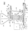
- Said figures show a usual ceramic press 1, on which in the illustrated example there is mounted a mould 2 with three cavities.
- a loading device 4 On the feed side of said press there is positioned a loading device 4 which can be moved translationally between an advanced position and a withdrawn position by the action of a geared electric motor unit 5.
- the geared motor unit 5 rotates a connecting rod 6 connected to the frame 7 of the collection belt 8 of the loading device 4.
- the collection belt 8 extends between a motorized rear roller 9 and an idle front roller 10, with which there is associated a usual pusher with scraper 333 for discharging the formed tiles and removing excess powder mixture.
- the motorized rear roller 9 is driven by a geared electric motor unit 11 via a toothed belt transmission 12 and a free-wheel pulley 14.
- the free wheel 14 transmits motion only in the direction of advancement of the belt 8 towards the press.
- the belt remains stationary, whereas during the withdrawal of the frame 7 in the opposite direction the belt 8 advances through a distance equal to the distance through which the frame 7 has withdrawn.
- the collection belt 8 is overlaid by a first feed belt 17 above which there is a hopper 18 and which is operated when required by a geared electric motor unit, not shown, and a second feed belt 19, coplanar with the first and above which there are four transverse hoppers A1, B1, C1, D1.
- the hopper 18 and the hoppers A1...D1 which are provided with lower closure gates, are as wide as the front of the press and as the underlying belts 17, 19 and 8, are overlaid by a traversing distributor 181, 20, 21, 22, 23 respectively, which receives a flexible feed tube 182, 200, 201, 202, 203 respectively.
- the flexible tube 182 is connected to an overlying silo, not shown.
- the flexible tubes 200, 201, 202 and 203 are connected to overlying collection vessels A, B, C and D respectively, containing four different types of mixture of powder material.
- the hoppers A1...D1 are movable vertically from a position adjacent to the belt 19, to a raised position.
- the belt 24 is as wide as the underlying belt 8 and carries a succession of decoration screens 241 arranged in lines of three (see Figure 4).
- a hopper 33 provided with a lower closure gate, not shown, and served by a feeder 25 driven with reciprocating movement and connected to an overlying material container, not shown, by the flexible tube 34.
- At least one of the rollers 240 is motorized in order to drive the belt 24 so as to bring the desired line of decoration screens 241 into the horizontal flat position.
- the collection vessels A, B, C and D are overlaid by a distributor belt 26 passing about two rollers 260 mounted on a frame 27 which can be moved translationally in a horizontal direction to position the end of the belt 26 above one or another of said collection vessels.
- a loading belt 28 which passes about two rollers 280 fixed to the machine base and is positioned below four large vessels or silos 29, 30, 31 and 32, each of which is provided with a lower closure gate, not shown, and contains single-colour powder of various qualities.
- a blade mixer 36 or equivalent driven by a geared motor unit 35, which is operated when desired.
- the drive means for the belts 26 and 28 and for the frame 27 will not be described as they are of usual type.
- the belt 26 By horizontal translational shifting, the belt 26 causes its end to lie above that collection vessel A, B, C or D to receive the prepared material mixture, which is then discharged into it.
- Each vessel feeds the underlying hopper A1, B1, C1, D1 via the respective flexible tube 200, 201, 202, 203 and the respective reciprocating feeder 20, 21, 22, 23.
- Control means of usual type ensure that a sufficient quantity of material is present in each of said vessels and said hoppers, each of which hence contains a material of different quality.
- the hopper 18 containing the base material and the hopper 33 containing the decoration material are kept fed by analogous means, not shown.
- the powder layer is made to advance by the belt 8 until, on passing below the end of the belt 19 at the same speed thereas, it receives a convenient layer of background material discharged in the illustrated example by the hopper C1, which at the appropriate moment is closed and raised into its rest position.
- the cycle can be repeated either as such or in a simplified form.
- the loading device 4 shown in Figure 1 is formed as shown in Figure 6, in which it consists of a single frame 7 which supports two aligned collection belts 81 and 82 and is connected to the geared motor unit 5 via the connecting rod 6.
- the belts 81 and 82 are moved in opposite directions.
- the hopper 33 causes a certain quantity of powder material to fall through the decoration screens 241, to form a powder pattern on the underlying collection belt 82.
- the pattern so formed is advanced by the belt 82 as far as the front end of the feed belt 19, which advances at the same speed as the belt 82 to deposit on the powder pattern a uniform layer of background material created by one of the hoppers A1....D1 on said belt 19.
- the hopper 18 deposits the base material on the feed belt 17, which deposits it on the collection belt which advances at the same speed thereas.
- the frame 7 is made to move translationally until positioned as shown in the figure with dashed lines and is then made to withdraw while the belt 82 advances because of the provision of the rack 16 and free-wheel pinion 15, to discharge the two layers (pattern and background) in the mould 2.
- the belt 81 begins to advance, at the withdrawal speed of the frame 70, when its left end is in correspondence with the left end of the mould 2, so as to discharge the base material into the mould.
- the tile is formed inverted, ie with its exposed side facing downwards, however it could evidently be formed the right way up.
- the plant shown in Figure 7 is used, in which the tile base material depositing device, consisting of the elements 17, 18, 180, 181, 182 shown in Figure 1, is positioned upstream of the device which deposits the material forming the tile background.
Landscapes
- Engineering & Computer Science (AREA)
- Manufacturing & Machinery (AREA)
- Chemical & Material Sciences (AREA)
- Ceramic Engineering (AREA)
- Mechanical Engineering (AREA)
- Press-Shaping Or Shaping Using Conveyers (AREA)
- Devices For Post-Treatments, Processing, Supply, Discharge, And Other Processes (AREA)
Claims (13)
- Procédé de chargement d'une masse molle composite dans les moules (2) de pressage des carreaux en céramique, lesdits moules comportant au moins un creuset de formage (3) pour la compression des carreaux, caractérisé en ce qu'il comprend les étapes suivantes :placer provisoirement au moins une couche de matériau pulvérulent sur chacun des premier et deuxième convoyeurs coplanaires (81, 82), supportés par un même châssis mais opérant dans des directions opposées ;au moyen desdits convoyeurs, transporter successivement dans au moins l'un desdits creusets les couches de matériau pulvérulent placées sur les convoyeurs, sans les mélanger ni sans leur faire subir aucun déplacement horizontal.
- Procédé selon la revendication 1, caractérisé en ce que le transport est effectué en faisant s'arrêter le premier convoyeur (82) juste au-dessus du creuset de moulage, et qui consiste ensuite à retirer le convoyeur tout en l'actionnant simultanément pour le faire avancer dans la direction opposée à la même vitesse que celle à laquelle il est retiré, puis à faire de même avec le deuxième convoyeur (81) lorsqu'il se trouve juste au-dessus du creuset de moulage, toujours à la même vitesse que celle à laquelle il est retiré et dans la direction opposée.
- Procédé selon la revendication 1, caractérisé en ce que le matériau pulvérulent placé sur le premier convoyeur est un matériau pulvérulent coloré.
- Procédé selon la revendication 3, caractérisé en ce que la couche de matériau pulvérulent coloré est placée sur le premier convoyeur par l'intermédiaire de dispositifs conçus de manière à intercepter l'écoulement du matériau pour le façonner selon un modèle décoratif souhaité.
- Procédé selon la revendication 4, caractérisé en ce que ces dispositifs d'interception sont des gabarits.
- Procédé selon la revendication 1, caractérisé en ce que sont placées sur ledit premier convoyeur au moins deux couches de matériau pulvérulent.
- Procédé selon la revendication 6, caractérisé en ce qu'au moins deux desdites couches sont constituées de matériau pulvérulent de différentes couleurs.
- Installation pour alimenter un moule à pressage (2) des carreaux de céramique équipé au moins d'un creuset de formage (3), qui comprend un dispositif de chargement (4) positionné devant le moule, conçu de manière à coulisser entre une première position où il se trouve à distance dudit moule et une deuxième position où il le recouvre, équipée d'une surface horizontale mobile par rapport audit dispositif de chargement et d'une première unité de distribution du matériau pulvérulent (33), conçue de façon à former une couche sur ladite surface;
telle surface étant disposée de manière à coulisser par rapport à la structure du dispositif en question, afin de placer ladite masse molle dans ledit creuset sans la soumettre à aucun déplacement horizontal, caractérisée en ce que ladite surface comprend au moins deux convoyeurs coplanaires de ramassage (81, 82), pilotés de façon à déverser dans le creuset de formage les couches de matériau déposées sur les convoyeurs à travers l'espace qui les sépare. - Installation selon la revendication 8, caractérisée en ce que ledit dispositif de chargement (4) comprend un châssis horizontal (7) qui supporte lesdits convoyeurs coplanaires de ramassage (81, 82), et dont le bord avant est équipé d'un poussoir muni d'un racleur (33) disposé pour enlever du moule les carreaux pressés (14) et nettoyer la surface de pressage.
- Installation selon les revendications 8 et 9 ci-dessus, caractérisée en ce que chacun desdits convoyeurs de ramassage (81, 82) est piloté par une unité motorisée disposée pour provoquer un changement de direction à une vitesse égale, en valeur absolue, à la vitesse avec laquelle le dispositif (4) se déplace de ladite seconde position vers ladite première position ou vice-versa.
- Installation selon les revendications de 8 à 10 ci-dessus, caractérisée en ce qu'elle comprend au moins un convoyeur intermédiaire se superposant à au moins un convoyeur de ramassage, ainsi qu'une deuxième unité de distribution pour placer ledit matériau pulvérulent sur ledit convoyeur intermédiaire.
- Installation selon les revendications de 8 à 11 ci-dessus, caractérisée en ce que la deuxième unité de distribution comprend au moins l'une des trémies (A1, ... D1) placées en série au-dessus dudit convoyeur intermédiaire.
- Installation selon les revendications de 8 à 12 ci-dessus, caractérisée en ce que la première unité de distribution comprend au moins une trémie (33, 55) alimentée par un dispositif à mouvement alternatif (25, 57) équipé d'un embout de sortie placé au-dessus d'un gabarit de quadrillage (241, 530) qui intercepte l'écoulement du matériau pour le sélectionner en fonction d'un modèle prédéterminé.
Applications Claiming Priority (2)
| Application Number | Priority Date | Filing Date | Title |
|---|---|---|---|
| ITRE960061 | 1996-07-30 | ||
| IT96RE000061A IT1287758B1 (it) | 1996-07-30 | 1996-07-30 | Sistema di caricamento degli stampi delle presse ceramiche per la formatura di piastrelle pressosmaltate, e relativi mezzi di attuazione |
Publications (2)
| Publication Number | Publication Date |
|---|---|
| EP0822044A1 EP0822044A1 (fr) | 1998-02-04 |
| EP0822044B1 true EP0822044B1 (fr) | 2002-09-18 |
Family
ID=11398932
Family Applications (1)
| Application Number | Title | Priority Date | Filing Date |
|---|---|---|---|
| EP97202274A Expired - Lifetime EP0822044B1 (fr) | 1996-07-30 | 1997-07-21 | Dispositif d'alimentation pour moules dans les presses pour la fabrication de carreaux en céramique émaillés pressés et moyens de mise en oeuvre correspondants |
Country Status (5)
| Country | Link |
|---|---|
| EP (1) | EP0822044B1 (fr) |
| AT (1) | ATE224275T1 (fr) |
| DE (1) | DE69715539T2 (fr) |
| ES (1) | ES2184026T3 (fr) |
| IT (1) | IT1287758B1 (fr) |
Cited By (1)
| Publication number | Priority date | Publication date | Assignee | Title |
|---|---|---|---|---|
| WO2025247960A1 (fr) * | 2024-05-29 | 2025-12-04 | Putzmeister Engineering Gmbh | Système de bétonnage pour la fabrication d'éléments préfabriqués en béton et procédé pour faire fonctionner un système de bétonnage |
Families Citing this family (17)
| Publication number | Priority date | Publication date | Assignee | Title |
|---|---|---|---|---|
| IT1292745B1 (it) | 1997-06-10 | 1999-02-11 | Alberto Franceschini | Procedimento ed impianto per la formatura di piastrelle ceramiche e simili. |
| IT1298003B1 (it) * | 1997-12-11 | 1999-12-20 | Ariostea Societa Per Azioni | Metodo e dispositivo di caricamento degli stampi delle presse ceramiche |
| IT1298598B1 (it) * | 1998-03-06 | 2000-01-12 | Marazzi Ceramica | Macchina per la produzione di piastrelle con variazione di colore nella massa |
| IT1303927B1 (it) * | 1998-03-10 | 2001-03-01 | Lb Officine Meccaniche Spa | Metodo di fabbricazione di piastrella decorata,relativo dispositivo di caricamento degli stampi della pressa e piastrella cosi' fabbricata. |
| IT1304615B1 (it) * | 1998-04-15 | 2001-03-28 | Ceramica Monital Spa | Dispositivo di caricamento per una pressa ceramica |
| ES2143949B1 (es) * | 1998-05-05 | 2000-12-01 | Lb Officine Meccaniche Spa | Aparato para cargar materiales a granel en la cavidad del molde en prensas para la formacion de baldosas. |
| IT1306079B1 (it) * | 1998-06-02 | 2001-05-29 | Ariostea S P A | Dispositivo di alimentazione delle polveri alla pressa di formatura di piastrelle ceramiche |
| IT1306349B1 (it) * | 1998-08-21 | 2001-06-06 | Merli Fabio | Dispositivo di alimentazione della cavita' dello stampo nellepresse per ceramica e prodotto relativo |
| ITMO20010175A1 (it) * | 2001-08-28 | 2003-02-28 | R P Srl | Testa di scarico di trasportatore a nastro |
| ITMO20050106A1 (it) * | 2005-04-29 | 2006-10-30 | R P Srl | Apparato, e metodo, per l'alimentazione di stampi pressa, nella formatura di piastrelle o prodotti simili. |
| DE102005042456A1 (de) * | 2005-09-06 | 2007-05-16 | Karl Engelhardt | MATRIX-Belag Verfahren zur Herstellung von Fliesen- und Plattenbelägen mit frei definierbaren, skalierbaren Rasterbild-Dekoren |
| CN100463788C (zh) * | 2005-11-03 | 2009-02-25 | 唐君 | 一种仿大理石线条的陶瓷砖的布料方法及布料设备 |
| ITFI20070041A1 (it) * | 2007-02-20 | 2008-08-21 | O C E M Officina Costruzioni Elettro Meccaniche | Attrezzatura per alimentare il materiale agli stampi per mattonelle di graniglia e cemento. |
| IT201800006899A1 (it) * | 2018-07-03 | 2020-01-03 | Dispositivo applicatore per la decorazione di prodotti ceramici | |
| WO2020062300A1 (fr) * | 2018-09-30 | 2020-04-02 | 东莞市唯美陶瓷工业园有限公司 | Dispositif de distribution de matériau de manipulateur dans lequel une texture de corps de carreau de céramique et un motif de décoration de surface sont cohérents, et procédé de commande pour la distribution de matériau de manipulateur et l'ajustement de motif |
| CN114619553B (zh) * | 2022-02-28 | 2024-06-07 | 广东简一(集团)陶瓷有限公司 | 一种新型岩板通体瓷砖的精细化布料方法 |
| CN117283698A (zh) * | 2023-10-27 | 2023-12-26 | 佛山市东鹏陶瓷有限公司 | 一种通体仿天然石材的生态石干法布料的高效生产线 |
Family Cites Families (8)
| Publication number | Priority date | Publication date | Assignee | Title |
|---|---|---|---|---|
| LU34512A1 (fr) * | ||||
| FR2006826A1 (en) * | 1968-04-24 | 1970-01-02 | Ludowici Michael | Press for ceramic moulding with moving belt feed - mechanism |
| NL8701601A (nl) * | 1987-07-08 | 1989-02-01 | Mosa Koninkl Bv | Set vloertegels, werkwijze voor het vervaardigen van een vloertegel behorende tot de set en inrichting voor het uitvoeren van de werkwijze. |
| IT1239147B (it) * | 1990-02-26 | 1993-09-28 | L B Officine Meccaniche | Carrello a doppio caricamento per stampi ceramici in genere, tipicamente per la fabbricazione di piastrelle pressosmaltate. |
| JPH0822535B2 (ja) * | 1991-10-18 | 1996-03-06 | 株式会社日型 | 粉体原料充填方法及び粉体原料充填装置 |
| JPH07117039A (ja) * | 1993-10-26 | 1995-05-09 | Inax Corp | 二層式タイル成型方法 |
| JP2946169B2 (ja) * | 1993-12-30 | 1999-09-06 | 株式会社イナックス | 二層形タイルの成形方法 |
| IT1269274B (it) * | 1994-11-22 | 1997-03-26 | Carlo Antonio Camorani | Metodo per la formatura di piastrelle ceramiche ed impianto relativo |
-
1996
- 1996-07-30 IT IT96RE000061A patent/IT1287758B1/it active IP Right Grant
-
1997
- 1997-07-21 EP EP97202274A patent/EP0822044B1/fr not_active Expired - Lifetime
- 1997-07-21 DE DE69715539T patent/DE69715539T2/de not_active Expired - Fee Related
- 1997-07-21 AT AT97202274T patent/ATE224275T1/de not_active IP Right Cessation
- 1997-07-21 ES ES97202274T patent/ES2184026T3/es not_active Expired - Lifetime
Cited By (1)
| Publication number | Priority date | Publication date | Assignee | Title |
|---|---|---|---|---|
| WO2025247960A1 (fr) * | 2024-05-29 | 2025-12-04 | Putzmeister Engineering Gmbh | Système de bétonnage pour la fabrication d'éléments préfabriqués en béton et procédé pour faire fonctionner un système de bétonnage |
Also Published As
| Publication number | Publication date |
|---|---|
| ITRE960061A1 (it) | 1998-01-30 |
| DE69715539T2 (de) | 2003-01-16 |
| ES2184026T3 (es) | 2003-04-01 |
| ITRE960061A0 (it) | 1996-07-30 |
| IT1287758B1 (it) | 1998-08-18 |
| DE69715539D1 (de) | 2002-10-24 |
| ATE224275T1 (de) | 2002-10-15 |
| EP0822044A1 (fr) | 1998-02-04 |
Similar Documents
| Publication | Publication Date | Title |
|---|---|---|
| EP0822044B1 (fr) | Dispositif d'alimentation pour moules dans les presses pour la fabrication de carreaux en céramique émaillés pressés et moyens de mise en oeuvre correspondants | |
| US5056998A (en) | Apparatus for producing a set of mutually distinguishable flooring tiles | |
| CN1906001B (zh) | 用于预布置形成瓷砖或板的粉末的方法和设备 | |
| EP0894591B1 (fr) | Dispositif d'alimentation pour les moules des presses utilisées dans la fabrication de carreaux et moyens de mise en oeuvre correspondants | |
| EP0941826B1 (fr) | Méthode pour la fabrication d'un carreau décoré , dispositif correspondant pour l'alimentation des moules de pressage et carreau ainsi obtenu | |
| CN108527631B (zh) | 一种具有间隔条纹纹理布料砖的布料设备及布料方法 | |
| EP2318189B1 (fr) | Système de charge de presses pour produits en céramique | |
| CN112805129A (zh) | 用于将粒状材料给送至用于生产板或砖的设施的设备和方法 | |
| EP0693352B1 (fr) | Dispositif pour l'alimentation d'un chariot de remplissage de moules lors de la fabrication de carreaux de céramique | |
| EP0492733B1 (fr) | Dispositif et méthode pour la fabrication de carreaux en céramique | |
| EP0444730B1 (fr) | Chariot de remplissage double pour l'alimentation de moules pour céramique, en particulier pour la fabrication de carreaux pressés émaillés | |
| EP1005967A1 (fr) | Procédé et dispositif d'alimentation pour moules dans les presses pour la fabrication de carreaux en céramique émaillés pressés | |
| WO2005025829A1 (fr) | Procede et installation pour former des plaques ou des dalles ceramiques | |
| EP0940234B1 (fr) | Méthode et dispositif pour la fabrication de carreaux en céramique | |
| ITMO970107A1 (it) | Procedimento ed impianto per la formatura di piastrelle ceramiche e si mili | |
| EP0922549B1 (fr) | Procédé et dispositif pour le remplissage des moules d'une presse avec de la céramique | |
| EP0909622B1 (fr) | Dispositif et méthode pour remplir la cavité d'un moule avec un matériau en poudre ou granulaire dans la fabrication de carreaux en céramique | |
| EP0873832A1 (fr) | Dispositif pour le pressage de carreaux en céramique comportant deux couches | |
| EP1737631A2 (fr) | Appareils et procedes | |
| WO2002007939A1 (fr) | Systeme d'alimentation d'une presse de ceramiques | |
| EP1321260B1 (fr) | Procédé et installation pour la fabrication de carreaux ou dalles en céramique | |
| EP1773553B1 (fr) | Installation pour l'apport d'une double couche de poudre ou de materiau granulaire dans la cavite d'un moule pour la production de carreau de ceramique | |
| WO2003099737A2 (fr) | Appareil et procede pour fabriquer des carreaux ceramiques decores | |
| JPH0260487B2 (fr) | ||
| EP1129834A2 (fr) | Dispositif d'alimentation d'un moule avec des matières céramiques |
Legal Events
| Date | Code | Title | Description |
|---|---|---|---|
| PUAI | Public reference made under article 153(3) epc to a published international application that has entered the european phase |
Free format text: ORIGINAL CODE: 0009012 |
|
| AK | Designated contracting states |
Kind code of ref document: A1 Designated state(s): AT BE CH DE DK ES FI FR GB GR IE IT LI LU MC NL PT SE |
|
| AX | Request for extension of the european patent |
Free format text: AL;LT;LV;RO;SI |
|
| 17P | Request for examination filed |
Effective date: 19980722 |
|
| AKX | Designation fees paid |
Free format text: AT BE CH DE DK ES FI FR GB GR IE IT LI LU MC NL PT SE |
|
| RBV | Designated contracting states (corrected) |
Designated state(s): AT BE CH DE DK ES FI FR GB GR IE IT LI LU MC NL PT SE |
|
| RAP1 | Party data changed (applicant data changed or rights of an application transferred) |
Owner name: IRIS CERAMICA - SOCIETA' PER AZIONI Owner name: CERAMICHE PROVENZA S.R.L. |
|
| 17Q | First examination report despatched |
Effective date: 20010116 |
|
| GRAG | Despatch of communication of intention to grant |
Free format text: ORIGINAL CODE: EPIDOS AGRA |
|
| GRAG | Despatch of communication of intention to grant |
Free format text: ORIGINAL CODE: EPIDOS AGRA |
|
| GRAH | Despatch of communication of intention to grant a patent |
Free format text: ORIGINAL CODE: EPIDOS IGRA |
|
| GRAH | Despatch of communication of intention to grant a patent |
Free format text: ORIGINAL CODE: EPIDOS IGRA |
|
| GRAH | Despatch of communication of intention to grant a patent |
Free format text: ORIGINAL CODE: EPIDOS IGRA |
|
| GRAA | (expected) grant |
Free format text: ORIGINAL CODE: 0009210 |
|
| AK | Designated contracting states |
Kind code of ref document: B1 Designated state(s): AT BE CH DE DK ES FI FR GB GR IE IT LI LU MC NL PT SE |
|
| PG25 | Lapsed in a contracting state [announced via postgrant information from national office to epo] |
Ref country code: NL Free format text: LAPSE BECAUSE OF FAILURE TO SUBMIT A TRANSLATION OF THE DESCRIPTION OR TO PAY THE FEE WITHIN THE PRESCRIBED TIME-LIMIT Effective date: 20020918 Ref country code: LI Free format text: LAPSE BECAUSE OF FAILURE TO SUBMIT A TRANSLATION OF THE DESCRIPTION OR TO PAY THE FEE WITHIN THE PRESCRIBED TIME-LIMIT Effective date: 20020918 Ref country code: GR Free format text: LAPSE BECAUSE OF FAILURE TO SUBMIT A TRANSLATION OF THE DESCRIPTION OR TO PAY THE FEE WITHIN THE PRESCRIBED TIME-LIMIT Effective date: 20020918 Ref country code: FR Free format text: LAPSE BECAUSE OF NON-PAYMENT OF DUE FEES Effective date: 20020918 Ref country code: FI Free format text: LAPSE BECAUSE OF FAILURE TO SUBMIT A TRANSLATION OF THE DESCRIPTION OR TO PAY THE FEE WITHIN THE PRESCRIBED TIME-LIMIT Effective date: 20020918 Ref country code: CH Free format text: LAPSE BECAUSE OF FAILURE TO SUBMIT A TRANSLATION OF THE DESCRIPTION OR TO PAY THE FEE WITHIN THE PRESCRIBED TIME-LIMIT Effective date: 20020918 Ref country code: BE Free format text: LAPSE BECAUSE OF FAILURE TO SUBMIT A TRANSLATION OF THE DESCRIPTION OR TO PAY THE FEE WITHIN THE PRESCRIBED TIME-LIMIT Effective date: 20020918 Ref country code: AT Free format text: LAPSE BECAUSE OF FAILURE TO SUBMIT A TRANSLATION OF THE DESCRIPTION OR TO PAY THE FEE WITHIN THE PRESCRIBED TIME-LIMIT Effective date: 20020918 |
|
| REF | Corresponds to: |
Ref document number: 224275 Country of ref document: AT Date of ref document: 20021015 Kind code of ref document: T |
|
| REG | Reference to a national code |
Ref country code: GB Ref legal event code: FG4D |
|
| REG | Reference to a national code |
Ref country code: CH Ref legal event code: EP |
|
| REG | Reference to a national code |
Ref country code: IE Ref legal event code: FG4D |
|
| REF | Corresponds to: |
Ref document number: 69715539 Country of ref document: DE Date of ref document: 20021024 |
|
| PG25 | Lapsed in a contracting state [announced via postgrant information from national office to epo] |
Ref country code: SE Free format text: LAPSE BECAUSE OF FAILURE TO SUBMIT A TRANSLATION OF THE DESCRIPTION OR TO PAY THE FEE WITHIN THE PRESCRIBED TIME-LIMIT Effective date: 20021218 Ref country code: DK Free format text: LAPSE BECAUSE OF FAILURE TO SUBMIT A TRANSLATION OF THE DESCRIPTION OR TO PAY THE FEE WITHIN THE PRESCRIBED TIME-LIMIT Effective date: 20021218 |
|
| PG25 | Lapsed in a contracting state [announced via postgrant information from national office to epo] |
Ref country code: PT Free format text: LAPSE BECAUSE OF FAILURE TO SUBMIT A TRANSLATION OF THE DESCRIPTION OR TO PAY THE FEE WITHIN THE PRESCRIBED TIME-LIMIT Effective date: 20021219 |
|
| NLV1 | Nl: lapsed or annulled due to failure to fulfill the requirements of art. 29p and 29m of the patents act | ||
| REG | Reference to a national code |
Ref country code: ES Ref legal event code: FG2A Ref document number: 2184026 Country of ref document: ES Kind code of ref document: T3 |
|
| REG | Reference to a national code |
Ref country code: CH Ref legal event code: PL |
|
| EN | Fr: translation not filed | ||
| PG25 | Lapsed in a contracting state [announced via postgrant information from national office to epo] |
Ref country code: LU Free format text: LAPSE BECAUSE OF NON-PAYMENT OF DUE FEES Effective date: 20030721 Ref country code: IE Free format text: LAPSE BECAUSE OF NON-PAYMENT OF DUE FEES Effective date: 20030721 Ref country code: GB Free format text: LAPSE BECAUSE OF NON-PAYMENT OF DUE FEES Effective date: 20030721 |
|
| PLBE | No opposition filed within time limit |
Free format text: ORIGINAL CODE: 0009261 |
|
| STAA | Information on the status of an ep patent application or granted ep patent |
Free format text: STATUS: NO OPPOSITION FILED WITHIN TIME LIMIT |
|
| PG25 | Lapsed in a contracting state [announced via postgrant information from national office to epo] |
Ref country code: MC Free format text: LAPSE BECAUSE OF NON-PAYMENT OF DUE FEES Effective date: 20030731 |
|
| 26N | No opposition filed |
Effective date: 20030619 |
|
| GBPC | Gb: european patent ceased through non-payment of renewal fee |
Effective date: 20030721 |
|
| REG | Reference to a national code |
Ref country code: IE Ref legal event code: MM4A |
|
| PGFP | Annual fee paid to national office [announced via postgrant information from national office to epo] |
Ref country code: ES Payment date: 20040628 Year of fee payment: 8 |
|
| PGFP | Annual fee paid to national office [announced via postgrant information from national office to epo] |
Ref country code: DE Payment date: 20040713 Year of fee payment: 8 |
|
| PG25 | Lapsed in a contracting state [announced via postgrant information from national office to epo] |
Ref country code: ES Free format text: LAPSE BECAUSE OF NON-PAYMENT OF DUE FEES Effective date: 20050722 |
|
| PG25 | Lapsed in a contracting state [announced via postgrant information from national office to epo] |
Ref country code: DE Free format text: LAPSE BECAUSE OF NON-PAYMENT OF DUE FEES Effective date: 20060201 |
|
| REG | Reference to a national code |
Ref country code: ES Ref legal event code: FD2A Effective date: 20050722 |
|
| PGFP | Annual fee paid to national office [announced via postgrant information from national office to epo] |
Ref country code: IT Payment date: 20100624 Year of fee payment: 14 |
|
| PG25 | Lapsed in a contracting state [announced via postgrant information from national office to epo] |
Ref country code: IT Free format text: LAPSE BECAUSE OF NON-PAYMENT OF DUE FEES Effective date: 20110721 |