EP0822050A1 - Machine à mouler par injection - Google Patents
Machine à mouler par injection Download PDFInfo
- Publication number
- EP0822050A1 EP0822050A1 EP19970112830 EP97112830A EP0822050A1 EP 0822050 A1 EP0822050 A1 EP 0822050A1 EP 19970112830 EP19970112830 EP 19970112830 EP 97112830 A EP97112830 A EP 97112830A EP 0822050 A1 EP0822050 A1 EP 0822050A1
- Authority
- EP
- European Patent Office
- Prior art keywords
- carrier
- mold
- tool
- frame
- injection molding
- Prior art date
- Legal status (The legal status is an assumption and is not a legal conclusion. Google has not performed a legal analysis and makes no representation as to the accuracy of the status listed.)
- Withdrawn
Links
- 238000001746 injection moulding Methods 0.000 title claims abstract description 7
- 238000005452 bending Methods 0.000 description 2
- 239000000969 carrier Substances 0.000 description 1
- 230000001447 compensatory effect Effects 0.000 description 1
- 239000012530 fluid Substances 0.000 description 1
- 239000000463 material Substances 0.000 description 1
- 238000004904 shortening Methods 0.000 description 1
Images

Classifications
-
- B—PERFORMING OPERATIONS; TRANSPORTING
- B30—PRESSES
- B30B—PRESSES IN GENERAL
- B30B15/00—Details of, or accessories for, presses; Auxiliary measures in connection with pressing
- B30B15/04—Frames; Guides
- B30B15/047—C-shaped frames
-
- B—PERFORMING OPERATIONS; TRANSPORTING
- B29—WORKING OF PLASTICS; WORKING OF SUBSTANCES IN A PLASTIC STATE IN GENERAL
- B29C—SHAPING OR JOINING OF PLASTICS; SHAPING OF MATERIAL IN A PLASTIC STATE, NOT OTHERWISE PROVIDED FOR; AFTER-TREATMENT OF THE SHAPED PRODUCTS, e.g. REPAIRING
- B29C45/00—Injection moulding, i.e. forcing the required volume of moulding material through a nozzle into a closed mould; Apparatus therefor
- B29C45/17—Component parts, details or accessories; Auxiliary operations
- B29C45/1761—Means for guiding movable mould supports or injection units on the machine base or frame; Machine bases or frames
-
- B—PERFORMING OPERATIONS; TRANSPORTING
- B29—WORKING OF PLASTICS; WORKING OF SUBSTANCES IN A PLASTIC STATE IN GENERAL
- B29C—SHAPING OR JOINING OF PLASTICS; SHAPING OF MATERIAL IN A PLASTIC STATE, NOT OTHERWISE PROVIDED FOR; AFTER-TREATMENT OF THE SHAPED PRODUCTS, e.g. REPAIRING
- B29C45/00—Injection moulding, i.e. forcing the required volume of moulding material through a nozzle into a closed mould; Apparatus therefor
- B29C45/17—Component parts, details or accessories; Auxiliary operations
- B29C45/64—Mould opening, closing or clamping devices
- B29C45/67—Mould opening, closing or clamping devices hydraulic
-
- B—PERFORMING OPERATIONS; TRANSPORTING
- B29—WORKING OF PLASTICS; WORKING OF SUBSTANCES IN A PLASTIC STATE IN GENERAL
- B29C—SHAPING OR JOINING OF PLASTICS; SHAPING OF MATERIAL IN A PLASTIC STATE, NOT OTHERWISE PROVIDED FOR; AFTER-TREATMENT OF THE SHAPED PRODUCTS, e.g. REPAIRING
- B29C45/00—Injection moulding, i.e. forcing the required volume of moulding material through a nozzle into a closed mould; Apparatus therefor
- B29C45/17—Component parts, details or accessories; Auxiliary operations
- B29C45/1761—Means for guiding movable mould supports or injection units on the machine base or frame; Machine bases or frames
- B29C2045/1768—Means for guiding movable mould supports or injection units on the machine base or frame; Machine bases or frames constructions of C-shaped frame elements
Definitions
- the invention relates to an injection molding machine with a stationary Machine frame, which carries a mold half immovably, and with one beams that can be moved relative to the machine frame for the second mold half, wherein this carrier has at least one extension which when the mold is closed is inserted below the immovable mold half, whereupon the Mold halves by a device for generating the closing pressure be pressed together.
- the invention is based on the consideration that the Length of conventional C-frame is essentially due to the fact that the closing force is applied by an appropriate device pressure on the back of the Carrier of the movable mold half applies.
- This facility for example, a Hydraulic cylinder or a toggle lever arrangement
- This facility not only has a specific one Minimum length, but must also be extended by the opening path of the mold be.
- the so-called cylinder plate By supporting the device for generating the closing force on one Tavern, the so-called cylinder plate, the C-frame is the Overall, the machine frame is very long.
- the invention leads to a substantial shortening of the machine frame by it is provided that the device for generating the closing pressure only on the extensions of the carrier running under the mold halves attacks.
- a device In a device according to the invention, it takes over the immovable Half of the mold bearing part of the frame the function of the cylinder plate.
- a The device according to the invention thus resembles a two-platen machine on (see AT-B 378 500), although the upper spars are omitted are. Since such spars have a function, such a omission is in the generally not be possible without compensatory measures.
- that at least one of the mold platens supporting the mold halves horizontal axes is pivotally mounted. If you are content with that at Applying the closing force swiveling and bending of the Machine parts carrying the mold halves by pivoting in opposite directions to compensate, both platen can rigidly on Stay attached. In this case, the machine frame does not have the shape a lying C, but a lying I. Due to the closing force spreading of the upper parts of the frame is achieved by spreading the lower parts Frame legs compensated where this is known from AT-B 361 220.
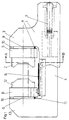
- Fig. 1 is a schematic side view of a first embodiment of the Invention
- Fig. 2 is a section along the line A-B in Fig. 1
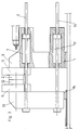
- Fig. 3 is the side view of a second embodiment.
- the injection molding device shown in FIGS. 1 and 2 has a fixed one Machine frame 1, which by means of a platen 5, the fixed Mold half 2 carries.
- the corresponding movable mold half 12 is by means of the Platen 6 mounted on a support 13.
- This carrier 13 is with a Extension 4 provided, which in a corresponding recess of the Machine frame 1 is movable, the platen 6 on a rail 8 of the frame 1 slides.
- this movement is carried out by a Hydraulic cylinder 7, which also applies the closing force.
- the invention is not on a hydraulic device for generating the rapid or power stroke limited.
- the movable support 13 is on the rail 15 of the machine frame 1 can be moved when fixed to the carrier 13 connected extensions 4 and 14 by means of the lock cylinders 7 and 17 and be retracted.
- the cylinders 7 and 17 actuated in the same direction, but to apply the closing force is in the left Cylinder chamber of the locking cylinder 7 hydraulic fluid, what without Countermeasures could lead to a gaping of the mold halves 2, 12.
- the lower extension 14 which is fixedly connected to the carrier 13, under pressure set until the contact surfaces of the mold halves 2 and 12 are parallel again.
Landscapes
- Engineering & Computer Science (AREA)
- Mechanical Engineering (AREA)
- Manufacturing & Machinery (AREA)
- Moulds For Moulding Plastics Or The Like (AREA)
Applications Claiming Priority (2)
| Application Number | Priority Date | Filing Date | Title |
|---|---|---|---|
| AT438/96U | 1996-07-26 | ||
| AT43896U AT1492U1 (de) | 1996-07-26 | 1996-07-26 | Spritzgiessmaschine |
Publications (1)
| Publication Number | Publication Date |
|---|---|
| EP0822050A1 true EP0822050A1 (fr) | 1998-02-04 |
Family
ID=3490620
Family Applications (1)
| Application Number | Title | Priority Date | Filing Date |
|---|---|---|---|
| EP19970112830 Withdrawn EP0822050A1 (fr) | 1996-07-26 | 1997-07-25 | Machine à mouler par injection |
Country Status (2)
| Country | Link |
|---|---|
| EP (1) | EP0822050A1 (fr) |
| AT (1) | AT1492U1 (fr) |
Cited By (1)
| Publication number | Priority date | Publication date | Assignee | Title |
|---|---|---|---|---|
| CN103252877A (zh) * | 2012-02-21 | 2013-08-21 | 住友重机械工业株式会社 | 注射成形机 |
-
1996
- 1996-07-26 AT AT43896U patent/AT1492U1/de not_active IP Right Cessation
-
1997
- 1997-07-25 EP EP19970112830 patent/EP0822050A1/fr not_active Withdrawn
Non-Patent Citations (1)
| Title |
|---|
| No relevant documents disclosed * |
Cited By (3)
| Publication number | Priority date | Publication date | Assignee | Title |
|---|---|---|---|---|
| CN103252877A (zh) * | 2012-02-21 | 2013-08-21 | 住友重机械工业株式会社 | 注射成形机 |
| EP2631057A1 (fr) * | 2012-02-21 | 2013-08-28 | Sumitomo Heavy Industries, Ltd. | Machine de moulage à injection |
| CN103252877B (zh) * | 2012-02-21 | 2016-01-20 | 住友重机械工业株式会社 | 注射成形机 |
Also Published As
| Publication number | Publication date |
|---|---|
| AT1492U1 (de) | 1997-06-25 |
Similar Documents
| Publication | Publication Date | Title |
|---|---|---|
| DE2146245C3 (de) | Formwerkzeuge, Insbesondere zum Herstellen von Formungen aus Polyurethan | |
| EP0722820A1 (fr) | Dispositif de fermeture de moule sans colonnes | |
| DE4313473C2 (de) | Schließeinheit für eine Spritzgießmaschine | |
| DE19609568C2 (de) | Druckausgleichsvorrichtung zur Kompensation von Verkantungen | |
| EP0745029B1 (fr) | Mecanisme de serrage de moule pour machines de moulage de matieres plastiques, notamment des machines de moulage par injection | |
| DE19539752C2 (de) | Holmlose Zwei-Platten-Spritzgießmaschine | |
| AT5360U1 (de) | Spritzgiesseinrichtung | |
| EP0576837A1 (fr) | Machine à mouler par injection avec moule à étages | |
| DD256477A5 (de) | Schliesseinheit fuer eine einrichtung zum spritzgiessen thermoplastischer kunststoffe | |
| DE19804143A1 (de) | Schließvorrichtung für Formen zum Herstellen von Gegenständen aus thermoplastischem Kunststoff | |
| EP0835733A1 (fr) | Presse d'injection avec un dispositif de fermeture | |
| AT411823B (de) | Spritzgiesseinrichtung | |
| AT427U1 (de) | Spritzgusseinrichtung fuer kunststoffe | |
| DE19510488C1 (de) | Vorrichtung zum Schließen von Formen für die Herstellung von Gegenständen aus Kunststoff | |
| DD259594A5 (de) | Schliesseinheit fuer eine einrichtung zum spritzgiessen | |
| DE20121500U1 (de) | Formschließvorrichtung für eine Spritzgießmaschine | |
| DE102005047995B4 (de) | Verfahren und Einrichtung zum Betrieb einer Spritzgießeinrichtung | |
| AT1492U1 (de) | Spritzgiessmaschine | |
| DE1910459A1 (de) | Formschliess- und Formzuhaltevorrichtung fuer insbesondere Kunststoffe oder sich aehnlich verhaltende Massen verarbeitende Spritzgiessmaschinen oder Pressen | |
| EP3024628B1 (fr) | Machine de moulage par injection avec une unité de fermeture | |
| DE2516018A1 (de) | Formschliessvorrichtung fuer giessmaschinen | |
| DE2520718A1 (de) | Giess- bzw. formungs-bedienungsvorrichtung | |
| EP4344852A1 (fr) | Dispositif de fabrication de corps creux | |
| DE9402825U1 (de) | Spritzgießmaschine | |
| AT403265B (de) | Einrichtung zum spritzgiessen von thermoplastischen kunststoffen |
Legal Events
| Date | Code | Title | Description |
|---|---|---|---|
| PUAI | Public reference made under article 153(3) epc to a published international application that has entered the european phase |
Free format text: ORIGINAL CODE: 0009012 |
|
| AK | Designated contracting states |
Kind code of ref document: A1 Designated state(s): AT BE CH DE DK ES FI FR GB GR IE IT LI LU MC NL PT SE |
|
| AX | Request for extension of the european patent |
Free format text: AL;LT;LV;RO;SI |
|
| AKX | Designation fees paid | ||
| RBV | Designated contracting states (corrected) | ||
| STAA | Information on the status of an ep patent application or granted ep patent |
Free format text: STATUS: THE APPLICATION IS DEEMED TO BE WITHDRAWN |
|
| 18D | Application deemed to be withdrawn |
Effective date: 19980805 |