EP0822076B1 - Tintenstrahlaufzeichnungsapparat und Steuerung desselben - Google Patents
Tintenstrahlaufzeichnungsapparat und Steuerung desselben Download PDFInfo
- Publication number
- EP0822076B1 EP0822076B1 EP97113271A EP97113271A EP0822076B1 EP 0822076 B1 EP0822076 B1 EP 0822076B1 EP 97113271 A EP97113271 A EP 97113271A EP 97113271 A EP97113271 A EP 97113271A EP 0822076 B1 EP0822076 B1 EP 0822076B1
- Authority
- EP
- European Patent Office
- Prior art keywords
- ejection
- electrodes
- control
- electrode
- voltage
- Prior art date
- Legal status (The legal status is an assumption and is not a legal conclusion. Google has not performed a legal analysis and makes no representation as to the accuracy of the status listed.)
- Expired - Lifetime
Links
- 239000013618 particulate matter Substances 0.000 claims description 21
- 238000000034 method Methods 0.000 claims description 13
- 230000005684 electric field Effects 0.000 description 9
- 238000001962 electrophoresis Methods 0.000 description 6
- 238000010586 diagram Methods 0.000 description 5
- 239000002245 particle Substances 0.000 description 5
- 230000005499 meniscus Effects 0.000 description 4
- 239000000758 substrate Substances 0.000 description 4
- 238000005054 agglomeration Methods 0.000 description 3
- 230000002776 aggregation Effects 0.000 description 3
- 239000007788 liquid Substances 0.000 description 2
- 230000005669 field effect Effects 0.000 description 1
- 239000011810 insulating material Substances 0.000 description 1
- 239000012212 insulator Substances 0.000 description 1
- 238000005192 partition Methods 0.000 description 1
- 239000000049 pigment Substances 0.000 description 1
Images


Classifications
-
- B—PERFORMING OPERATIONS; TRANSPORTING
- B41—PRINTING; LINING MACHINES; TYPEWRITERS; STAMPS
- B41J—TYPEWRITERS; SELECTIVE PRINTING MECHANISMS, i.e. MECHANISMS PRINTING OTHERWISE THAN FROM A FORME; CORRECTION OF TYPOGRAPHICAL ERRORS
- B41J2/00—Typewriters or selective printing mechanisms characterised by the printing or marking process for which they are designed
- B41J2/005—Typewriters or selective printing mechanisms characterised by the printing or marking process for which they are designed characterised by bringing liquid or particles selectively into contact with a printing material
- B41J2/01—Ink jet
- B41J2/015—Ink jet characterised by the jet generation process
- B41J2/04—Ink jet characterised by the jet generation process generating single droplets or particles on demand
- B41J2/06—Ink jet characterised by the jet generation process generating single droplets or particles on demand by electric or magnetic field
- B41J2002/061—Ejection by electric field of ink or of toner particles contained in ink
Definitions
- the present invention relates to an apparatus employing an inkjet recording method, and more particularly to an apparatus which ejects particulate matter such as pigment matter and toner matter from an ejection electrode by making use of an electric field and a control method for the apparatus.
- inkjet recording methods are extremely effective in that they are structurally simple and that they can perform high-speed recording directly onto ordinary medium.
- electrostatic inkjet recording method As one of the inkjet recording methods, there is an electrostatic inkjet recording method.
- the electrostatic inkjet recording apparatus generally has an electrostatic inkjet recording head and a counter electrode which is disposed behind the recording medium to form an electric field between it and the recording head.
- the electrostatic inkjet recording head has an ink chamber which temporarily stores ink containing toner particles and a plurality of ejection electrodes formed near the end of the ink chamber and directed toward the counter electrode.
- the ink near the front end of the ejection electrode forms a concave meniscus due to its surface tension, and consequently, the ink is supplied to the front end of the ejection electrode.
- the particulate matter in ink will be moved toward the front end of that ejection electrode by the electric field generated between the ejection electrode and the counter electrode.
- the coulomb force due to the electric field between the ejection electrode and the counter electrode considerably exceeds the surface tension of the ink liquid, the particulate matter reaching the front end of the ejection electrode is jetted toward the counter electrode as an agglomeration of particulate matter having a small quantity of liquid, and consequently, the jetted agglomeration adheres to the surface of the recording medium.
- An electrostatic inkjet apparatus according to the preamble of claim 1, and a control method for an electrostatic inkjet apparatus according to the preamble of claim 6, are disclosed, for example, in Japan Laid-Open Patent Publication No. 60-228162 and PCT International Publication No. WO93/11866.
- an electrostatic inkjet printer head where a plurality of ejection electrodes are disposed in an ink nozzle, and the front end of each ejection electrode is formed on the projecting portion of a head base which projects from the ink nozzle.
- the front end of this projecting portion has a pointed configuration, and the ejection electrode is formed in accordance with the direction of the pointed end.
- An ink meniscus is formed near the front end of the ejection electrode.
- the particulate matter when voltage pulses are consecutively applied to an ejection electrode in relatively short intervals, the particulate matter is supplied to the front end of the ejection electrode and then is jetted toward the counter electrode.
- the particulate matter withdraws from the front end of the ejection electrode because of reduced electrostatic force during the interval. In such a state, when the voltage pulse is applied, the particulate matter cannot be instantly jetted. Therefore, no ink may be jetted by that ejection electrode, resulting in deteriorated quality of printing.
- an ejection electrode which is not driven is grounded. Therefore, when an ejection electrode is driven and the adjacent ejection electrodes are not driven, an electric field is generated between the driven ejection electrode and the adjacent ejection electrodes. The electric field generated between them causes the particulate matter in the ink to drift away from the driven ejection electrode, resulting in deteriorated quality of printing.
- EP-A-0 778 138 which is comprised in the state of the art in the sense of Art. 54 (3) EPC, discloses an electrostatic inkjet device of a similar type wherein a plurality of auxiliary electrodes alternate with a plurality of ejection electrodes. The same as in the conventional inkjet device, an ejection voltage is applied to a selected ejection electrode to eject the ink. In addition, an auxiliary voltage higher than the ejection voltage is applied to two of the auxiliary electrodes joining the selected ejection electrode.
- An object of the present invention is to provide a method and apparatus which can eject ink from an ejection electrode with reliability and stability.
- Another object of the present invention is to provide a method and an apparatus which are capable of stably ejecting ink from a plurality of ejection electrodes.
- an electrostatic inkjet apparatus includes a plurality of ejection electrodes and a plurality of control electrodes.
- the ejection electrodes are arranged in an ink chamber for containing ink including particulate matter with protruding from a front end of the ink chamber.
- the control electrodes are arranged in the ink chamber such that each of the ejection electrodes is placed between two adjacent control electrodes.
- the apparatus further includes a controller which applies a control voltage to two control electrodes adjacent to a selected ejection electrode which is in a floating state to change a potential of the ejection electrode to an ejection level.
- the control voltage is not applied to the selected ejection electrode but the adjacent control electrodes, the equipotential surfaces are generated between the adjacent control electrodes and thereby the particulate matter around the selected ejection electrode is not caused to drift away from the selected ejection electrode. Therefore, the high quality of printing is achieved with reliability and stability.
- the controller may make the selected ejection electrode floating when it is designated as an ejection dot and applies the control voltage to the two control electrodes adjacent to the selected ejection electrode.
- the ejection electrodes may be electrically connected to each other with normally floating.
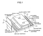
- a substrate 100 is made of an insulator such as plastic and has a plurality of ejection electrodes 101 and control electrodes 110 formed thereon which are coated with an insulating film. Each of the ejection electrodes 101 is placed in position between two adjacent control electrodes 110.
- An ink case 102 made of an insulating material is mounted on the substrate 100.
- the ink case 102 is formed with an ink supply port 103 and an ink discharge port 104.
- the space, defined by the substrate 100 and the ink case 102, constitutes an ink chamber which is filled with ink 105 containing toner particles which is supplied through the ink supply port 103.
- the front end of the ink case 102 is formed with a cutout to form a slit-shaped ink nozzle with flow partitions 106 between the ink case 102 and the substrate 100.
- the control electrodes 110 does not protrude from the ink nozzle but locate within the ink chamber.
- an electrophoresis electrode 107 is provided in contact with the ink 105 within the ink chamber. If voltage with the same polarity as toner particles is applied to the electrophoresis electrode 107, then an electric field will arise in the ink chamber between the electrode 107 and a counter electrode 108 which is grounded through a resistor, causing toner particles to be moved toward the ejection portions of the ejection electrode 101 due to the electrophoresis phenomenon, resulting in ink meniscus at each ejection portion.
- the potential of an ejection electrode for ink ejection is increased to more than a threshold level, the particulate matter is jetted from the front end of that ejection electrode toward a recording medium 109. In this manner, an image is formed on the recording medium 109.
- the potential of an ejection electrode for ink ejection is increased by two adjacent control electrodes 110 to which an ejection control voltage V c is concurrently applied.
- a voltage controller 201 generates voltages V 1 -V N applied to the ejection electrodes 101, respectively, and control voltages V C1 -V CN+1 applied to the control electrodes 110, respectively, under the control of a processor (CPU) 202.
- CPU central processing unit
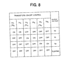
- the voltages V 1 -V N and the control voltages V C1 -V CN+1 are controlled such that each of the ejection electrodes 101 is set to one of a ground voltage (or non-ejection bias voltage V b ) and a floating state and each of the control electrodes 110 is set to one of an ejection control voltage V c and the ground voltage.
- the processor 202 performs the drive control of the inkjet device according to a control program stored in a read-only memory 203 and controls the voltage controller 201 depending on print data received from a computer 206 through an input interface 205. Further, the processor 202 instructs the voltage controller 201 to apply a predetermined voltage V D to the electrophoresis electrode 107. More specifically, when powered on, the processor 202 instructs the voltage controller 201 to apply the predetermined voltage V D to the electrophoresis electrode 107, causing an electric field to be generated in the ink chamber. The electric field moves the particulate matter such as toner particles toward the front ends of the ejection electrodes 101 due to the electrophoresis phenomenon and then the meniscuses 301 are formed at the front ends of the ejection electrodes 101. respectively.
- the voltage controller 201 makes the ejection electrode IJE i floating and then the ejection control voltage V C is applied to the control electrodes CE i and CE i+1 which are adjacent to both sides of the ejection electrode IJE i . Since the ejection electrodes IJE i is in the floating state, its potential is increased as shown by equipotential surfaces in Fig. 3, resulting in the dramatically reduced amount of the particulate matter in the ink drifting away from the ejection electrode IJE i .
- the electrostatic force between the ejection electrode IJE i and the counter electrode 108 is generated along the direction of ejection shown in Fig. 3.
- the respective voltages V Ci and V Ci+1 applied to the control electrodes CE i and CE i+1 fall from the ejection control voltage V c to the ground level, the particulate matter 302 is jetted from that ejection electrode IJE i toward the recording medium 109 as shown in Fig. 4.
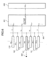
- the details of the ink ejection control will be described hereinafter referring to Fig. 5.
- the voltage controller 201 makes the ejection electrode IJE i-1 floating and outputs the ejection control voltage V C to the adjacent control electrodes CE i-1 and CE i for a predetermined period T C .
- the ejection control voltage V C causes the potential of the floating ejection electrode IJE i-1 to rise and then the particulate matter 302 is ejected when the voltages applied to the adjacent control electrodes CE i-1 and CE i fall to the ground voltage.
- the ejection electrode IJE i-1 is set to a predetermined voltage, for example, a bias voltage Vb by the voltage controller 201.
- the voltage controller 201 makes the ejection electrode IJE i floating and outputs the ejection control voltage V C to the adjacent control electrodes CE i and CE i+1 for the predetermined period T C .
- This causes the potential of the floating ejection electrode IJE i to rise and thereby the particulate matter 302 is ejected on the trailing edge of the pulse voltage V C as described before.
- the ejection electrode IJE i is set to a predetermined voltage, for example, a bias voltage Vb by the voltage controller 201.
- the voltage controller 201 makes the ejection electrode IJE i+1 floating and outputs the ejection control voltage V C to the adjacent control electrodes CE i+1 and CE i+2 for the predetermined period T C . This causes the particulate matter 302 to be ejected from the floating ejection electrode IJE i+1 on the trailing edge of the pulse voltage V C .
- all the ejection electrodes 110 may be connected in common to a floating line 303.
- the voltage controller 201 controls only the respective voltages applied to the control electrodes 110. Therefore, the voltage controller 201 can be realized with less amount of hardware and reduced complexity in circuit.
- the voltage controller 201 provides each ejection electrode or control electrode with a plurality of voltage states including the ground voltage and a floating state under control of the processor 202. If the respective voltages are generated by different power supply units, a plurality of power supply units are needed, resulting in the increased amount of hardware and the increased space and cost. Especially, when an electrode is made floating, a switch corresponding to that electrode is turned off to disconnect the electrode from all power supply units and the ground voltage. Since such a switch is provided for each electrode, high-speed switching is required to increase the inkjet recording speed.
- the voltage controller 201 which needs a single power supply unit but it can provide a plurality of voltage states including a floating state.
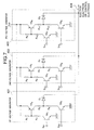
- a voltage control circuit connected to each ejection electrode or control electrode.
- the circuit is comprised of a first voltage generator 401, a second voltage generator 402, and a third voltage generator 403 which are supplied with a single power supply voltage V HD .
- the first to third voltage generators 401, 402 and 403 generate a bias voltage V b , an ejection control voltage V C , and other necessary voltage V P depending on a first control signal (S B1 and S B2 ), a second control signal (S C1 and S C2 ), and a third control signal (S P1 and S P2 ) received from the processor 202, respectively.
- the respective output terminals of the first to third voltage generators 401-403 are connected in common to an output line 404 which is connected to the corresponding single ejection electrode 101 or control electrode 110.
- the first voltage generator 401 is comprised of npn transistors TR 1 and TR 3 , a pnp transistor TR 2 , four resistors R 1 -R 4 and a diode D 1 .
- the control signals S B1 and S B2 are received at the bases of the transistors TR 1 and TR 3 , respectively, and the power supply voltage V HD is supplied to the emitter of the transistor TR 2 .
- the bias resistor R 1 is connected between the emitter and the base of the transistor TR 2 .
- the collector of the transistor TR 1 is connected to the base of the transistor TR 2 through the resistor R 2 .
- the respective collectors of the transistors TR 2 and TR 3 are connected through a series of resistors R 3 and R 4 .
- the respective emitters of the transistors TR 1 and TR 3 are grounded.
- the tap of the series of resistors R 3 and R 4 is connected to the output line 404 through the diode D 1 .
- V CE a collector-emitter voltage of the transistor TR 2 .
- the transistor TR 2 when the control signals S B1 and S B2 cause the transistors TR 2 and TR 3 to switch OFF, the transistor TR 2 is also turned off, the tap of the resistors R 3 and R 4 becomes floating.
- the first voltage V b is supplied to the output line 404 through the diode D 1 .
- the second and third voltage generator 402 and 403 have a circuit configuration similar to the first voltage generator 401.
- the second voltage generator 402 is comprised of npn transistors TR 4 and TR 6 , a pnp transistor TR 5 , four resistors R 5 -R 6 and a diode D 2 .
- the control signals S C1 and S C2 are received at the bases of the transistors TR 4 and TR 6 , respectively, and the power supply voltage V HD is supplied to the emitter of the transistor TR 5 .
- the bias resistor R 5 is connected between the emitter and the base of the transistor TR 5 .
- the collector of the transistor TR 4 is connected to the base of the transistor TR 5 through the resistor R 6 .
- the respective collectors of the transistors TR 5 and TR 6 are connected through a series of resistors R 7 and R 8 .
- the respective emitters of the transistors TR 4 and TR 6 are grounded.
- the tap of the series of resistors R 7 and R 8 is connected to the output line 404 through the diode D 2 .
- a desired voltage can be generated.
- a selected one of the first to third voltages V b , V C and V P is supplied to the output line 404 and further the output line 404 can be made floating according to the first to third control signals (S B1 and S B2 ), (S C1 and S C2 ), and (S P1 and S P2 ).
- the respective voltage generators are provided with the diodes D 1 , D 2 and D 3 at the output stages thereof such that each diode is reverse-biased when the voltage of the output line 404 is higher, the output line 404 has no influence on each voltage generator. Therefore, switching all the transistors TR 1 -TR 9 off causes the output line 404 to be made floating.
- FETs field effect transistors
- other switching devices may be used instead of bipolar transistors TR 1 -TR 9 .
Landscapes
- Particle Formation And Scattering Control In Inkjet Printers (AREA)
Claims (12)
- Elektrostatische Tintenstrahlvorrichtung mit:
einer Mehrzahl von Ausstoßelektroden (101), welche in einer Tintenkammer angeordnet sind, welche Tinte (105) mit Teilchen enthält, wobei die Ausstoßelektroden von einem vorderen Ende der Tintenkammer hervorstehen,
gekennzeichnet durch:eine Mehrzahl von Steuerungselektroden (110), welche in der Tintenkammer derart angeordnet sind, daß jede der Ausstoßelektroden zwischen zwei benachbarten Steuerungselektroden angeordnet ist; undeine Steuerungsvorrichtung (201) zum Anlegen einer Steuerungsspannung an zwei Steuerungselektroden, welche zu einer ausgewählten Ausstoßelektrode benachbart sind, welche in einem Schwebezustand ist, um das Potential der Ausstoßelektrode auf ein Ausstoßniveau zu verändern. - Elektrostatische Tintenstrahlvorrichtung nach Anspruch 1, bei welcher die Steuerungsvorrichtung die ausgewählte Ausstoßelektrode in Schwebezustand setzt, wenn sie als Ausstoßpunkt bestimmt ist, und die Steuerungsspannung an die zwei Steuerungselektroden anlegt, welche zu der ausgewählten Ausstoßelektrode benachbart sind.
- Elektrostatische Tintenstrahlvorrichtung nach Anspruch 1, bei welcher die Ausstoßelektroden normalerweise im Schwebezustand sind.
- Elektrostatische Tintenstrahlvorrichtung nach Anspruch 3, bei welcher die Ausstoßelektroden elektrisch in einem normalen Schwebezustand miteinander verbunden sind.
- Elektrostatische Tintenstrahlvorrichtung nach Anspruch 1, bei welcher die Steuerungsvorrichtung eine Mehrzahl von Spannungssteuerungsvorrichtungen umfaßt, wobei jede einer der Ausstoßelektroden und der Steuerungselektroden entspricht, und jede Spannungssteuerungsvorrichtung eine Ausgangsleitung (404) aufweist, welche mit einer entsprechenden der Ausstoßelektroden und der Steuerungselektroden verbunden ist,
wobei jede Spannungssteuerungsvorrichtung eine Mehrzahl von Spannungsgeneratoren (401-403) zum Erzeugen einer Mehrzahl von Spannungen einschließlich der Steuerungsspannung umfaßt und in-Schwebezustand-setzen der Ausgangsleitung gemäß einem Steuerungssignal, wobei jeder Spannungsgenerator mit einer vorbestimmten Netzspannung versorgt wird. - Steuerungsverfahren für eine elektrostatische Tintenstrahlvorrichtung mit:durch folgende Schritte gekennzeichnet:einer Mehrzahl von Ausstoßelektroden (101), welche in einer Tintenkammer angeordnet sind, welche Tinte mit Teilchen enthält, wobei die Ausstoßelektroden von einem vorderen Ende der Tintenkammer hervorstehen; undeiner Mehrzahl von Steuerungselektroden (110), welche in der Tintenkammer derart angeordnet sind, daß jede der Ausstoßelektroden zwischen zwei benachbarten Steuerungselektroden angeordnet ist,In-Schwebezustand-Setzen einer ausgewählten Ausstoßelektrode, welche als Ausstoßpunkt ausgewählt ist;Anlegen einer Steuerungsspannung an zwei Steuerungselektroden, welche zu der ausgewählten Ausstoßelektrode benachbart sind, welche in einem Schwebezustand ist, um das Potential der ausgewählten Ausstoßelektrode auf ein Ausstoßniveau zu verändern.
- Verfahren nach Anspruch 6, bei welchem die ausgewählte Ausstoßelektrode in Schwebezustand gesetzt wird, wenn sie als Ausstoßpunkt ausgewählt ist.
- Verfahren nach Anspruch 6, bei welchem die Ausstoßelektroden normalerweise im Schwebezustand sind.
- Elektrostatische Tintenstrahlvorrichtung nach Anspruch 1, welche weiter einen Datenprozessor (202) zum Verarbeiten von Druckdaten umfaßt, um Steuerungsdaten für die Ausstoßelektroden zu erzeugen, wobei die Steuerungsvorrichtung (201) ein Potential einer ausgewählten Ausstoßelektrode gemäß der vom Datenprozessor empfangenen Steuerungsdaten derart steuert, daß die ausgewählte Ausstoßelektrode in Schwebezustand gesetzt wird und eine Steuerungsspannung an zwei Steuerungselektroden angelegt wird, welche zu der ausgewählten Ausstoßelektrode benachbart sind, welche in einem Schwebezustand ist, um das Potential der Ausstoßelektrode auf ein Ausstoßniveau zu verändern.
- Elektrostatische Tintenstrahlvorrichtung nach Anspruch 1, bei welcher die Ausstoßelektroden mit einer Schwebeleitung (303) verbunden sind, ein Datenprozessor (202) zum Verarbeiten von Druckdaten bereitgestellt wird, um Steuerungsdaten für die Ausstoßelektroden zu erzeugen und die Steuerungsvorrichtung (201) ein Potential einer ausgewählten Ausstoßelektrode gemäß der vom Datenprozessor empfangenen Steuerungsdaten derart steuert, daß eine Steuerungsspannung an zwei Steuerungselektroden angelegt wird, welche zu der ausgewählten Ausstoßelektrode benachbart sind, um das Potential der Ausstoßelektrode auf ein Ausstoßniveau zu verändern.
- Elektrostatisches Tintenstrahlaufzeichnungssystem mit:einer Tintenstrahlvorrichtung gemäß Anspruch 1;einer Gegenelektrode (108) zum Erzeugen eines Potentials mit jeder der Ausstoßelektroden, um Tinte auf ein Aufzeichnungsmedium auszustoßen, welches auf der Gegenelektrode angeordnet ist;einem Datenprozessor (202) zum Verarbeiten von Druckdaten, um Steuerungsdaten für die Ausstoßelektroden zu erzeugen; undwobei die Steuerungsvorrichtung (201) ein Potential einer ausgewählten Ausstoßelektrode gemäß der vom Datenprozessor empfangenen Steuerungsdaten derart steuert, daß die ausgewählte Ausstoßelektrode in Schwebezustand gesetzt wird und eine Steuerungsspannung an zwei Steuerungselektroden angelegt wird, welche zu der ausgewählten Ausstoßelektrode benachbart sind, um das Potential der Ausstoßelektrode auf ein Ausstoßniveau zu verändern.
- Elektrostatisches Tintenstrahlaufzeichnungssystem mit:einer Tintenstrahlvorrichtung gemäß Anspruch 1, wobei die Ausstoßelektroden elektrisch mit einer Schwebeleitung (303) verbunden sind;einer Gegenelektrode (108) zum Erzeugen eines Potentials mit jeder der Ausstoßelektroden, um Tinte auf ein Aufzeichnungsmedium auszustoßen, welches auf der Gegenelektrode angeordnet ist;einem Datenprozessor (202) zum Verarbeiten von Druckdaten, um Steuerungsdaten für die Ausstoßelektroden zu erzeugen;wobei die Steuerungsvorrichtung (201) ein Potential einer ausgewählten Ausstoßelektrode gemäß der vom Datenprozessor empfangenen Steuerungsdaten derart steuert, daß eine Steuerungsspannung an zwei Steuerungselektroden angelegt wird, welche zu der ausgewählten Ausstoßelektrode benachbart sind, um das Potential der Ausstoßelektrode auf ein Ausstoßniveau zu verändern.
Applications Claiming Priority (6)
| Application Number | Priority Date | Filing Date | Title |
|---|---|---|---|
| JP20176196 | 1996-07-31 | ||
| JP20176196A JP2868473B2 (ja) | 1996-07-31 | 1996-07-31 | インクジェット記録装置 |
| JP201761/96 | 1996-07-31 | ||
| JP22610096 | 1996-08-09 | ||
| JP226100/96 | 1996-08-09 | ||
| JP22610096A JP2885714B2 (ja) | 1996-08-09 | 1996-08-09 | 静電式インクジェット記録装置 |
Publications (3)
| Publication Number | Publication Date |
|---|---|
| EP0822076A2 EP0822076A2 (de) | 1998-02-04 |
| EP0822076A3 EP0822076A3 (de) | 1998-07-08 |
| EP0822076B1 true EP0822076B1 (de) | 2001-11-07 |
Family
ID=26512969
Family Applications (1)
| Application Number | Title | Priority Date | Filing Date |
|---|---|---|---|
| EP97113271A Expired - Lifetime EP0822076B1 (de) | 1996-07-31 | 1997-07-31 | Tintenstrahlaufzeichnungsapparat und Steuerung desselben |
Country Status (3)
| Country | Link |
|---|---|
| US (1) | US6123416A (de) |
| EP (1) | EP0822076B1 (de) |
| DE (1) | DE69707989T2 (de) |
Families Citing this family (1)
| Publication number | Priority date | Publication date | Assignee | Title |
|---|---|---|---|---|
| GB2371267A (en) * | 2001-01-18 | 2002-07-24 | Tonejet Corp Pty Ltd | Drop-on-demand printer having an electrode located within a guard channel disposed between adjacent ink ejection channels to reduce electrostatic cross-talk |
Family Cites Families (5)
| Publication number | Priority date | Publication date | Assignee | Title |
|---|---|---|---|---|
| US4396925A (en) * | 1980-09-18 | 1983-08-02 | Matsushita Electric Industrial Co., Ltd. | Electroosmotic ink printer |
| JPS5814160A (ja) * | 1981-07-17 | 1983-01-26 | Ricoh Co Ltd | 静電記録方法 |
| US4710784A (en) * | 1985-07-11 | 1987-12-01 | Tokyo Electric Co., Ltd. | Ink jet printing device |
| EP0267782A3 (de) * | 1986-11-10 | 1989-09-27 | Kabushiki Kaisha Toshiba | Tintenstrahlsystem |
| JP2783226B2 (ja) * | 1995-12-06 | 1998-08-06 | 日本電気株式会社 | インクジェット式ヘッド装置 |
-
1997
- 1997-07-31 EP EP97113271A patent/EP0822076B1/de not_active Expired - Lifetime
- 1997-07-31 US US08/903,766 patent/US6123416A/en not_active Expired - Fee Related
- 1997-07-31 DE DE69707989T patent/DE69707989T2/de not_active Expired - Fee Related
Also Published As
| Publication number | Publication date |
|---|---|
| EP0822076A3 (de) | 1998-07-08 |
| DE69707989D1 (de) | 2001-12-13 |
| US6123416A (en) | 2000-09-26 |
| DE69707989T2 (de) | 2002-04-04 |
| EP0822076A2 (de) | 1998-02-04 |
Similar Documents
| Publication | Publication Date | Title |
|---|---|---|
| EP0013158B1 (de) | Elektrographische Spitzen-Schreibvorrichtung | |
| KR100871543B1 (ko) | 잉크젯 프린팅 시스템 및 잉크젯 프린트헤드 | |
| US4126867A (en) | Ink jet printer driving circuit | |
| KR100871542B1 (ko) | 잉크젯 프린트헤드 및 그 작동 방법 | |
| KR20080070603A (ko) | 잉크젯 프린트헤드 및 방울 발생기를 선택적으로활성화하는 방법 | |
| EP0838335B1 (de) | Tintenstrahlaufzeichnungsapparat | |
| EP0822076B1 (de) | Tintenstrahlaufzeichnungsapparat und Steuerung desselben | |
| JP3711447B2 (ja) | インクジェット式プリンタのヘッド駆動装置及び駆動方法 | |
| JP3757808B2 (ja) | インクジェット式プリンタのヘッド駆動装置及び駆動方法 | |
| JPS5849189B2 (ja) | インクジエツト用記録ヘツド | |
| EP0811496B1 (de) | Steuerung von Tintenstrahlausstosselektroden | |
| US6702418B2 (en) | Ink jet recording device capable of detecting defective nozzle with high signal-to-noise ratio | |
| JP3193126B2 (ja) | インクジェットヘッドの駆動装置 | |
| EP0893261B1 (de) | Tintenstrahlaufzeichnungsgerät und zugehöriges Steuerverfahren | |
| JP2885714B2 (ja) | 静電式インクジェット記録装置 | |
| US5997133A (en) | Inkjet recording apparatus having a minimum number of ejection electrode driving circuits and method for driving same | |
| JP3568010B2 (ja) | インクジェットプリンタのマトリックス駆動方式 | |
| JP2783206B2 (ja) | インクジェットプリンタ装置 | |
| JP4691776B2 (ja) | インクジェットヘッド駆動装置 | |
| JP2830864B2 (ja) | 静電式インクジェット記録装置 | |
| US6120122A (en) | Inkjet recording apparatus | |
| JP2001030497A (ja) | プリンタ | |
| JPH0444906B2 (de) | ||
| JPH01108055A (ja) | 静電型インクジェット記録装置 | |
| JPH05116287A (ja) | インクジエツトプリンタ |
Legal Events
| Date | Code | Title | Description |
|---|---|---|---|
| PUAI | Public reference made under article 153(3) epc to a published international application that has entered the european phase |
Free format text: ORIGINAL CODE: 0009012 |
|
| AK | Designated contracting states |
Kind code of ref document: A2 Designated state(s): DE FR GB |
|
| AX | Request for extension of the european patent |
Free format text: AL;LT;LV;RO;SI |
|
| PUAL | Search report despatched |
Free format text: ORIGINAL CODE: 0009013 |
|
| AK | Designated contracting states |
Kind code of ref document: A3 Designated state(s): AT BE CH DE DK ES FI FR GB GR IE IT LI LU MC NL PT SE |
|
| AX | Request for extension of the european patent |
Free format text: AL;LT;LV;RO;SI |
|
| 17P | Request for examination filed |
Effective date: 19980708 |
|
| AKX | Designation fees paid |
Free format text: DE FR GB |
|
| RBV | Designated contracting states (corrected) |
Designated state(s): DE FR GB |
|
| 17Q | First examination report despatched |
Effective date: 19990922 |
|
| GRAG | Despatch of communication of intention to grant |
Free format text: ORIGINAL CODE: EPIDOS AGRA |
|
| GRAG | Despatch of communication of intention to grant |
Free format text: ORIGINAL CODE: EPIDOS AGRA |
|
| GRAH | Despatch of communication of intention to grant a patent |
Free format text: ORIGINAL CODE: EPIDOS IGRA |
|
| GRAH | Despatch of communication of intention to grant a patent |
Free format text: ORIGINAL CODE: EPIDOS IGRA |
|
| GRAA | (expected) grant |
Free format text: ORIGINAL CODE: 0009210 |
|
| AK | Designated contracting states |
Kind code of ref document: B1 Designated state(s): DE FR GB |
|
| REF | Corresponds to: |
Ref document number: 69707989 Country of ref document: DE Date of ref document: 20011213 |
|
| REG | Reference to a national code |
Ref country code: GB Ref legal event code: IF02 |
|
| ET | Fr: translation filed | ||
| PLBE | No opposition filed within time limit |
Free format text: ORIGINAL CODE: 0009261 |
|
| STAA | Information on the status of an ep patent application or granted ep patent |
Free format text: STATUS: NO OPPOSITION FILED WITHIN TIME LIMIT |
|
| 26N | No opposition filed | ||
| PGFP | Annual fee paid to national office [announced via postgrant information from national office to epo] |
Ref country code: FR Payment date: 20060719 Year of fee payment: 10 |
|
| PGFP | Annual fee paid to national office [announced via postgrant information from national office to epo] |
Ref country code: GB Payment date: 20060726 Year of fee payment: 10 |
|
| PGFP | Annual fee paid to national office [announced via postgrant information from national office to epo] |
Ref country code: DE Payment date: 20060727 Year of fee payment: 10 |
|
| GBPC | Gb: european patent ceased through non-payment of renewal fee |
Effective date: 20070731 |
|
| PG25 | Lapsed in a contracting state [announced via postgrant information from national office to epo] |
Ref country code: DE Free format text: LAPSE BECAUSE OF NON-PAYMENT OF DUE FEES Effective date: 20080201 |
|
| PG25 | Lapsed in a contracting state [announced via postgrant information from national office to epo] |
Ref country code: GB Free format text: LAPSE BECAUSE OF NON-PAYMENT OF DUE FEES Effective date: 20070731 |
|
| REG | Reference to a national code |
Ref country code: FR Ref legal event code: ST Effective date: 20080331 |
|
| PG25 | Lapsed in a contracting state [announced via postgrant information from national office to epo] |
Ref country code: FR Free format text: LAPSE BECAUSE OF NON-PAYMENT OF DUE FEES Effective date: 20070731 |