EP0822077A2 - Tête d'éjection de liquide et procédé de sa fabrication - Google Patents
Tête d'éjection de liquide et procédé de sa fabrication Download PDFInfo
- Publication number
- EP0822077A2 EP0822077A2 EP97113006A EP97113006A EP0822077A2 EP 0822077 A2 EP0822077 A2 EP 0822077A2 EP 97113006 A EP97113006 A EP 97113006A EP 97113006 A EP97113006 A EP 97113006A EP 0822077 A2 EP0822077 A2 EP 0822077A2
- Authority
- EP
- European Patent Office
- Prior art keywords
- liquid
- orifices
- ejecting
- electrically connected
- depression region
- Prior art date
- Legal status (The legal status is an assumption and is not a legal conclusion. Google has not performed a legal analysis and makes no representation as to the accuracy of the status listed.)
- Granted
Links
- 238000004519 manufacturing process Methods 0.000 title claims description 18
- 238000007639 printing Methods 0.000 claims abstract description 101
- 239000011347 resin Substances 0.000 claims abstract description 60
- 229920005989 resin Polymers 0.000 claims abstract description 60
- 238000007789 sealing Methods 0.000 claims abstract description 55
- 239000007788 liquid Substances 0.000 claims abstract description 43
- 239000000463 material Substances 0.000 claims description 16
- 239000004744 fabric Substances 0.000 claims description 8
- 239000004033 plastic Substances 0.000 claims description 8
- 238000012545 processing Methods 0.000 claims description 8
- 238000009835 boiling Methods 0.000 claims description 6
- 229910010293 ceramic material Inorganic materials 0.000 claims description 4
- 239000007769 metal material Substances 0.000 claims description 4
- 239000000976 ink Substances 0.000 description 42
- 238000000034 method Methods 0.000 description 29
- 238000007641 inkjet printing Methods 0.000 description 18
- 230000008569 process Effects 0.000 description 12
- 239000000758 substrate Substances 0.000 description 9
- XUIMIQQOPSSXEZ-UHFFFAOYSA-N Silicon Chemical compound [Si] XUIMIQQOPSSXEZ-UHFFFAOYSA-N 0.000 description 8
- 239000000470 constituent Substances 0.000 description 8
- 229910052710 silicon Inorganic materials 0.000 description 8
- 239000010703 silicon Substances 0.000 description 8
- 238000011282 treatment Methods 0.000 description 8
- 239000010408 film Substances 0.000 description 7
- 239000010410 layer Substances 0.000 description 7
- 238000000206 photolithography Methods 0.000 description 7
- 238000002203 pretreatment Methods 0.000 description 6
- 239000004020 conductor Substances 0.000 description 5
- 229910052751 metal Inorganic materials 0.000 description 5
- 239000002184 metal Substances 0.000 description 5
- 230000015572 biosynthetic process Effects 0.000 description 4
- 239000003086 colorant Substances 0.000 description 4
- 239000010985 leather Substances 0.000 description 4
- 238000000059 patterning Methods 0.000 description 4
- 239000011241 protective layer Substances 0.000 description 4
- KWYUFKZDYYNOTN-UHFFFAOYSA-M Potassium hydroxide Chemical compound [OH-].[K+] KWYUFKZDYYNOTN-UHFFFAOYSA-M 0.000 description 3
- XSQUKJJJFZCRTK-UHFFFAOYSA-N Urea Chemical compound NC(N)=O XSQUKJJJFZCRTK-UHFFFAOYSA-N 0.000 description 3
- 230000005587 bubbling Effects 0.000 description 3
- 239000000919 ceramic Substances 0.000 description 3
- 239000010409 thin film Substances 0.000 description 3
- 239000002023 wood Substances 0.000 description 3
- RYGMFSIKBFXOCR-UHFFFAOYSA-N Copper Chemical compound [Cu] RYGMFSIKBFXOCR-UHFFFAOYSA-N 0.000 description 2
- 229910052782 aluminium Inorganic materials 0.000 description 2
- XAGFODPZIPBFFR-UHFFFAOYSA-N aluminium Chemical compound [Al] XAGFODPZIPBFFR-UHFFFAOYSA-N 0.000 description 2
- 230000000903 blocking effect Effects 0.000 description 2
- 238000005266 casting Methods 0.000 description 2
- 238000004891 communication Methods 0.000 description 2
- 229910052802 copper Inorganic materials 0.000 description 2
- 239000010949 copper Substances 0.000 description 2
- 238000010586 diagram Methods 0.000 description 2
- 239000000428 dust Substances 0.000 description 2
- 230000005611 electricity Effects 0.000 description 2
- 238000005516 engineering process Methods 0.000 description 2
- 238000005530 etching Methods 0.000 description 2
- 239000000835 fiber Substances 0.000 description 2
- 239000011521 glass Substances 0.000 description 2
- 230000006872 improvement Effects 0.000 description 2
- 238000012986 modification Methods 0.000 description 2
- 230000004048 modification Effects 0.000 description 2
- 238000000465 moulding Methods 0.000 description 2
- 230000009467 reduction Effects 0.000 description 2
- 230000003068 static effect Effects 0.000 description 2
- 239000004753 textile Substances 0.000 description 2
- UMGDCJDMYOKAJW-UHFFFAOYSA-N thiourea Chemical compound NC(N)=S UMGDCJDMYOKAJW-UHFFFAOYSA-N 0.000 description 2
- 238000011144 upstream manufacturing Methods 0.000 description 2
- XLYOFNOQVPJJNP-UHFFFAOYSA-N water Substances O XLYOFNOQVPJJNP-UHFFFAOYSA-N 0.000 description 2
- 235000017166 Bambusa arundinacea Nutrition 0.000 description 1
- 235000017491 Bambusa tulda Nutrition 0.000 description 1
- 241001330002 Bambuseae Species 0.000 description 1
- 241000283690 Bos taurus Species 0.000 description 1
- CBENFWSGALASAD-UHFFFAOYSA-N Ozone Chemical compound [O-][O+]=O CBENFWSGALASAD-UHFFFAOYSA-N 0.000 description 1
- 235000015334 Phyllostachys viridis Nutrition 0.000 description 1
- 230000002159 abnormal effect Effects 0.000 description 1
- 230000009471 action Effects 0.000 description 1
- 239000011425 bamboo Substances 0.000 description 1
- 239000011230 binding agent Substances 0.000 description 1
- 238000005422 blasting Methods 0.000 description 1
- 230000000740 bleeding effect Effects 0.000 description 1
- 239000004202 carbamide Substances 0.000 description 1
- 230000015556 catabolic process Effects 0.000 description 1
- 239000011248 coating agent Substances 0.000 description 1
- 238000000576 coating method Methods 0.000 description 1
- 238000010276 construction Methods 0.000 description 1
- 238000005520 cutting process Methods 0.000 description 1
- 230000006735 deficit Effects 0.000 description 1
- 238000006731 degradation reaction Methods 0.000 description 1
- 230000000994 depressogenic effect Effects 0.000 description 1
- 238000013461 design Methods 0.000 description 1
- 230000000694 effects Effects 0.000 description 1
- 238000009429 electrical wiring Methods 0.000 description 1
- PCHJSUWPFVWCPO-UHFFFAOYSA-N gold Chemical compound [Au] PCHJSUWPFVWCPO-UHFFFAOYSA-N 0.000 description 1
- 239000010931 gold Substances 0.000 description 1
- 229910052737 gold Inorganic materials 0.000 description 1
- 238000010438 heat treatment Methods 0.000 description 1
- 238000009413 insulation Methods 0.000 description 1
- 239000002649 leather substitute Substances 0.000 description 1
- 238000012423 maintenance Methods 0.000 description 1
- 230000003287 optical effect Effects 0.000 description 1
- 230000002093 peripheral effect Effects 0.000 description 1
- 238000007747 plating Methods 0.000 description 1
- 239000011120 plywood Substances 0.000 description 1
- 229920001721 polyimide Polymers 0.000 description 1
- 229920000642 polymer Polymers 0.000 description 1
- 238000003825 pressing Methods 0.000 description 1
- 230000002265 prevention Effects 0.000 description 1
- 230000001737 promoting effect Effects 0.000 description 1
- 238000011084 recovery Methods 0.000 description 1
- 150000003839 salts Chemical class 0.000 description 1
- 238000005549 size reduction Methods 0.000 description 1
- 239000002195 soluble material Substances 0.000 description 1
- 230000000007 visual effect Effects 0.000 description 1
- 238000005406 washing Methods 0.000 description 1
Images





Classifications
-
- B—PERFORMING OPERATIONS; TRANSPORTING
- B41—PRINTING; LINING MACHINES; TYPEWRITERS; STAMPS
- B41J—TYPEWRITERS; SELECTIVE PRINTING MECHANISMS, i.e. MECHANISMS PRINTING OTHERWISE THAN FROM A FORME; CORRECTION OF TYPOGRAPHICAL ERRORS
- B41J2/00—Typewriters or selective printing mechanisms characterised by the printing or marking process for which they are designed
- B41J2/005—Typewriters or selective printing mechanisms characterised by the printing or marking process for which they are designed characterised by bringing liquid or particles selectively into contact with a printing material
- B41J2/01—Ink jet
- B41J2/135—Nozzles
- B41J2/14—Structure thereof only for on-demand ink jet heads
-
- B—PERFORMING OPERATIONS; TRANSPORTING
- B41—PRINTING; LINING MACHINES; TYPEWRITERS; STAMPS
- B41J—TYPEWRITERS; SELECTIVE PRINTING MECHANISMS, i.e. MECHANISMS PRINTING OTHERWISE THAN FROM A FORME; CORRECTION OF TYPOGRAPHICAL ERRORS
- B41J2/00—Typewriters or selective printing mechanisms characterised by the printing or marking process for which they are designed
- B41J2/005—Typewriters or selective printing mechanisms characterised by the printing or marking process for which they are designed characterised by bringing liquid or particles selectively into contact with a printing material
- B41J2/01—Ink jet
- B41J2/135—Nozzles
- B41J2/14—Structure thereof only for on-demand ink jet heads
- B41J2/14016—Structure of bubble jet print heads
- B41J2/14024—Assembling head parts
-
- B—PERFORMING OPERATIONS; TRANSPORTING
- B41—PRINTING; LINING MACHINES; TYPEWRITERS; STAMPS
- B41J—TYPEWRITERS; SELECTIVE PRINTING MECHANISMS, i.e. MECHANISMS PRINTING OTHERWISE THAN FROM A FORME; CORRECTION OF TYPOGRAPHICAL ERRORS
- B41J2/00—Typewriters or selective printing mechanisms characterised by the printing or marking process for which they are designed
- B41J2/005—Typewriters or selective printing mechanisms characterised by the printing or marking process for which they are designed characterised by bringing liquid or particles selectively into contact with a printing material
- B41J2/01—Ink jet
- B41J2/135—Nozzles
- B41J2/14—Structure thereof only for on-demand ink jet heads
- B41J2/14016—Structure of bubble jet print heads
- B41J2/14072—Electrical connections, e.g. details on electrodes, connecting the chip to the outside...
-
- B—PERFORMING OPERATIONS; TRANSPORTING
- B41—PRINTING; LINING MACHINES; TYPEWRITERS; STAMPS
- B41J—TYPEWRITERS; SELECTIVE PRINTING MECHANISMS, i.e. MECHANISMS PRINTING OTHERWISE THAN FROM A FORME; CORRECTION OF TYPOGRAPHICAL ERRORS
- B41J2/00—Typewriters or selective printing mechanisms characterised by the printing or marking process for which they are designed
- B41J2/005—Typewriters or selective printing mechanisms characterised by the printing or marking process for which they are designed characterised by bringing liquid or particles selectively into contact with a printing material
- B41J2/01—Ink jet
- B41J2/135—Nozzles
- B41J2/16—Production of nozzles
- B41J2/1601—Production of bubble jet print heads
- B41J2/1603—Production of bubble jet print heads of the front shooter type
-
- B—PERFORMING OPERATIONS; TRANSPORTING
- B41—PRINTING; LINING MACHINES; TYPEWRITERS; STAMPS
- B41J—TYPEWRITERS; SELECTIVE PRINTING MECHANISMS, i.e. MECHANISMS PRINTING OTHERWISE THAN FROM A FORME; CORRECTION OF TYPOGRAPHICAL ERRORS
- B41J2/00—Typewriters or selective printing mechanisms characterised by the printing or marking process for which they are designed
- B41J2/005—Typewriters or selective printing mechanisms characterised by the printing or marking process for which they are designed characterised by bringing liquid or particles selectively into contact with a printing material
- B41J2/01—Ink jet
- B41J2/135—Nozzles
- B41J2/16—Production of nozzles
- B41J2/1621—Manufacturing processes
- B41J2/1623—Manufacturing processes bonding and adhesion
-
- B—PERFORMING OPERATIONS; TRANSPORTING
- B41—PRINTING; LINING MACHINES; TYPEWRITERS; STAMPS
- B41J—TYPEWRITERS; SELECTIVE PRINTING MECHANISMS, i.e. MECHANISMS PRINTING OTHERWISE THAN FROM A FORME; CORRECTION OF TYPOGRAPHICAL ERRORS
- B41J2/00—Typewriters or selective printing mechanisms characterised by the printing or marking process for which they are designed
- B41J2/005—Typewriters or selective printing mechanisms characterised by the printing or marking process for which they are designed characterised by bringing liquid or particles selectively into contact with a printing material
- B41J2/01—Ink jet
- B41J2/135—Nozzles
- B41J2/16—Production of nozzles
- B41J2/1621—Manufacturing processes
- B41J2/1625—Manufacturing processes electroforming
-
- B—PERFORMING OPERATIONS; TRANSPORTING
- B41—PRINTING; LINING MACHINES; TYPEWRITERS; STAMPS
- B41J—TYPEWRITERS; SELECTIVE PRINTING MECHANISMS, i.e. MECHANISMS PRINTING OTHERWISE THAN FROM A FORME; CORRECTION OF TYPOGRAPHICAL ERRORS
- B41J2/00—Typewriters or selective printing mechanisms characterised by the printing or marking process for which they are designed
- B41J2/005—Typewriters or selective printing mechanisms characterised by the printing or marking process for which they are designed characterised by bringing liquid or particles selectively into contact with a printing material
- B41J2/01—Ink jet
- B41J2/135—Nozzles
- B41J2/16—Production of nozzles
- B41J2/1621—Manufacturing processes
- B41J2/1626—Manufacturing processes etching
-
- B—PERFORMING OPERATIONS; TRANSPORTING
- B41—PRINTING; LINING MACHINES; TYPEWRITERS; STAMPS
- B41J—TYPEWRITERS; SELECTIVE PRINTING MECHANISMS, i.e. MECHANISMS PRINTING OTHERWISE THAN FROM A FORME; CORRECTION OF TYPOGRAPHICAL ERRORS
- B41J2/00—Typewriters or selective printing mechanisms characterised by the printing or marking process for which they are designed
- B41J2/005—Typewriters or selective printing mechanisms characterised by the printing or marking process for which they are designed characterised by bringing liquid or particles selectively into contact with a printing material
- B41J2/01—Ink jet
- B41J2/135—Nozzles
- B41J2/16—Production of nozzles
- B41J2/1621—Manufacturing processes
- B41J2/1631—Manufacturing processes photolithography
-
- B—PERFORMING OPERATIONS; TRANSPORTING
- B41—PRINTING; LINING MACHINES; TYPEWRITERS; STAMPS
- B41J—TYPEWRITERS; SELECTIVE PRINTING MECHANISMS, i.e. MECHANISMS PRINTING OTHERWISE THAN FROM A FORME; CORRECTION OF TYPOGRAPHICAL ERRORS
- B41J2/00—Typewriters or selective printing mechanisms characterised by the printing or marking process for which they are designed
- B41J2/005—Typewriters or selective printing mechanisms characterised by the printing or marking process for which they are designed characterised by bringing liquid or particles selectively into contact with a printing material
- B41J2/01—Ink jet
- B41J2/135—Nozzles
- B41J2/16—Production of nozzles
- B41J2/1621—Manufacturing processes
- B41J2/1632—Manufacturing processes machining
-
- B—PERFORMING OPERATIONS; TRANSPORTING
- B41—PRINTING; LINING MACHINES; TYPEWRITERS; STAMPS
- B41J—TYPEWRITERS; SELECTIVE PRINTING MECHANISMS, i.e. MECHANISMS PRINTING OTHERWISE THAN FROM A FORME; CORRECTION OF TYPOGRAPHICAL ERRORS
- B41J2/00—Typewriters or selective printing mechanisms characterised by the printing or marking process for which they are designed
- B41J2/005—Typewriters or selective printing mechanisms characterised by the printing or marking process for which they are designed characterised by bringing liquid or particles selectively into contact with a printing material
- B41J2/01—Ink jet
- B41J2/135—Nozzles
- B41J2/16—Production of nozzles
- B41J2/1621—Manufacturing processes
- B41J2/1637—Manufacturing processes molding
-
- B—PERFORMING OPERATIONS; TRANSPORTING
- B41—PRINTING; LINING MACHINES; TYPEWRITERS; STAMPS
- B41J—TYPEWRITERS; SELECTIVE PRINTING MECHANISMS, i.e. MECHANISMS PRINTING OTHERWISE THAN FROM A FORME; CORRECTION OF TYPOGRAPHICAL ERRORS
- B41J2202/00—Embodiments of or processes related to ink-jet or thermal heads
- B41J2202/01—Embodiments of or processes related to ink-jet heads
- B41J2202/21—Line printing
Definitions
- the present invention relates to a liquid-ejecting head that ejects a droplet of required liquid by generating an air bubble by the action of thermal energy on the liquid.
- the present invention also relates to a method of manufacturing such liquid-ejecting head, a liquid-ejecting apparatus, and a printing system using such liquid-ejecting apparatus as an output device.
- an ink-jet printing method the so-called bubble-jet printing method
- the method comprises the steps of providing an ink with an energy such as a thermal energy to cause abrupt volume variation (generation of bubble) of the ink, and of ejecting the ink through ejection ports by an acting force on the basis of the state variation to deposit the ejected ink on a printing medium to form an image.
- the method has been used in: a printer as an output device of a data-processing apparatus such as a copy machine, a facsimile machine, an electronic typewriter, and a word processor; a printer as an output terminal of work station or the like; and a handy- or potable-printer of a personal computer, a host computer, an optical disk apparatus, a video apparatus, or the like.
- the ink-jet printing method is responsible for printing textual information and pictorial information on a printing medium by ejecting ink droplets on the printing medium, so that it has the excellent advantages of printing images with extraordinary definition and printing at high speed.
- ejection ports for ejecting the ink In a liquid-ejecting head that employs the ink-jet printing method, ejection ports for ejecting the ink, ink passages communicating with the ejection ports, and electrothermal transducers as energy generating means for ejecting ink in the ink passages are typically arranged as disclosed in Japanese Patent Application Publication Nos. 61-59911 (1986) and 61-59914 (1986), U. S. Patent No. 4,723,129, and the like.
- the printing apparatus (hereinafter, also referred as the ink-jet printing apparatus) adopting the ink-jet printing method equips a removable or stationary liquid-ejecting head, and it shows the abilities of printing with a low noise level compared with that of the other apparatuses using the different printing methods because of: its non-impact printing system; printing a multicolor picture (both alphanumeric and graphic output in multiple colors) by using a set of different colored inks; and printing images with extraordinary definition at high speed.
- the ink-jet printing method has been employed in a large number of office use apparatuses, such as printers, copy machines, facsimile machines and the like, and furthermore it becomes widely applicable to many industrial systems including a textile printing apparatus.
- the ink-jet printing head is manufactured by the process including the steps of: separately preparing a flow-passage segment for the flow of ink and an ejecting-element segment; and fixing these segments together.
- the following methods (I) and (II) have been known by the man skilled in the art.
- An ink-jet printing head in the type of side-shooter comprises: a base substrate on which thermal resistors and wiring conductors for applying current on that thermal resisters; and a top plate (nozzle-formed material) where a plurality of ink flow paths i.e., nozzles) and their respective ejection orifices are formed.
- this kind of the side-shooter type ink-jet printing head can be manufactured by the process comprising the steps:
- ink-jet printing heads are aligned in a row.
- Fig. 1A is a diagrammatic plan view showing a the prime constituents of a liquid-ejecting head in accordance with the related art
- Fig. 1B is a cross sectional view along the line I-I' in Fig. 1A.
- reference numeral 1 denotes a base plate having an ink inlet 12 opened from the underside to the right side thereof, on which an orifice plate 11 is formed so as to face to the ink inlet 12.
- the thin-film processing technology permits a cost reduction by reducing the physical size of the base plate.
- the connected portion between the exterior wiring portion and the ejection element portion gets closer to the ejection orifices when the base plate is downsized. Therefore, the step of dispensing a sealing resin on the exterior wiring portion should be performed with a high degree of precision.
- a first problem is that it requires a study of the height of the projection to be required to prevent the flow of sealing resin (i.e., approximately 0.1 mm). As a result, an additional step of forming the projection with high accuracy and an additional cost to prepare the material of protrusion or the like can be required.
- a second problem is that there is a possibility of preventing a movement of wiping means (such as a blade) by the protrusion and also there is a possibility of causing a wiping failure.
- the protrusion is formed on an end of the sealed resin region and a part of the blade comes into collision with the protrusion, so that an end portion of the blade is flipped as a result of its elastic property when the blade gets over the protrusion, resulting that the blade cannot wipe the ejection orifices in an appropriate manner.
- there are another troubles to be occurred For example, the wiping movement on an ink-ejecting surface of the head by means of blade along the nozzle arrangement can be prevented by the inappropriately dispensed sealing resin.
- the condition of dispensed sealing resin is visually checked whether it is allowable or not. If it is not allowable (i.e., an abnormal sealed region is obtained), we judge the condition poor.
- the process of manufacturing the liquid-ejecting head of the related art has some problems to be solved, including a cost up due to the visual check, reduced yields, and so on.
- An object of the present invention is to provide a liquid-ejecting head having a sealing resin being applied on an appropriate position with a precision never before possible without impairment of the characteristics of the liquid-ejection head, and also to provide a method of manufacturing the liquid-ejecting head, a liquid-ejecting apparatus having the liquid-ejecting head, and a data-processing system using the liquid-ejecting apparatus as an output device.
- a liquid-ejecting head comprising:
- the electrically connected portion may be formed on an extension of an arrangement direction of the plurality of orifices, while the depression region is in a shape of rectangular extending to a direction in parallel with the arrangement direction of the plurality of orifices.
- the electrically connected portion may be formed on an extension of an arrangement direction of the plurality of orifices, while the depression region is in a shape of rectangular extending to a direction perpendicular to the arrangement direction of the plurality of orifices.
- the liquid-ejecting head may further comprise a second depression region formed on the exterior wiring portion for limiting a position of other end of the sealing member.
- the second depression region may be in a shape of rectangular extending to a direction perpendicular to the arrangement direction of the plurality of orifices.
- the energy-generating means may be an electrothermal transducer that generates heat for causing a film boiling phenomenon in the liquid.
- a method of manufacturing a liquid-ejecting head that has: an ejection element portion having an energy-generating means for ejecting a liquid, a plurality of ejection orifices positioned in a direction perpendicular to the energy-generating means, and a wiring means for sending an electrical signal to the energy-generating means; an exterior wiring portion for applying the electric signal to the wiring means of the ejection element portion; an electrically connected portion where the wiring means and the exterior wiring portion are electrically connected together; and a sealing resin portion that seals the electrically connected portion, comprising a step of:
- the electrically connected portion may be formed on an extension of an arrangement direction of the plurality of orifices, while the depression region is in a shape of rectangular extending to a direction in parallel with the arrangement direction of the plurality of orifices.
- the electrically connected portion may be formed on an extension of an arrangement direction of the plurality of orifices, while the depression region is in a shape of rectangular extending to a direction perpendicular to the arrangement direction of the plurality of orifices.
- a method of manufacturing a liquid-ejecting head may further comprise a step of forming a second depression region on the exterior wiring portion for limiting a position of other end of the sealing member.
- the second depression region may be in a shape of rectangular extending to a direction perpendicular to the arrangement direction of the plurality of orifices.
- the energy-generating means may be an electrothermal transducer that generates heat for causing a film boiling phenomenon in the liquid.
- a liquid-ejecting apparatus for ejecting a liquid on a printing medium to print, comprising:
- the electrically connected portion may be formed on an extension of an arrangement direction of the plurality of orifices, while the depression region is in a shape of rectangular extending to a direction in parallel with the arrangement direction of the plurality of orifices.
- the electrically connected portion may be formed on an extension of an arrangement direction of the plurality of orifices, while the depression region is in a shape of rectangular extending to a direction perpendicular to the arrangement direction of the plurality of orifices.
- a liquid-ejecting apparatus may further comprise a second depression region formed on the exterior wiring portion for limiting a position of other end of the sealing member.
- the second depression region may be in a shape of rectangular extending to a direction perpendicular to the arrangement direction of the plurality of orifices.
- the energy-generating means may be an electrothermal transducer that generates heat for causing a film boiling phenomenon in the liquid.
- the printing medium may be selected from a group of papers, cloth plastic materials, metal materials, leathers, lumber, and ceramic materials.
- the liquid-ejecting head may eject different colored liquids onto the printing medium to perform a multicolor printing.
- a printing system comprising:
- the present invention is applicable to a printer performing printing on a printing medium, such as paper, yarn, fiber, cloth, leather, metal, plastic, glass, wood, ceramic or the like, a copy machine, a facsimile machine having a communication system, a word processor having a printing portion and the like, and further to an industrial printing apparatus which is able to compose to various processing devices.
- a printing medium such as paper, yarn, fiber, cloth, leather, metal, plastic, glass, wood, ceramic or the like
- a copy machine such as paper, yarn, fiber, cloth, leather, metal, plastic, glass, wood, ceramic or the like
- a facsimile machine having a communication system
- a word processor having a printing portion and the like
- an industrial printing apparatus which is able to compose to various processing devices.
- a word "print” not only means forming a meaningful image per se, such as character, drawing and the like, but also means forming a meaningless image, such as a pattern.
- a term "printing apparatus” or “liquid-ejecting apparatus” means a printer performing printing on a printing medium, such as paper, yarn, fiber, cloth, leather, metal, plastic, glass, wood, ceramic or the like, a copy machine, a facsimile machine having a communication system, a word processor having a printing portion and the like, and further to an industrial printing apparatus which is able to compose to various processing devices.
- Fig. 2A is a plan view showing a main part of a liquid-ejecting head of the present embodiment
- Fig. 2B is a cross sectional view along the line II-II' in Fig. 2A.
- the reference numeral 1 denotes a heater board on which a plurality of heater elements (not shown) and an ink-supplying opening 12 are formed.
- the reference numeral 11 denotes an orifice plate having a plurality of ink-ejecting orifices is formed.
- the reference numeral 2 is an exterior wiring portion forming an electrically connected region by connecting to a wiring conductor to supply electrical power to heater element, and also the reference numeral 21 denotes a sealing resin that seals the electrically connected region.
- a heater element layer and an electrode layer are formed on a silicon base and a heater element region is formed thereon by photolithography.
- a protective layer is then formed, and subsequently a hole is formed by photolithography on a portion to be electrically connected.
- a gold is used as a metal of electrical connection for electrically connecting to the exterior wiring portion 2 by a lead beam.
- a pad is formed on the electrical connected region by photolithography, resulting in completion a heater board 1.
- an ink-supplying opening 12 a hole is formed in the silicon base by means of blasting.
- An ink flow path is formed by photolithography using a dry film.
- an orifice plate 11 formed by electro-casting is welded on the heater board 1 to complete an ejection element portion 20.
- the orifice plate 11 formed by electro-casting has a groove of 0.1 mm in width as a depression region 14 which is 1 mm away from the ejection port 10 toward the electrically connected region.
- a thickness of the orifice plate is 60 ⁇ m and a depth of the depression region 14 is 60 ⁇ m.
- the exterior wiring portion 2 includes an electrical wiring of copper formed on a polyimide film. This electrical wire connects to the beam lead described above (hereinafter, referred as TAB).
- the exterior wiring portion 2 is connected between the beam lead and an electric pad of the heater board 1.
- the ejection element portion 20 and the exterior wiring portion 2 are sealed with a sealing resin 21 with an aide of dispenser.
- a thickness of the sealed resin is 0.5 mm.
- a broad area of the sealed resin is limited by a side edge of the depression region 14 and its surface tension, so that the sealed region can be defined by forming the depression region 14 with great precision. It means that a distance from the ejection orifice to an edge of the sealed region can be also kept at a constant with great precision. According to the present embodiment, therefore, a region of the sealed region can be controlled, minimizing the risk of causing any troubles between the sealed resin and the ejection orifice.
- the liquid-ejecting head of the present embodiment has the depression region in the molded material where a plurality of ejection orifices is formed as the ejection element portion, so that a region of the sealed resin of the ejection element portion can be adjusted with precision.
- a region of the sealed region of the exterior wiring portion can be also adjusted with precision because of forming the depressed region for defining an end of the sealed resin's region.
- a broad area of the sealed resin can be defined with precision by utilizing the fact that the spread of the required can be stopped at a side edge of the depression region 14 with the aid of a surface tension of the sealed region.
- a depression region 14 in the molded material in which a plurality of ejection orifices is formed holes are formed in an orifice plate with a pattern of plated resist in the case of using the electroformed orifice plate.
- the step of integrally forming a plurality of ejection orifices with their respective nozzles on the substrate it is possible to form the depression region at the time of patterning the ejection orifices.
- the present embodiment is able to provide the liquid-ejecting head by photolithography without require any redundant step, so that the depression region can be formed on the order of micrometers.
- the depression region can be formed by forming a hole in a base film of TAB to be used as the exterior wiring portion.
- Making the hole in the TAB's base film is performed simultaneously with making a hole for positioning the chip.
- the hole can be formed by blanking or photolithography with an accuracy of the order of 0.1 mm.
- Fig. 3A is a plan view for a brief explanation of a main part of a liquid-ejecting head of the present embodiment, while Fig. 2B is a cross sectional view along the line III-III' of Fig. 3A.
- a liquid-ejecting head of the present embodiment has an ejection element portion where nozzles and their respective ejection orifices 10 are integrally formed on a substrate.
- the liquid-ejecting head is manufactured by the following steps.
- a first step is to prepare a substrate by the same way as that of Embodiment 1. Then a mold material for molding ink flow paths is applied on the substrate to make a pattern of ink flow paths. After that, a mold material 16 for molding walls of ink flow paths and an orifice plate is further applied followed by patterning the material. At this time, a groove of 0.5 mm in width is formed as a depression region 15 for defining an end of sealed resin 21. The depression region is 0.05 mm away from the ejection port 10 toward the electrically connected region. In this embodiment, a thickness of the material 16 forming the orifice plate is 30 ⁇ m and a depth of the depression region 14 is 30 ⁇ m.
- an ink inlet 12 is bored in the underside of the base plate by means of anisotropic etching, and then a mold material for forming the ink flow paths is removed to provide an ejection element portion 20 as shown in Fig. 3B.
- the TAB as the exterior wiring portion which is electrically connected to a wiring conductor from the outside, is sealed by a sealing resin.
- a flow of the sealing resin 21 is stopped at an edge of the depression region by a surface tension of the resin with an accuracy corresponding to a patterning accuracy of the photolithography in the order of ⁇ m.
- the formation of ejection orifices and the formation of depression region can be performed at the same time, so that there is no need to provide an additional step and to pay an additional manufacturing cost.
- the range of the sealing resin can be restricted as described above, the miniaturization of the base plate has allowed in addition to pave the road to avoid the possibility of blocking the ejection orifices by the sealing resin and to avoid the possibility of poorly shaped sealing resin.
- the depression region is in parallel with the arrangement of ejection orifices.
- it is not limited to but it is possible to arrange the depression region in a vertical direction of the arrangement of orifices.
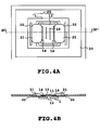
- Fig. 4A is a plan view for a brief explanation of a main part of a liquid-ejecting head of the present embodiment, while Fig. 4B is a cross sectional view along the line IV-IV' of Fig. 4A.
- a liquid-ejecting head of the present embodiment has a second depression region in an exterior wiring portion 2 to restrict the range of sealing resin 21.
- the liquid-ejecting head is manufactured by the following steps.
- a first step is to prepare an ejection element portion 20 by the same way as that of Embodiment 1.
- a groove is formed as a depression region 22 in a base film of a sealing region of TAB to prepare the TAB of the present embodiment. That is, the groove of 0.3 mm in width is provided as the depression region is 1.0 mm away from the ejection port 10 toward the device hole of the TAB.
- a thickness of the base plate is 75 ⁇ m and a depth of the depression region is 75 ⁇ m.
- a flow of the sealing resin 21 is stopped at an edge of the depression region 22 by a surface tension of the resin with a high accuracy, permitting a larger cap region 23 and smaller sized TAB.
- the formation of device hole and the formation of depression region can be performed at the same time, so that there is no need to provide an additional step and to pay an additional manufacturing cost.
- the range of the sealing resin can be restricted as described above, the miniaturization of the base plate has allowed in addition to pave the road to avoid the possibility of blocking the ejection orifices by the sealing resin and to avoid the possibility of poorly shaped sealing resin.
- Fig. 5A is a perspective view for a brief explanation of a main part of a liquid-ejecting head of the present embodiment corresponding to one of Embodiments 1 to 3, while Fig. 5B is a cross sectional view along the line V-V' of Fig. 5A.
- the reference numeral 402 denotes a Si element base plate on which heaters as electrothermal transducer elements and ejection orifices are formed by means of thin-film processing technology.
- a plurality of ejection orifices 4 is arranged as two rows of staggered openings in a surface of the element base plate 402 which is cemented to a part of a supporting member 102 in the shape of "L".
- a wiring base 104 is fixed on the supporting member 102. A wiring portion of the wiring base 104 is electrically connected to a wiring portion of the element base plate 402 by bonding.
- the supporting member 102 is made of an aluminum material.
- a molded member 103 is provided for holding the supporting member 102, so that a part of the latter is inserted into an inside of the former.
- the molded member 103 is provided for 102 for supplying a liquid (such as ink) to a liquid-storing portion (not shown) through a liquid-supplying path 107 formed therein.
- the molded member 103 acts as a placement and positioning member for removably mounting the liquid-ejecting head on a liquid-ejecting head described later.
- An internal portion of the element base plate 402 has a communicating path 105 that passing through the element base plate 402. Also, the communicating path 105 is provided as a common liquid chamber that communicates with each orifice through the liquid flow path.
- the electrically connected portion is positioned in parallel with the direction of an arrangement of a plurality of orifices, so that the depression region is also positioned in parallel with that arrangement.
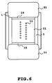
- the relationship between the direction of arranging a plurality of orifices and electrically connected portion of Fig. 3A and 3B is modified as shown in Fig. 6. That is, the electrically connected portion is positioned vertically against the direction of arranging a plurality of orifices, and also the depression region is formed along a line orthogonal to the direction of that arrangement.
- a liquid-ejecting apparatus as one of preferred embodiment of the present invention, on which a liquid-ejecting head of the present invention is removably mounted.
- Fig. 7 is a partially sectional perspective view illustrating a general configuration of the liquid-ejecting apparatus of the present invention.
- the reference numeral 200 denotes a carriage on which the liquid-ejecting head described above is removably mounted.
- four different liquid-ejecting heads are mounted on the carriage so as to correspond to different ink colors and these heads connects to their respective ink tanks which are also mounted on the carriage, including a tank 201Y for yellow ink, a tank 201M for magenta ink, a tank 201C for cyan, and a tank 201B for black ink.
- the carriage 200 is supported by a guide shaft 202 so as to shift its position as a back-and-forth motion along the guide shaft 202 by forwarding or reversing the direction (along the arrow A in the figure) of rotation of an endless belt 204 by a driving force of a motor 203.
- the endless belt 204 passes over pulleys 205 and 206 to transmit motion of the motor 203.
- a sheet of printing paper P is provided as a printing medium and is intermittently transmitted along the direction of arrow B perpendicular to the arrow A.
- the printing paper P is held at two positions by a pair of roller units 207, 208 on the side of upstream and a pair of roller units 209, 210 on the side of downstream, so that it receives a force tending to stretch the paper to keep its plainness against the head during its movement.
- Each roller unit receives a driving force from a driving portion 211. Alternatively, the roller unit may receive a driving force from the motor described above.
- the carriage stops at its home position as necessary during the state of printing or at the time of starting the printing. In this position, there is a cap member for capping an ejection surface of the head.
- the cap member 212 is connected to a suction recovery device (not shown) for preventing the clogging of the orifice by forcefully sucking the ink from the orifices of the ejection surface.
- Fig. 8 is a block diagram illustrating a general view of the liquid-ejecting apparatus for operating the printing procedure with ink ejection in which both the liquid-ejection method and the liquid-ejection head of the present invention are applied.
- the printing apparatus receives a printing information from a host computer 300 as a control signal.
- the printing information is temporarily stored in an input interface 301 in the printing apparatus, and in conjunction therewith, converted into data to be process in the printing apparatus and then input to a CPU 302 which, in turn, serves as head driving signal supply means.
- the CPU processes the input data using RAM 304 and other peripheral units on the basis of the control program stored in a ROM 303 to convert into the printing data (image data).
- the CPU 302 generates a drive data for driving the driving motor for shifting the printing medium and the printing head in synchronism with the image data so that the image data may be printed at appropriate position on the printing medium.
- the driving data and the motor driving data are transmitted to respective of head 200 and the driving motor 306 via a head driver 307 and a motor driver 305 for driving them at respective controlled timing to form the image.
- the printing medium applicable for the printing apparatus set forth above and to deposit the liquid such as the ink, various paper, OH sheet, plastic material to be employed for a compact disk, decorative panel or the like, cloth, metal materials, such as aluminum, copper or the like, leathers, such as cattle hide, lyophilized porcine skin, simulated synthetic leather substitute, lumber, such as wood, plywood, bamboo, ceramic material, such as tile, three-dimensional structural body, such as sponge or the like, may be used.
- the printing apparatus described above may be selected from a printing apparatus for printing on various paper, OH sheet, and the like; a plastic-printing apparatus for printing on a plastic material to be employed for a compact disk, decorative panel or the like; a textile printing apparatus for printing on cloth; a metal-printing apparatus for printing on a metal material; a leather printing apparatus for printing on a leather; lumber-printing apparatus for printing on a lumber; ceramic-printing apparatus for printing on a ceramic material; and a receding apparatus for printing on a three-dimensional structural body.
- the ejection liquid to be used in these liquid ejecting apparatus the liquid adapted to respective printing medium or printing condition may be used.
- Fig. 9 is a diagrammatic illustration for explaining the construction of the ink-jet printing system employing the foregoing liquid ejection head 201 according to the present invention.
- the liquid ejecting head is a full-line type head, in which a plurality of ejection ports at interval of 360 dpi in a length corresponding to a printable width of the printing medium 150, in which four heads respectively corresponding to four colors of yellow (Y), magenta (M), cyan (C) and black (Bk) are fixedly supported in parallel relationship with a given interval in X direction by means of a head holder 202.
- signal is supplied from the head driver 307 forming respective driving signal supply means. On the basis of this signal, respective head is driven.
- ink containers 204a to 204d For respective heads, four colors of inks of Y, M, C and Bk as ejection liquids are supplied from ink containers 204a to 204d,
- the reference numeral 204e denotes a bubbling liquid container storing the bubbling liquid. From this container, bubbling liquid is supplied to each head.
- head caps 203a to 203d in which ink absorbing member, such as sponge or so forth is arranged are provided for maintenance of the head by covering the ejection ports of respective heads during non-printing.
- the reference numeral 206 denotes a transporting belt forming the transporting means for transporting the various printing mediums.
- the transporting belt 206 runs across a predetermined path defined by various rollers, and is driven by the driving motor connected to the motor driver 305.
- a pre-treatment device 251 and a post-treatment device 252 for performing various processes for the printing medium are provided upstream and downstream of the printing medium transporting path.
- Content of the pre-treatment and the post-treatment are differentiated depending upon kind of the printing medium and kind of the ink.
- irradiation of ultraviolet and ozone is performed by pre-treatment to improve adhesion ability of the ink by making the surface active.
- the printing medium such as plastic
- dust can easily deposit on the surface of the printing medium thereby to obstruct high quality printing.
- static electricity of the printing medium is removed by ionizer device and whereby dust is removed from the printing medium.
- a material selected from alkaline material, water soluble material, synthetic high polymer, water soluble metal salt, urea and thiourea may be applied to the cloth for pre-treatment.
- the pre-treatment is not limited to these treatments but can be the treatment for adjusting the temperature of the printing medium to the appropriate temperature.
- the post-treatment may be a heat-treatment for the printing medium, for which the ink is applied, a fixing treatment for promoting fixing of the ink by irradiation of ultraviolet ray or the like, treatment for washing the treatment liquid applied in the pre-treatment and left non-reacted.
- the full-line head is employed as the head in the present embodiment.
- the printing head to be employed is not limited to the full-line head but can be in a form where a small size head is shifted in the width direction of the printing medium.
- a liquid-ejecting apparatus of the present invention is for ejecting a liquid on a printing medium to print.
- the apparatus has a carriage that moves along a main-scanning direction, on which a liquid-ejecting head (200) for ejecting the liquid is removably mounted as a removable head or is fixed as a stationary head, a transporting device for transporting the printing medium, a control device for controlling movements of the liquid-ejecting head, the carriage, and the transporting device.
- the liquid-ejecting head (200) has an ejection element portion (20) that includes an energy-generating device for ejecting a liquid, a plurality of ejection orifices (10) positioned in a direction perpendicular to the energy-generating device, and a wiring device for sending an electrical signal to the energy-generating device, an exterior wiring portion (2) for applying the electric signal to the wiring device of the ejection element portion (20), an electrically connected portion where the wiring device and the exterior wiring portion (2) are electrically connected together, and a sealing resin portion (21) that seals the electrically connected portion.
- a depression region (14) is formed so as to be positioned between the plurality of orifices (10) and one end portion of the sealing resin portion (21) positioned between the plurality of orifices (10) and the electrically connected portion.
- the depression region (14) limits a position of the one end portion of the sealing resin portion (21).
Landscapes
- Engineering & Computer Science (AREA)
- Manufacturing & Machinery (AREA)
- Particle Formation And Scattering Control In Inkjet Printers (AREA)
- Ink Jet (AREA)
Applications Claiming Priority (3)
| Application Number | Priority Date | Filing Date | Title |
|---|---|---|---|
| JP8202447A JPH1044419A (ja) | 1996-07-31 | 1996-07-31 | 液体吐出ヘッド、液体吐出ヘッドの製造方法、液体吐出装置、および記録装置 |
| JP20244796 | 1996-07-31 | ||
| JP202447/96 | 1996-07-31 |
Publications (3)
| Publication Number | Publication Date |
|---|---|
| EP0822077A2 true EP0822077A2 (fr) | 1998-02-04 |
| EP0822077A3 EP0822077A3 (fr) | 1998-09-23 |
| EP0822077B1 EP0822077B1 (fr) | 2004-12-22 |
Family
ID=16457682
Family Applications (1)
| Application Number | Title | Priority Date | Filing Date |
|---|---|---|---|
| EP97113006A Expired - Lifetime EP0822077B1 (fr) | 1996-07-31 | 1997-07-29 | Tête d'éjection de liquide et procédé de sa fabrication |
Country Status (4)
| Country | Link |
|---|---|
| US (1) | US6099109A (fr) |
| EP (1) | EP0822077B1 (fr) |
| JP (1) | JPH1044419A (fr) |
| DE (1) | DE69732001T2 (fr) |
Cited By (3)
| Publication number | Priority date | Publication date | Assignee | Title |
|---|---|---|---|---|
| EP1098767A4 (fr) * | 1998-05-14 | 2001-10-10 | Lexmark Int Inc | Fabrication d'une tete d'impression thermique |
| US6325488B1 (en) | 1997-10-28 | 2001-12-04 | Hewlett-Packard Company | Inkjet printhead for wide area printing |
| WO2019211070A1 (fr) * | 2018-05-03 | 2019-11-07 | Memjet Technology Limited | Tête d'impression à jet d'encre comportant des caractéristiques de retenue d'encapsulant |
Families Citing this family (17)
| Publication number | Priority date | Publication date | Assignee | Title |
|---|---|---|---|---|
| DE60003767T2 (de) * | 1999-10-29 | 2004-06-03 | Hewlett-Packard Co. (N.D.Ges.D.Staates Delaware), Palo Alto | Tintenstrahldruckkopf mit verbesserter Zuverlässigkeit |
| JP4632386B2 (ja) * | 2000-12-21 | 2011-02-16 | キヤノン株式会社 | 液体吐出記録ヘッド |
| US6520624B1 (en) * | 2002-06-18 | 2003-02-18 | Hewlett-Packard Company | Substrate with fluid passage supports |
| JP4332416B2 (ja) * | 2003-12-12 | 2009-09-16 | キヤノン株式会社 | インクジェット記録ヘッド |
| DE102004004422A1 (de) * | 2004-01-29 | 2005-08-18 | Conti Temic Microelectronic Gmbh | Elektronisches Gerät sowie Verfahren zum Bonden eines elektronischen Gerätes |
| JP5038090B2 (ja) * | 2006-12-21 | 2012-10-03 | キヤノン株式会社 | 液体吐出ヘッド |
| US20080158298A1 (en) * | 2006-12-28 | 2008-07-03 | Serbicki Jeffrey P | Printhead wirebond encapsulation |
| JP2010000632A (ja) * | 2008-06-18 | 2010-01-07 | Canon Inc | インクジェットヘッド用基板および該基板を具えるインクジェットヘッド |
| JP5455575B2 (ja) | 2009-11-17 | 2014-03-26 | キヤノン株式会社 | 記録装置 |
| JP5528071B2 (ja) * | 2009-11-25 | 2014-06-25 | キヤノン株式会社 | 液体噴射記録ヘッドおよび液体噴射記録ヘッドの製造方法 |
| JP5665366B2 (ja) * | 2010-05-17 | 2015-02-04 | キヤノン株式会社 | 記録装置 |
| JP6537312B2 (ja) * | 2014-05-12 | 2019-07-03 | キヤノン株式会社 | 液体吐出ヘッドとその製造方法及び液体吐出装置 |
| JP6604740B2 (ja) * | 2014-05-30 | 2019-11-13 | キヤノン株式会社 | 半導体基板および液体吐出ヘッド用基板の作製方法 |
| PL3095613T3 (pl) * | 2015-05-22 | 2020-06-01 | Agfa Nv | Wytwarzanie paneli dekoracyjnych metodą druku natryskowego |
| JP2016221777A (ja) * | 2015-05-28 | 2016-12-28 | セイコーエプソン株式会社 | 液体噴射ヘッドユニット、液体噴射装置及びワイピング方法 |
| US10438864B2 (en) * | 2015-08-21 | 2019-10-08 | Hewlett-Packard Development Company, L.P. | Circuit packages comprising epoxy mold compounds and methods of compression molding |
| JP7146532B2 (ja) * | 2018-09-05 | 2022-10-04 | キヤノン株式会社 | 液体吐出ヘッドとその製造方法 |
Family Cites Families (18)
| Publication number | Priority date | Publication date | Assignee | Title |
|---|---|---|---|---|
| JPS5527282A (en) * | 1978-08-18 | 1980-02-27 | Canon Inc | Liquid injection recording method and its device |
| JPS5459936A (en) * | 1977-10-03 | 1979-05-15 | Canon Inc | Recording method and device therefor |
| CA1127227A (fr) * | 1977-10-03 | 1982-07-06 | Ichiro Endo | Procede d'enregistrement a jet liquide et appareil d'enregistrement |
| US4881318A (en) * | 1984-06-11 | 1989-11-21 | Canon Kabushiki Kaisha | Method of manufacturing a liquid jet recording head |
| JPH064325B2 (ja) * | 1984-06-11 | 1994-01-19 | キヤノン株式会社 | 液体噴射ヘッド |
| JPH0822594B2 (ja) * | 1984-10-19 | 1996-03-06 | キヤノン株式会社 | インクジェット記録ヘッド |
| US4860033A (en) * | 1987-02-04 | 1989-08-22 | Canon Kabushiki Kaisha | Base plate having an oxidation film and an insulating film for ink jet recording head and ink jet recording head using said base plate |
| JPH0216549A (ja) * | 1988-07-05 | 1990-01-19 | Brother Ind Ltd | 画像形成装置 |
| JPH04175728A (ja) * | 1990-11-08 | 1992-06-23 | Minolta Camera Co Ltd | 固体走査型光プリントヘッド |
| EP0490668B1 (fr) * | 1990-12-12 | 1996-10-16 | Canon Kabushiki Kaisha | Enregistrement par jet d'encre |
| US5479197A (en) * | 1991-07-11 | 1995-12-26 | Canon Kabushiki Kaisha | Head for recording apparatus |
| EP0525787B1 (fr) * | 1991-08-01 | 1996-10-16 | Canon Kabushiki Kaisha | Méthode pour la fabrication d'une tête d'enregistrement |
| EP0585854B1 (fr) * | 1992-08-31 | 1998-11-11 | Canon Kabushiki Kaisha | Méthode pour la production d'une tête à encre à façonnage par ions et tête à jet d'encre |
| JP3115720B2 (ja) * | 1992-09-29 | 2000-12-11 | キヤノン株式会社 | インクジェット記録ヘッド、該記録ヘッドを備えたインクジェット記録装置及び該記録ヘッドの製造方法 |
| US5343230A (en) * | 1992-11-20 | 1994-08-30 | Xerox Corporation | Electrical interconnect actuation which interacts with cap station articulation |
| US5519421A (en) * | 1994-07-18 | 1996-05-21 | Hewlett-Packard Company | Disruption of polymer surface of a nozzle member to inhibit adhesive flow |
| US5896153A (en) * | 1994-10-04 | 1999-04-20 | Hewlett-Packard Company | Leak resistant two-material frame for ink-jet print cartridge |
| JP3459726B2 (ja) * | 1996-06-14 | 2003-10-27 | キヤノン株式会社 | インクジェット記録ヘッド及びその製造方法 |
-
1996
- 1996-07-31 JP JP8202447A patent/JPH1044419A/ja active Pending
-
1997
- 1997-07-29 US US08/902,325 patent/US6099109A/en not_active Expired - Lifetime
- 1997-07-29 DE DE69732001T patent/DE69732001T2/de not_active Expired - Lifetime
- 1997-07-29 EP EP97113006A patent/EP0822077B1/fr not_active Expired - Lifetime
Cited By (6)
| Publication number | Priority date | Publication date | Assignee | Title |
|---|---|---|---|---|
| US6325488B1 (en) | 1997-10-28 | 2001-12-04 | Hewlett-Packard Company | Inkjet printhead for wide area printing |
| US6513907B2 (en) | 1997-10-28 | 2003-02-04 | Hewlett-Packard Company | Inkjet printhead for wide area printing |
| EP1098767A4 (fr) * | 1998-05-14 | 2001-10-10 | Lexmark Int Inc | Fabrication d'une tete d'impression thermique |
| WO2019211070A1 (fr) * | 2018-05-03 | 2019-11-07 | Memjet Technology Limited | Tête d'impression à jet d'encre comportant des caractéristiques de retenue d'encapsulant |
| US10850517B2 (en) | 2018-05-03 | 2020-12-01 | Memjet Technology Limited | Inkjet printhead with grout retaining features |
| US10864733B2 (en) | 2018-05-03 | 2020-12-15 | Memjet Technology Limited | Inkjet printhead with encapsulant-retaining features |
Also Published As
| Publication number | Publication date |
|---|---|
| JPH1044419A (ja) | 1998-02-17 |
| US6099109A (en) | 2000-08-08 |
| DE69732001D1 (de) | 2005-01-27 |
| EP0822077A3 (fr) | 1998-09-23 |
| EP0822077B1 (fr) | 2004-12-22 |
| DE69732001T2 (de) | 2005-12-15 |
Similar Documents
| Publication | Publication Date | Title |
|---|---|---|
| US6099109A (en) | Liquid-ejecting head and method of manufacturing the same | |
| US8517509B2 (en) | Liquid ejection head and image-forming apparatus using the same | |
| EP0822081B1 (fr) | Tête à éjection de liquide, cartouche de tête à éjection, appareil d'impression, système d'impression et procédé de fabrication de tête à éjection | |
| US6270199B1 (en) | Liquid ejecting head, liquid ejecting device and liquid ejecting method | |
| EP1057646A2 (fr) | Formation d'images en encre contenant un film de protection | |
| EP1228876B1 (fr) | Tête d'ejection de liquide, procede de remise en état par suction, cartouche de tête et appareil de formation d'images | |
| US6231156B1 (en) | Ink-jet printing apparatus and ejection recovery method of printing head | |
| US20020109746A1 (en) | Liquid ejection apparatus head unit and ink-jet cartridge | |
| JP3667096B2 (ja) | インクジェット記録装置及びインクジェット記録方法 | |
| JP3320317B2 (ja) | インクジェットプリント装置およびプリント方法 | |
| JPH1199651A (ja) | 液体吐出方法及び液体吐出装置 | |
| JP3554099B2 (ja) | インクジェットプリント装置 | |
| EP0847872A1 (fr) | Méthode pour l'impression par jet d'encre utilisant un premier et un deuxième liquide, et un appareil pour cette méthode | |
| US6179412B1 (en) | Liquid discharging head, having opposed element boards and grooved member therebetween | |
| JP3554113B2 (ja) | 液体吐出ヘッド、液体吐出ヘッドの製造方法、液体吐出装置、および記録システム | |
| EP0819535B1 (fr) | Procédé et appareil d'impression par jet d'encre pour textile | |
| JPH08336979A (ja) | カラーインクジェット記録装置及びその記録方法 | |
| US6848769B2 (en) | Liquid ejecting head having a plurality of groups of ejection openings, and image-forming device using the same | |
| US6132031A (en) | Ink-jet head, ink-jet cartridge and ink-jet printing apparatus | |
| EP1633566B1 (fr) | Dispositif de pulverisation de jet multifluide ameliore | |
| JP3728253B2 (ja) | 液体吐出ヘッドおよび画像形成装置 | |
| JPH11188862A (ja) | インクジェット記録装置およびインクジェット記録方法 | |
| US20090153624A1 (en) | Liquid ejection head and printing apparatus | |
| JP3639698B2 (ja) | 液体吐出ヘッド、ヘッドカートリッジ、液体吐出記録装置、および液体吐出ヘッドの製造方法 | |
| JPH054335A (ja) | 記録装置 |
Legal Events
| Date | Code | Title | Description |
|---|---|---|---|
| PUAI | Public reference made under article 153(3) epc to a published international application that has entered the european phase |
Free format text: ORIGINAL CODE: 0009012 |
|
| AK | Designated contracting states |
Kind code of ref document: A2 Designated state(s): DE FR GB IT |
|
| AX | Request for extension of the european patent |
Free format text: AL;LT;LV;RO;SI |
|
| PUAL | Search report despatched |
Free format text: ORIGINAL CODE: 0009013 |
|
| AK | Designated contracting states |
Kind code of ref document: A3 Designated state(s): AT BE CH DE DK ES FI FR GB GR IE IT LI LU MC NL PT SE |
|
| AX | Request for extension of the european patent |
Free format text: AL;LT;LV;RO;SI |
|
| 17P | Request for examination filed |
Effective date: 19990208 |
|
| AKX | Designation fees paid |
Free format text: DE FR GB IT |
|
| RBV | Designated contracting states (corrected) |
Designated state(s): DE FR GB IT |
|
| 17Q | First examination report despatched |
Effective date: 20010206 |
|
| GRAP | Despatch of communication of intention to grant a patent |
Free format text: ORIGINAL CODE: EPIDOSNIGR1 |
|
| GRAS | Grant fee paid |
Free format text: ORIGINAL CODE: EPIDOSNIGR3 |
|
| GRAA | (expected) grant |
Free format text: ORIGINAL CODE: 0009210 |
|
| AK | Designated contracting states |
Kind code of ref document: B1 Designated state(s): DE FR GB IT |
|
| PG25 | Lapsed in a contracting state [announced via postgrant information from national office to epo] |
Ref country code: IT Free format text: LAPSE BECAUSE OF FAILURE TO SUBMIT A TRANSLATION OF THE DESCRIPTION OR TO PAY THE FEE WITHIN THE PRESCRIBED TIME-LIMIT;WARNING: LAPSES OF ITALIAN PATENTS WITH EFFECTIVE DATE BEFORE 2007 MAY HAVE OCCURRED AT ANY TIME BEFORE 2007. THE CORRECT EFFECTIVE DATE MAY BE DIFFERENT FROM THE ONE RECORDED. Effective date: 20041222 Ref country code: FR Free format text: LAPSE BECAUSE OF FAILURE TO SUBMIT A TRANSLATION OF THE DESCRIPTION OR TO PAY THE FEE WITHIN THE PRESCRIBED TIME-LIMIT Effective date: 20041222 |
|
| REG | Reference to a national code |
Ref country code: GB Ref legal event code: FG4D |
|
| REF | Corresponds to: |
Ref document number: 69732001 Country of ref document: DE Date of ref document: 20050127 Kind code of ref document: P |
|
| PLBE | No opposition filed within time limit |
Free format text: ORIGINAL CODE: 0009261 |
|
| STAA | Information on the status of an ep patent application or granted ep patent |
Free format text: STATUS: NO OPPOSITION FILED WITHIN TIME LIMIT |
|
| 26N | No opposition filed |
Effective date: 20050923 |
|
| EN | Fr: translation not filed | ||
| PGFP | Annual fee paid to national office [announced via postgrant information from national office to epo] |
Ref country code: DE Payment date: 20140731 Year of fee payment: 18 |
|
| PGFP | Annual fee paid to national office [announced via postgrant information from national office to epo] |
Ref country code: GB Payment date: 20140724 Year of fee payment: 18 |
|
| REG | Reference to a national code |
Ref country code: DE Ref legal event code: R119 Ref document number: 69732001 Country of ref document: DE |
|
| GBPC | Gb: european patent ceased through non-payment of renewal fee |
Effective date: 20150729 |
|
| PG25 | Lapsed in a contracting state [announced via postgrant information from national office to epo] |
Ref country code: GB Free format text: LAPSE BECAUSE OF NON-PAYMENT OF DUE FEES Effective date: 20150729 Ref country code: DE Free format text: LAPSE BECAUSE OF NON-PAYMENT OF DUE FEES Effective date: 20160202 |