EP0822081A2 - Flüssigkeitsausstosskopf, Flüssigkeitsausstosskopfkartusche, Druckapparat, Drucksystem und Herstellungsverfahren für einen Flüssigkeitsausstosskopf - Google Patents
Flüssigkeitsausstosskopf, Flüssigkeitsausstosskopfkartusche, Druckapparat, Drucksystem und Herstellungsverfahren für einen Flüssigkeitsausstosskopf Download PDFInfo
- Publication number
- EP0822081A2 EP0822081A2 EP97113149A EP97113149A EP0822081A2 EP 0822081 A2 EP0822081 A2 EP 0822081A2 EP 97113149 A EP97113149 A EP 97113149A EP 97113149 A EP97113149 A EP 97113149A EP 0822081 A2 EP0822081 A2 EP 0822081A2
- Authority
- EP
- European Patent Office
- Prior art keywords
- liquid
- head
- chip
- equal
- installation hole
- Prior art date
- Legal status (The legal status is an assumption and is not a legal conclusion. Google has not performed a legal analysis and makes no representation as to the accuracy of the status listed.)
- Granted
Links
Images






Classifications
-
- B—PERFORMING OPERATIONS; TRANSPORTING
- B41—PRINTING; LINING MACHINES; TYPEWRITERS; STAMPS
- B41J—TYPEWRITERS; SELECTIVE PRINTING MECHANISMS, i.e. MECHANISMS PRINTING OTHERWISE THAN FROM A FORME; CORRECTION OF TYPOGRAPHICAL ERRORS
- B41J2/00—Typewriters or selective printing mechanisms characterised by the printing or marking process for which they are designed
- B41J2/005—Typewriters or selective printing mechanisms characterised by the printing or marking process for which they are designed characterised by bringing liquid or particles selectively into contact with a printing material
- B41J2/01—Ink jet
- B41J2/135—Nozzles
- B41J2/14—Structure thereof only for on-demand ink jet heads
- B41J2/14016—Structure of bubble jet print heads
- B41J2/14072—Electrical connections, e.g. details on electrodes, connecting the chip to the outside...
-
- B—PERFORMING OPERATIONS; TRANSPORTING
- B41—PRINTING; LINING MACHINES; TYPEWRITERS; STAMPS
- B41J—TYPEWRITERS; SELECTIVE PRINTING MECHANISMS, i.e. MECHANISMS PRINTING OTHERWISE THAN FROM A FORME; CORRECTION OF TYPOGRAPHICAL ERRORS
- B41J2/00—Typewriters or selective printing mechanisms characterised by the printing or marking process for which they are designed
- B41J2/005—Typewriters or selective printing mechanisms characterised by the printing or marking process for which they are designed characterised by bringing liquid or particles selectively into contact with a printing material
- B41J2/01—Ink jet
- B41J2/135—Nozzles
- B41J2/14—Structure thereof only for on-demand ink jet heads
- B41J2/14016—Structure of bubble jet print heads
- B41J2/14024—Assembling head parts
-
- B—PERFORMING OPERATIONS; TRANSPORTING
- B41—PRINTING; LINING MACHINES; TYPEWRITERS; STAMPS
- B41J—TYPEWRITERS; SELECTIVE PRINTING MECHANISMS, i.e. MECHANISMS PRINTING OTHERWISE THAN FROM A FORME; CORRECTION OF TYPOGRAPHICAL ERRORS
- B41J2/00—Typewriters or selective printing mechanisms characterised by the printing or marking process for which they are designed
- B41J2/005—Typewriters or selective printing mechanisms characterised by the printing or marking process for which they are designed characterised by bringing liquid or particles selectively into contact with a printing material
- B41J2/01—Ink jet
- B41J2/135—Nozzles
- B41J2/16—Production of nozzles
- B41J2/1601—Production of bubble jet print heads
- B41J2/1603—Production of bubble jet print heads of the front shooter type
-
- B—PERFORMING OPERATIONS; TRANSPORTING
- B41—PRINTING; LINING MACHINES; TYPEWRITERS; STAMPS
- B41J—TYPEWRITERS; SELECTIVE PRINTING MECHANISMS, i.e. MECHANISMS PRINTING OTHERWISE THAN FROM A FORME; CORRECTION OF TYPOGRAPHICAL ERRORS
- B41J2/00—Typewriters or selective printing mechanisms characterised by the printing or marking process for which they are designed
- B41J2/005—Typewriters or selective printing mechanisms characterised by the printing or marking process for which they are designed characterised by bringing liquid or particles selectively into contact with a printing material
- B41J2/01—Ink jet
- B41J2/135—Nozzles
- B41J2/16—Production of nozzles
- B41J2/1621—Manufacturing processes
- B41J2/1623—Manufacturing processes bonding and adhesion
-
- B—PERFORMING OPERATIONS; TRANSPORTING
- B41—PRINTING; LINING MACHINES; TYPEWRITERS; STAMPS
- B41J—TYPEWRITERS; SELECTIVE PRINTING MECHANISMS, i.e. MECHANISMS PRINTING OTHERWISE THAN FROM A FORME; CORRECTION OF TYPOGRAPHICAL ERRORS
- B41J2/00—Typewriters or selective printing mechanisms characterised by the printing or marking process for which they are designed
- B41J2/005—Typewriters or selective printing mechanisms characterised by the printing or marking process for which they are designed characterised by bringing liquid or particles selectively into contact with a printing material
- B41J2/01—Ink jet
- B41J2/135—Nozzles
- B41J2/16—Production of nozzles
- B41J2/1621—Manufacturing processes
- B41J2/1625—Manufacturing processes electroforming
-
- B—PERFORMING OPERATIONS; TRANSPORTING
- B41—PRINTING; LINING MACHINES; TYPEWRITERS; STAMPS
- B41J—TYPEWRITERS; SELECTIVE PRINTING MECHANISMS, i.e. MECHANISMS PRINTING OTHERWISE THAN FROM A FORME; CORRECTION OF TYPOGRAPHICAL ERRORS
- B41J2/00—Typewriters or selective printing mechanisms characterised by the printing or marking process for which they are designed
- B41J2/005—Typewriters or selective printing mechanisms characterised by the printing or marking process for which they are designed characterised by bringing liquid or particles selectively into contact with a printing material
- B41J2/01—Ink jet
- B41J2/135—Nozzles
- B41J2/16—Production of nozzles
- B41J2/1621—Manufacturing processes
- B41J2/1631—Manufacturing processes photolithography
-
- B—PERFORMING OPERATIONS; TRANSPORTING
- B41—PRINTING; LINING MACHINES; TYPEWRITERS; STAMPS
- B41J—TYPEWRITERS; SELECTIVE PRINTING MECHANISMS, i.e. MECHANISMS PRINTING OTHERWISE THAN FROM A FORME; CORRECTION OF TYPOGRAPHICAL ERRORS
- B41J2/00—Typewriters or selective printing mechanisms characterised by the printing or marking process for which they are designed
- B41J2/005—Typewriters or selective printing mechanisms characterised by the printing or marking process for which they are designed characterised by bringing liquid or particles selectively into contact with a printing material
- B41J2/01—Ink jet
- B41J2/135—Nozzles
- B41J2/16—Production of nozzles
- B41J2/1621—Manufacturing processes
- B41J2/1632—Manufacturing processes machining
-
- B—PERFORMING OPERATIONS; TRANSPORTING
- B41—PRINTING; LINING MACHINES; TYPEWRITERS; STAMPS
- B41J—TYPEWRITERS; SELECTIVE PRINTING MECHANISMS, i.e. MECHANISMS PRINTING OTHERWISE THAN FROM A FORME; CORRECTION OF TYPOGRAPHICAL ERRORS
- B41J2/00—Typewriters or selective printing mechanisms characterised by the printing or marking process for which they are designed
- B41J2/005—Typewriters or selective printing mechanisms characterised by the printing or marking process for which they are designed characterised by bringing liquid or particles selectively into contact with a printing material
- B41J2/01—Ink jet
- B41J2/135—Nozzles
- B41J2/16—Production of nozzles
- B41J2/1621—Manufacturing processes
- B41J2/1637—Manufacturing processes molding
-
- B—PERFORMING OPERATIONS; TRANSPORTING
- B41—PRINTING; LINING MACHINES; TYPEWRITERS; STAMPS
- B41J—TYPEWRITERS; SELECTIVE PRINTING MECHANISMS, i.e. MECHANISMS PRINTING OTHERWISE THAN FROM A FORME; CORRECTION OF TYPOGRAPHICAL ERRORS
- B41J2202/00—Embodiments of or processes related to ink-jet or thermal heads
- B41J2202/01—Embodiments of or processes related to ink-jet heads
- B41J2202/21—Line printing
Definitions
- the present invention relates to a liquid ejection head, a liquid ejection head cartridge incorporating the liquid ejection head, a printing apparatus employing the liquid ejection head cartridge, a printing system employing the printing apparatus, and a fabrication process of the liquid ejection head.
- a printing apparatus such as an ink-jet printer, has a liquid ejection head, i.e. an ink-jet head including an ejection energy generating means for heating a liquid in a liquid passage and whereby ejecting the liquid from an ejection opening.
- the ink-jet head is a major portion constructed with a head chip having a liquid chamber, to which the liquid is supplied, and an electric wiring substrate, to which the head chip is connected.
- an electrical wiring for applying an electrical pulse to an electrothermal transducer as the ejection energy generating means for heating the liquid in each liquid passage is built-in.
- the head chip in which an IC is built-in, or in which wiring corresponded to the electrothermal transducer are provided in one-by-one basis and an IC is mounted on the electrical wiring substrate side.
- the head chip of the ink-jet head and the electrical wiring substrate are assembled, it has been typically employed, in the prior art, to connect the head chip to a print circuit board as the electric wiring substrate by wire bonding, or to fit a predetermined mating surface of the head chip onto a flexible print circuit board as the electric wiring substrate under pressure.
- TAB tape automated bonding
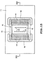
- FIG. 15 A configuration in plan view of the ink-jet head produced by the TAB system is illustrated in Fig. 15, and a section taken along line XVI - XVI is shown in Fig. 16, and a configuration in plan view of the condition where the head chip and the electric wiring substrate are connected but a seal resin is not yet applied, is illustrated in Fig. 17.
- a chip installation hole 13 At a center portion of an electrically insulative film form electric wiring substrate 11, a chip installation hole 13 having the same corresponding to an outer contour of a head chip 12 is formed.
- a plurality of lead terminals 14 having tip ends to be fitted on the head chip 12 are projected from the inner periphery of the chip installation hole 11.
- connection electrodes exposed on the surface of the head chip 12 are mated with each other for establishing electrical connection therebetween.
- a seal resin 16 is applied over the chip head 12 and the electrical wiring substrate 11 so as to seal the connecting portion.
- ejection openings 15 for the liquid are arranged at the center portion of the head chip 12. Therefore, the seal resin 16 has to be applied without blocking these ejection openings 15.
- the seal resin 16 cannot be applied for the portion where the lead terminals 14 are not projected from the inner periphery of the chip installation hole 13. If attempt is made to apply the seal resin 16 between the head chip 12 and the chip installation hole 13 over the entire circumference of the head chip 12, the seal resin 16 should penetrate into the back side of the electric wiring substrate 11 through a gap portion S where the lead terminal 14 is not present to make it impossible to maintain the ink-jet head in normal configuration. Furthermore, since there is a portion where the seal resin 16 cannot be placed between the electric wiring substrate 11 and the head chip 12, sufficiently high strength in connection cannot be provided.
- the resin should form meniscus should be formed at the end of the gap portion S to prevent the resin from being injected smoothly. This causes a part of the liquid ejected from the ejection opening 15 to penetrate into the end portion of the gap portion S to cause corrosion on the TAB lead for forming electrical wiring of the head chip 12 to cause failure, such as breakage of the circuit and the like.
- the second object of the present invention is to provide a liquid ejection head cartridge employing the liquid ejection head.
- the third object of the present invention is to provide a printing apparatus, in which the liquid ejection head having high strength at a connecting portion between a head chip and an electrical wiring substrate, and can provide high sealing ability, is employed.
- the fourth object of the present invention is to provide a printing system employing the printing apparatus.
- the fifth object of the present invention is to provide a fabrication process of the liquid ejection head.
- a liquid ejection head comprising:
- the ejection opening may be arranged in opposition to the ejection energy generating means.
- the ejection energy generating means may be an electrothermal transducer having a heating resistor generating a heat when an electric signal is applied.
- a liquid ejection head cartridge including a liquid ejection head and a liquid tank storing a liquid for supplying to the liquid ejection head, comprising:
- the liquid may be an ink and/or a treatment liquid for adjusting property of the ink ejected to the printing medium.
- the ejection opening may be arranged in opposition to the ejection energy generating means.
- a printing apparatus comprising:
- the liquid may be an ink and/or a treatment liquid for adjusting property of the ink ejected to the printing medium.
- the mounting portion of the liquid ejection head may be a carriage movable for scanning in a direction perpendicular to a transporting direction of the printing medium which a liquid droplet is ejected from the liquid ejection head.
- the liquid ejection head may be detachable to the carriage.
- the ejection openings of the liquid ejection head may be arranged over the entire width of the printing region of the printing medium.
- Printing may be performed as taking paper, cloth, plastic, metal, wood or leather as the printing medium.
- a plurality of colors of liquids may be ejected from the liquid ejection head to perform color printing by depositing a plurality of colors of liquids in the printing medium.
- a printing system including a control portion for processing an input image information and output means for outputting information processed by the control portion, wherein
- a fabrication process of a liquid ejection head comprising:
- the resin catching portion may be a dummy lead terminal formed on the electric wiring substrate.
- the resin catching portion may be formed by setting the width of the chip installation hole along the aligning direction of the plurality of lead terminals in the connecting portion, to be narrower than other portion.
- the sealing material may be constructed by a solventless epoxy resin.
- the width of the gap between the resin catching portion and the lead terminal closest to the resin catching portion, the width of the gap between the resin catching portion and the head chip, or a width of a gap between the resin catching portion and the inner periphery of the chip installation hole is greater than or equal to 0.05 mm and less than or equal to 0.5 mm, and preferably greater than or equal to 0.1 mm and less than or equal to 0.3 mm.
- the width of the chip installation hole along the aligning direction of the plurality of lead terminals other than the connecting portion may be greater than or equal to 0.7 mm and less than or equal to 2.0 mm, and more preferably to be greater than or equal to 0.8 mm and less than or equal to 1.5 mm.
- the seal resin catching portion for receiving the sealing material layer is formed in the gap portion between the head chip and the chip installation hole, when the seal resin is applied to the gap portion between the head chip and the chip installation hole, the seal resin may not flow around the back surface of the electric wiring substrate to certainly seal the gap between the head chip and the chip installation hole.
- a liquid ejection head according to the present invention will be explained in detail with reference to Figs. 1 to 5 in terms of a side-shooting type, namely one embodiment applied for an ink-jet head, in which an ejection opening of a liquid is arranged in opposition to an ejection energy generating means.
- the present invention is applicable not only for the side-shooting type ink-jet head but also for an edge-shooting type or a type, in which the ejection opening of the liquid is arranged on the side portion of the ejection energy generating means.
- Fig. 1 which illustrates the configuration in front elevation of one embodiment of an ink-jet head
- Fig. 2 which illustrates a section taken along line II - II
- Fig. 3 which illustrates the internal structure of a head chip, on the center portion of a mold member 17 mounted on an electric wiring substrate 11, a cross-sectionally quadrangular recess portion 18 exposing a part of the upper end surface of an L-shaped support member 29 integrally formed with the mold member 17, is formed.
- a liquid supply passage 19 connected to a not shown supply source of a liquid, such as an ink at one end, is opened at the other end thereof.
- a head chip 12 is disposed and integrated by bonding by a not shown adhesive.
- the head chip 12 is constructed the major portion thereof with an ejection element substrate 21, on which electrothermal transducers 20 as ejection energy generating means are arranged at a predetermined interval, a grooved plate 24 overlappingly mated with the ejection element substrate 21 for defining liquid passages 22 separating respective electrothermal transducers 20 and a common liquid chamber 23 communicated with the liquid passages 22.
- a communication passage 25 for establishing communication between the common liquid chamber 23 and the liquid supply passage 19 is formed.
- electrode terminals connected to respective electrothermal transducers 20 are lead on the surface of the ejection element substrate 21.
- ejection openings 15 respectively opposing to the electrothermal transducers 20 are formed.
- the liquid in the liquid passage 22 surrounding the electrothermal transducer 20 is instantly boiled for ejecting a liquid droplet through the ejection opening 15 by the boiling pressure.
- a chip installation hole 13 surrounding a head chip 12 is formed on the center portion of the electric wiring substrate 11, a chip installation hole 13 surrounding a head chip 12 is formed.
- a plurality of lead terminals 14 to be mated with electrode terminals of the head chip 12 are formed in the condition where tip ends of the lead terminals 14 are extended from the inner periphery of the chip end installation hole 13.
- ILB Inner Lead Bonding
- these lead terminals 14 are electrically connected to the electrode terminals of the head chip 12.
- a TAB connection portion between the electrode terminals and the lead terminals 14 is covered with a seal resin 16.
- the seal resin 16 is formed over the head chip 12 and the electrical wiring substrate 11. In the shown embodiment, a thickness of the seal resin 16 is 0.5 mm.
- upper and lower sides of the lead terminals 14 located at the upper and lower end portions, dummy terminals 26 extending into a gap S defined between head chip 12 and the inner periphery of the chip installation hole 13 are arranged to retain the seal resin 16 together with the lead terminals 14.
- an interval between the lead terminals 14 in the width direction is set to be greater than or equal to 0.05 mm and less than or equal to 0.5 mm, and more preferably greater than or equal to 0.1 mm and less than or equal to 0.3 mm, the seal resin 16 hardly flows to the back side of the electrical wiring substrate 11.
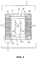
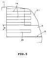
- Fig. 4 illustrating the mating condition of the head chip 12 and the electrical wiring substrate 11 before application of the seal resin 16 and Fig.
- the dummy lead terminals 26 are arranged on the upper and lower sides of the lead terminals 14 located at upper and lower end portions, with projecting into the gap S between the head chip 12 and the chip installation hole 13.
- Intervals W in the width direction between the dummy lead terminals 26 and the adjacent lead terminals 14 and the width of the gap defined between the dummy lead terminals 26 and the inner periphery of the chip installation hole 13 , and the width of the gap between the head chip 12 and the chip installation hole 13 in other portion where the seal resin 16 is applied, are set to be greater than or equal to 0.05 mm and less than or equal to 0.5 mm, and more preferably greater than or equal to 0.1 mm and less than or equal to 0.3 mm (0.1 mm in the shown embodiment). Accordingly, during curing of the seal resin 16, the seal resin 16 may hardly flow to the back side of the electric wiring substrate 11 and whereby can maintain the condition as illustrated in Fig. 1.
- the width of the gap S between the head chip 12 and the chip installation hole 13 in the portion other than the connecting portion along the alignment direction of the lead terminals 14 is set to be greater than or equal to 0.7 mm and less than or equal to 2.0 mm, and more preferably to be greater than or equal to 0.8 mm and less than or equal to 1.5 mm (1.0 mm in the shown embodiment).
- the seal resin 16 employed in the shown embodiment is a solventless epoxy resin (e.g. Chip Coat 8304, available from Hokuriku Toryo Co. which has changed to NAMICS Co.).
- the needle for applying the seal resin 16 is in a range of gauge 18 to 23. However, the kind of the needle may be selected depending upon amount to be applied and application speed.
- a heating resistance layer and an electrode layer are formed on a silicon substrate as the ejection element substrate 21, a heating resistance layer and an electrode layer are formed. Then, by way of photolithography, heating portions (electrothermal transducers 20) are formed. Next, a protective layer is formed. Then, contact hole is formed at a portion to establish electrical connection by photolithography. In the shown embodiment, in order to establish electrical connection with the lead terminals 14 of the electric wiring substrate 11, a metal layer, such as gold layer, is formed. Then, by way of photolithography, electrode terminal is formed. Thus, the ejection element substrate 21 is completed. Subsequently, in order to form the communication passage 25, an aperture is formed through the ejection element substrate 21 by blasting method.
- the liquid passage 22 is formed with a dry film by way of photolithography.
- a grooved plate 24 formed by electroforming is bonded on the ejection element substrate 21, thus formed.
- the head chip 12 thus completed is agglutinated with a support member 29.
- the electric wiring substrate 11 is agglutinated with the mold member 17 so that the lead terminals 14 of the electric wiring substrate 11 overlappingly mate with the electrode terminals of the head chip 12. Thereafter, the lead terminals 14 and the electrode terminals of the head chip 12 are joined by TAB junction.
- the dummy lead terminals 26 is formed in the same configuration as the lead terminal 14.
- the dummy lead terminals 14 may also be formed as projections extending from respective corner portions of the chip installation hole 13.
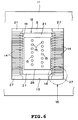
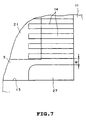
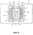
- FIG. 6 Another embodiment of the ink-jet head according to the present invention is illustrated in Fig. 6 showing the connected condition but then seal resin is not yet applied, and in Fig. 7 which shows the portion pointed by the arrow VII in the extracted and enlarged form.
- Fig. 7 shows the portion pointed by the arrow VII in the extracted and enlarged form.
- a distance W between the resin catching portion 27 and the lead terminal 14 located the closest to the resin catching portion 27 is set to be greater than or equal to 0.05 mm and less than or equal to 0.5 mm, and more preferably to be greater than or equal to 0. 1 mm and less than or equal to 0.3 mm (0.1 mm in the shown embodiment).
- the distance between the resin catching portion 27 and the head chip 12 is smaller than the distance W between the resin catching portion 27 and the lead terminal 14 located the closest to the resin catching portion 27, it is desirable to set the distance between the resin catching portion 27 and the head chip 12 within a range of greater than or equal to 0.05 mm and less than or equal to 0.5 mm, and more preferably to be greater than or equal to 0. 1 mm and less than or equal to 0.3 mm.
- the seal resin 16 may not flow to back side of the electrical wiring substrate 11 to maintain the configuration after application.
- the lead terminals 14 are projected from opposing two side edges of the quandrangular chip installation hole 13, and the seal resin 16 is applied along these two side edges, it is possible to apply the seal resin over the entire circumference of the chip installation hole 13.
- the dimension in the width direction of the gap S in the portion where the lead terminal 14 is not formed has to be greater than or equal to 0.05 mm and less than or equal to 0.5 mm, and more preferably to be greater than or equal to 0.1 mm and less than or equal to 0.3 mm.
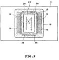
- FIG. 9 A configuration in plan view of another embodiment of the ink-jet head according to the present invention is shown in Fig. 9.
- like elements to those in the former embodiment will be identified by like reference numerals and redundant disclosure for these elements will be neglected for simplicity of disclosure.
- An internal between adjacent dummy lead terminals 28 is set to be greater than or equal to 0.05 mm and less than or equal to 0.5 mm and more preferably to be greater than or equal to 0.1 mm and less than or equal to 0.3 mm (0.1 mm in the shown embodiment).
- the distance between the tops of each dummy lead terminals 28 and the lead chip 12 is set be greater than on equal to 0.1 mm and legs than on equal to 0.3 mm. Therefore, even when the seal resin 16 is applied along the entire circumference of the chip installation hole 13 to seal the gap between the head chip 12 and the electrical wiring substrate 11, the seal resin 16 will not flow around the back surface of the electrical wiring substrates 11 to maintain the shape immediately after application similarly to the former embodiment.
- the dimension in the width of the chip installation hole 13 along the aligning direction of a plurality lead terminals 14 in the TAB connection portion is set to be narrower than other portion.
- the contour of the chip installation hole 13 becomes substantially the same as that illustrated in Figs. 6 to 8.
- the strength of connection between the electrical wiring substrate 11 and the head chip 12 can be greater than those in the former two embodiments.
- the chip installation hole 13 is completely sealed by the seal resin 16, the liquid will never flow around the back surface side of the electrical wiring substrate 11.
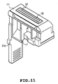
- FIG. 10 an external view of a liquid ejection head cartridge according to the present invention employing the ink-jet head shown in Figs. 1 to 3, namely an ink-jet head cartridge (hereinafter referred to as head cartridge) is shown in Fig. 10, and an external view of the major portion thereof is shown in Fig. 11.
- a head cartridge 40 as illustrates is a serial type, and the major portion is constituted of the ink-jet head 10 and a liquid tank 41 storing a liquid, such as an ink.
- the liquid, such as the ink is introduced into the common liquid chamber 23 in the head chip 12 from the liquid tank 41 via the liquid supply passage 19 (see Fig. 2) of the mold member 17.
- the head cartridge 40 in the shown embodiment is constructed by integrally forming the ink-jet head 10 and the liquid tank 41. However, it is also possible to construct the liquid tank 41 to be exchangeable with respect to the ink-jet head 10.
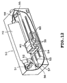
- FIG. 12 An external view of an ink-jet printing apparatus (hereinafter referred to as printing apparatus) according to the present invention employing the head cartridge 40 as set forth above is illustrated in Fig. 12.
- a carriage 54 On a pair of guide bars 53 which are arranged in parallel to a platen roller 52 driven to rotate by a feeding motor 51, a carriage 54 is slidably mounted.
- a scanning wire 57 On a pair of pulleys 55 and 56 rotatably mounted on both ends of the guide bar 53, a scanning wire 57 is wound around to extend along the guide bar 53. Both ends of the scanning wire 57 are connected to carriage 54.
- a carriage driving motor 58 To one of the pulley 55, a carriage driving motor 58 is connected.
- the carriage driving motor 58 is moved for scanning in the longitudinal direction along the platen roller 52 as being guided by the guide bars 53.
- a head cartridge 40 shown in Fig. 11 is mounted in positioned condition.
- the head cartridge 40 is exchangeable via an operation lever 59 for attaching and detaching.
- the ejection openings 27 of the ink-jet head 10 opposes with a printing medium 70, such as a paper fitted on the platen roller 52 with a predetermined clearance.
- a printing medium 70 such as a paper fitted on the platen roller 52 with a predetermined clearance.
- an ejection signal for the ink corresponding to a data from arbitrary data supply source is supplied via a flexible cable 60 connected to the carriage 54. Then, by a feeding operation of the printing medium 70 by the feeding motor 51 and scanning motion of the carriage 54 by the carriage driving motor 58, a desired data can be printed at the predetermined position of the printing medium 70.
- the one or more head cartridge 40 (two in the shown example) can be mounted on the carriage 54. While as the foregoing ink-jet head 10, the serial type ink-jet head is employed in the shown embodiment, it is possible to apply the head cartridge employing a fully-line type ink-jet head and other printing system.
- a printing system according to the present invention is illustrated in Fig. 13.
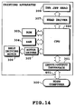
- a block diagram of the control system for the printing system is shown in Fig. 14.
- the shown printing system includes four ink tanks 204a, 204b, 204c and 204d respectively storing a yellow ink, magenta ink, cyan ink and black ink (hereinafter generally referred to as the ink tank 204), and four ink-jet heads 201a, 201b, 201c and 201d (hereinafter generally referred to as ink-jet head 201) respectively connected to the ink tanks 204.
- ink-jet head 201 not shown ejection openings are formed downwardly at a resolution of 360 dpi in Y direction, corresponding to the overall the entire width of a printing region in the printing medium 227.
- the ink-jet heads 201 in each of which power supply for respective of not shown electrothermal transducers is turned ON/OFF by head drivers 307 connected to the control circuit 219, are arranged at a predetermined interval along a transporting direction X of an endless transporting belt 206 in opposition to the platen 226 across the transporting belt 206.
- a head moving means 224 controlled the operation thereof by the control circuit 219 for performing a recovery process, the ink-jet heads 201 are moved up and down with respect to the platen 226.
- capping members 203a, 203b, 203c and 203d (hereinafter generally referred to as capping members 203) for performing recovery process for the ink-jet heads 210 by performing preparatory ejection with ejecting old ink in the not shown ink passages formed in the ink-jet heads 201, are arranged with a half pitch offset condition with respect to an arrangement interval of the ink-jet head 201.
- the capping member 203 is moved immediately below the ink-jet heads 201 to receive the waste ink ejected from the ejection openings during preparatory ejection.
- the transporting belt 206 transporting the printing medium 227 is wrapped around a driving roller 214 which is, in turn, connected to a belt driving motor 306.
- the operation of the transporting belt 206 is switched by a motor driver 305 connected to the control circuit 219.
- the feeding motor 211 for switching operation by the motor driver 212.
- the pair of feeding rollers 214 are driven to rotate.
- a pre-treatment device 251 and post-treatment device 252 to perform various process for the printing medium 227 before or after printing.
- the pre-treatment device 251 and post treatment 252 are provided at upstream side and the downstream side of the transporting passage of the printing medium 227.
- the pre-treatment and post-treatment are differentiated the content depending upon the kind of the printing medium 227 and the king of ink to perform printing.
- the printing medium 227 such as metal, plastic, ceramics
- ultraviolet ray or, ozone are irradiated to make the surface active for improving deposition ability of the ink.
- the printing medium 227 to easily cause static electricity, such as plastic, and whereby to easily absorb the dust on the surface, such dust may be a hazard for high quality printing. Therefore, in such case, by removing the static electricity of the printing medium 227 by means of an ionizer device to remove the dust.
- a process to add a material selected among alkaline substance, water-soluble substance, synthetic high polymer, water-soluble meal salt, urea, tiourea is performed as the pre-treatment.
- the pre-treatment should not be limited to those as explained and can be a process for adjusting the temperature of the printing medium 227 at an appropriate temperature for printing.
- the post process may be a heat treatment, fixing process for promoting fixing of the ink ejecting to the printing medium 227 by irradiation of the ultraviolet ray, a process for washing the processing liquid applied in the pre-treatment and residing without reaction, and the like.
- the ink-jet heads 201 are elevated upwardly away from the platen 226 to the recovering position. Then, the capping members 203 are moved immediately below the ink-jet head 201 to perform recovery process of the ink-jet head 201. Thereafter, the capping members 203 are returned to the initial and stand-by position. Then, the ink-jet head 201 is moved down to an image forming position or toward the platen 226. Then, an electrifier (not shown) is actuated. In conjunction therewith, the transporting belt 206 is driven. Then, the printing medium 227 is mounted on the transporting belt 206 by the feeding roller 214. Then, predetermined color images are formed on the printing medium 227 by respective ink-jet heads 201.
- the printing apparatus receives a control signal of a printing information from a host computer 300.
- the printing information is temporarily stored in an input interface 301 in the printing apparatus, and in conjunction therewith, converted into data which can be processed in the printing apparatus to be input to CPU 302 acting commonly as the head driving signal supply means.
- CPU 302 performs process of the input data using the peripheral unit, such as RAM 204 on the basis of a control program stored in ROM 303 to convert into a printing data (image data).
- CPU 302 generates respective of driving data for driving the belt driving motor 306, the feeding motor 211 for transporting the printing medium 227 in synchronism with the image data, and the ink-jet heads 201, for printing at an appropriate position on the printing medium 227.
- the image data and the motor driving data are transmitted to the ink-jet head 201 are transmitted to the ink-jet heads 201 and the belt driving motor 306 via the head driver 307 and the motor drivers 305 and 212 for driving at controlled timing to form the image.
- the present invention achieves distinct effect when applied to a liquid ejecting head or a recording apparatus which has means for generating thermal energy such as electrothermal transducers or laser light, and which causes changes in liquid by the thermal energy so as to eject the liquid. This is because such a system can achieve a high density and high resolution recording.
- the on-demand type apparatus has electrothermal transducers, each disposed on a sheet or liquid passage that retains liquid, and operates as follows: first, one or more drive signals are applied to the electrothermal transducers to cause thermal energy corresponding to recording information; second, the thermal energy induces sudden temperature rise that exceeds the nucleate boiling so as to cause the film boiling on heating portions of the liquid ejecting head; and third, bubbles are grown in the liquid corresponding to the drive signals. By using the growth and collapse of the bubbles, the liquid is expelled from at least one of the liquid ejection openings of the head to form one or more liquid drops.
- the drive signal in the form of a pulse is preferable because the growth and collapse of the bubbles can be achieved instantaneously and suitably by this form of drive signal.
- a drive signal in the form of a pulse those described in U.S. patent Nos. 4,463,359 and 4,345,262 are preferable.
- the rate of temperature rise of the heating portions described in U.S. patent No. 4,313,124 be adopted to achieve better recording.
- U.S. patent Nos. 4,558,333 and 4,459,600 disclose the following structure of a liquid ejecting head, which is incorporated to the present invention: this structure includes heating portions disposed on bent portions in addition to a combination of the ejection openings, liquid passages and the electrothermal transducers disclosed in the above patents. Moreover, the present invention can be applied to structures disclosed in Japanese Patent Application Laying-open Nos. 123670/1984 and 138461/1984 in order to achieve similar effects.
- the former discloses a structure in which a slit common to all the electrothermal transducers is used as ejection openings of the electrothermal transducers, and the latter discloses a structure in which openings for absorbing pressure waves caused by thermal energy are formed corresponding to the ejection openings.
- a recovery system or a preliminary auxiliary system for a liquid ejecting head as a constituent of the recording apparatus because they serve to make the effect of the present invention more reliable.
- the recovery system are a capping means and a cleaning means for the liquid ejecting head, and a pressure or suction means for the liquid ejecting head.
- the preliminary auxiliary system are a preliminary heating means utilizing electrothermal transducers or a combination of other heater elements and the electrothermal transducers, and a means for carrying out preliminary ejection of liquid independently of the ejection for recording. These systems are effective for reliable recording.
- the number and type of liquid ejecting heads to be mounted on a recording apparatus can be also changed.
- only one liquid ejecting head corresponding to a single color ink, or a plurality of liquid ejecting heads corresponding to a plurality of inks different in color or concentration can be used.
- the present invention can be effectively applied to an apparatus having at least one of the monochromatic, multi-color and full-color modes.
- the monochromatic mode performs recording by using only one major color such as black.
- the multi-color mode carries out recording by using different colors, and the full-color mode performs recording by color mixing.
- the treatment liquid printing ability enhancing liquid
- the printing ability of the ink depending upon the printing medium is ejected from the liquid ejection head.
- the printing apparatus in addition to that employed as an image output terminal of an information processing system, such as computer, which performs printing for the printing medium, such as paper, cloth leather, metal, plastic, glass, wood or ceramic, it can also be a facsimile machine having transmitting and receiving function, a textile printing apparatus and the like.
- a liquid ejection head includes a head chip (12) having a plurality of ejection openings (15), ejection energy generating means (20) for ejecting a liquid from the ejection openings (15), and a liquid chamber (23) communicated with the ejection openings (15) and being supplied a liquid, an electrical wiring substrate (11) formed with a chip installation hole (13) arranged wherein the head chip (12), a plurality of lead terminals (14) projecting into the chip installation hole (13) of the electrical wiring substrate (11) and being connected to the head chip (12) for supplying electric power to the ejection energy generating means (20), and a sealing material layer (16) sealing connecting portion between the lead terminals (14) and the head chip (12) and formed over the electrical wiring substrate (11) and the head chip (12), and a resin catching portion (26) being provided in a gap between the chip installation hole (13) and the head chip (12) for receiving the seal resin for achieving high strength of the connecting portion between the head chip (12) and the electric wiring substrate (11), and to achieve good seal.
Landscapes
- Engineering & Computer Science (AREA)
- Manufacturing & Machinery (AREA)
- Particle Formation And Scattering Control In Inkjet Printers (AREA)
- Ink Jet (AREA)
Applications Claiming Priority (6)
| Application Number | Priority Date | Filing Date | Title |
|---|---|---|---|
| JP201362/96 | 1996-07-31 | ||
| JP202223/96 | 1996-07-31 | ||
| JP20136296A JPH1044441A (ja) | 1996-07-31 | 1996-07-31 | インクジェットヘッドおよびインクジェットカートリッジおよびインクジェット装置ならびにインクジェットヘッドの製造方法 |
| JP20222396A JP3554113B2 (ja) | 1996-07-31 | 1996-07-31 | 液体吐出ヘッド、液体吐出ヘッドの製造方法、液体吐出装置、および記録システム |
| JP20222396 | 1996-07-31 | ||
| JP20136296 | 1996-07-31 |
Publications (3)
| Publication Number | Publication Date |
|---|---|
| EP0822081A2 true EP0822081A2 (de) | 1998-02-04 |
| EP0822081A3 EP0822081A3 (de) | 1998-09-23 |
| EP0822081B1 EP0822081B1 (de) | 2004-10-13 |
Family
ID=26512749
Family Applications (1)
| Application Number | Title | Priority Date | Filing Date |
|---|---|---|---|
| EP97113149A Expired - Lifetime EP0822081B1 (de) | 1996-07-31 | 1997-07-30 | Flüssigkeitsausstosskopf, Flüssigkeitsausstosskopfkartusche, Druckapparat, Drucksystem und Herstellungsverfahren für einen Flüssigkeitsausstosskopf |
Country Status (3)
| Country | Link |
|---|---|
| US (1) | US6084612A (de) |
| EP (1) | EP0822081B1 (de) |
| DE (1) | DE69731150T2 (de) |
Cited By (3)
| Publication number | Priority date | Publication date | Assignee | Title |
|---|---|---|---|---|
| WO2003018317A1 (en) * | 2001-08-31 | 2003-03-06 | Silverbrook Research Pty. Ltd. | An adhesive-based ink jet print head assembly |
| SG157222A1 (en) * | 2002-03-26 | 2009-12-29 | Sony Corp | Liquid ejection apparatus |
| CN105082755A (zh) * | 2014-05-12 | 2015-11-25 | 佳能株式会社 | 液体喷射头、制造液体喷射头的方法及液体喷射装置 |
Families Citing this family (19)
| Publication number | Priority date | Publication date | Assignee | Title |
|---|---|---|---|---|
| US6371597B1 (en) * | 2000-01-20 | 2002-04-16 | Lexmark International, Inc. | Tab circuit to minimize corrosion due to ink |
| JP3654116B2 (ja) * | 2000-03-10 | 2005-06-02 | セイコーエプソン株式会社 | 半導体装置及びその製造方法、回路基板並びに電子機器 |
| JP4632386B2 (ja) * | 2000-12-21 | 2011-02-16 | キヤノン株式会社 | 液体吐出記録ヘッド |
| JP4669138B2 (ja) * | 2001-02-22 | 2011-04-13 | キヤノン株式会社 | インクジェット記録ヘッドの製造方法 |
| US7118199B2 (en) * | 2003-02-06 | 2006-10-10 | Canon Kabushiki Kaisha | Liquid jet recording head |
| JP4332416B2 (ja) * | 2003-12-12 | 2009-09-16 | キヤノン株式会社 | インクジェット記録ヘッド |
| WO2006009235A1 (en) * | 2004-07-22 | 2006-01-26 | Canon Kabushiki Kaisha | Ink jet recording head and recording apparatus |
| WO2006009236A1 (en) * | 2004-07-22 | 2006-01-26 | Canon Kabushiki Kaisha | Ink jet recording head and ink jet recording apparatus |
| JP4290154B2 (ja) * | 2004-12-08 | 2009-07-01 | キヤノン株式会社 | 液体吐出記録ヘッドおよびインクジェット記録装置 |
| US7971966B2 (en) * | 2006-12-15 | 2011-07-05 | Canon Kabushiki Kaisha | Ink jet recording head |
| JP4958604B2 (ja) * | 2007-04-02 | 2012-06-20 | キヤノン株式会社 | インクジェット記録ヘッド |
| JP5495504B2 (ja) * | 2007-05-01 | 2014-05-21 | キヤノン株式会社 | インクジェット記録へッドの製造方法 |
| JP2010000632A (ja) * | 2008-06-18 | 2010-01-07 | Canon Inc | インクジェットヘッド用基板および該基板を具えるインクジェットヘッド |
| US8152279B2 (en) * | 2008-06-18 | 2012-04-10 | Canon Kabushiki Kaisha | Liquid ejection head having substrate with nickel-containing layer |
| JP5528071B2 (ja) * | 2009-11-25 | 2014-06-25 | キヤノン株式会社 | 液体噴射記録ヘッドおよび液体噴射記録ヘッドの製造方法 |
| JP5631054B2 (ja) * | 2010-05-12 | 2014-11-26 | キヤノン株式会社 | 液体吐出ヘッドおよびその製造方法 |
| JP5843444B2 (ja) * | 2011-01-07 | 2016-01-13 | キヤノン株式会社 | 液体吐出ヘッドの製造方法および液体吐出ヘッド |
| JP5828682B2 (ja) * | 2011-06-06 | 2015-12-09 | キヤノン株式会社 | 液体吐出ヘッドの製造方法 |
| JP5858813B2 (ja) * | 2012-02-06 | 2016-02-10 | キヤノン株式会社 | 液体吐出ヘッド及びその製造方法 |
Family Cites Families (21)
| Publication number | Priority date | Publication date | Assignee | Title |
|---|---|---|---|---|
| CA1127227A (en) * | 1977-10-03 | 1982-07-06 | Ichiro Endo | Liquid jet recording process and apparatus therefor |
| US4330787A (en) * | 1978-10-31 | 1982-05-18 | Canon Kabushiki Kaisha | Liquid jet recording device |
| US4345262A (en) * | 1979-02-19 | 1982-08-17 | Canon Kabushiki Kaisha | Ink jet recording method |
| US4463359A (en) * | 1979-04-02 | 1984-07-31 | Canon Kabushiki Kaisha | Droplet generating method and apparatus thereof |
| US4313124A (en) * | 1979-05-18 | 1982-01-26 | Canon Kabushiki Kaisha | Liquid jet recording process and liquid jet recording head |
| US4558333A (en) * | 1981-07-09 | 1985-12-10 | Canon Kabushiki Kaisha | Liquid jet recording head |
| JPS59123670A (ja) * | 1982-12-28 | 1984-07-17 | Canon Inc | インクジエツトヘツド |
| JPS59138461A (ja) * | 1983-01-28 | 1984-08-08 | Canon Inc | 液体噴射記録装置 |
| JPH064325B2 (ja) * | 1984-06-11 | 1994-01-19 | キヤノン株式会社 | 液体噴射ヘッド |
| US4881318A (en) * | 1984-06-11 | 1989-11-21 | Canon Kabushiki Kaisha | Method of manufacturing a liquid jet recording head |
| US4860033A (en) * | 1987-02-04 | 1989-08-22 | Canon Kabushiki Kaisha | Base plate having an oxidation film and an insulating film for ink jet recording head and ink jet recording head using said base plate |
| JPH04175728A (ja) * | 1990-11-08 | 1992-06-23 | Minolta Camera Co Ltd | 固体走査型光プリントヘッド |
| EP0490668B1 (de) * | 1990-12-12 | 1996-10-16 | Canon Kabushiki Kaisha | Tintenstrahlaufzeichnung |
| US5479197A (en) * | 1991-07-11 | 1995-12-26 | Canon Kabushiki Kaisha | Head for recording apparatus |
| EP0525787B1 (de) * | 1991-08-01 | 1996-10-16 | Canon Kabushiki Kaisha | Aufzeichnungskopfherstellungsverfahren |
| JP3103404B2 (ja) * | 1991-10-22 | 2000-10-30 | キヤノン株式会社 | インクジェット記録ヘッドの製造方法、インクジェット記録ヘッドおよびインクジェット記録装置 |
| US5434607A (en) * | 1992-04-02 | 1995-07-18 | Hewlett-Packard Company | Attachment of nozzle plate to flexible circuit for facilitating assembly of printhead |
| EP0585854B1 (de) * | 1992-08-31 | 1998-11-11 | Canon Kabushiki Kaisha | Tintenstrahlkopfherstellungsverfahren mittels Bearbeitung durch Ionen und Tintenstrahlkopf |
| JP3115720B2 (ja) * | 1992-09-29 | 2000-12-11 | キヤノン株式会社 | インクジェット記録ヘッド、該記録ヘッドを備えたインクジェット記録装置及び該記録ヘッドの製造方法 |
| US5847729A (en) * | 1993-06-14 | 1998-12-08 | Canon Kabushiki Kaisha | Ink-jet printing apparatus and method, and printed matter obtained thereby and processed article obtained from printed matter |
| JP3268937B2 (ja) * | 1994-04-14 | 2002-03-25 | キヤノン株式会社 | インクジェット記録ヘッド用基板及びそれを用いたヘッド |
-
1997
- 1997-07-25 US US08/900,290 patent/US6084612A/en not_active Expired - Lifetime
- 1997-07-30 DE DE69731150T patent/DE69731150T2/de not_active Expired - Lifetime
- 1997-07-30 EP EP97113149A patent/EP0822081B1/de not_active Expired - Lifetime
Cited By (9)
| Publication number | Priority date | Publication date | Assignee | Title |
|---|---|---|---|---|
| US6616271B2 (en) | 1999-10-19 | 2003-09-09 | Silverbrook Research Pty Ltd | Adhesive-based ink jet print head assembly |
| US7070265B2 (en) | 1999-10-19 | 2006-07-04 | Silverbrook Research Pty Ltd | Adhesive-based ink jet print head assembly |
| US7287829B2 (en) | 1999-10-19 | 2007-10-30 | Silverbrook Research Pty Ltd | Printhead assembly configured for relative movement between the printhead IC and its carrier |
| US8113625B2 (en) | 1999-10-19 | 2012-02-14 | Silverbrook Research Pty Ltd | Flexible printhead assembly with resiliently flexible adhesive |
| WO2003018317A1 (en) * | 2001-08-31 | 2003-03-06 | Silverbrook Research Pty. Ltd. | An adhesive-based ink jet print head assembly |
| AU2002356075B2 (en) * | 2001-08-31 | 2005-04-21 | Memjet Technology Limited | An adhesive-based ink jet print head assembly |
| EP1432585A4 (de) * | 2001-08-31 | 2005-12-21 | Silverbrook Res Pty Ltd | Tintenstrahldruckkopfanordnung auf klebstoffbasis |
| SG157222A1 (en) * | 2002-03-26 | 2009-12-29 | Sony Corp | Liquid ejection apparatus |
| CN105082755A (zh) * | 2014-05-12 | 2015-11-25 | 佳能株式会社 | 液体喷射头、制造液体喷射头的方法及液体喷射装置 |
Also Published As
| Publication number | Publication date |
|---|---|
| EP0822081B1 (de) | 2004-10-13 |
| US6084612A (en) | 2000-07-04 |
| DE69731150T2 (de) | 2005-12-22 |
| EP0822081A3 (de) | 1998-09-23 |
| DE69731150D1 (de) | 2004-11-18 |
Similar Documents
| Publication | Publication Date | Title |
|---|---|---|
| EP0822081B1 (de) | Flüssigkeitsausstosskopf, Flüssigkeitsausstosskopfkartusche, Druckapparat, Drucksystem und Herstellungsverfahren für einen Flüssigkeitsausstosskopf | |
| JP2831804B2 (ja) | インクジェット記録装置の回復方法 | |
| EP0581298B1 (de) | Farbstrahlaufzeichnungskopf, Kassette für einen Tintenstrahlaufzeichnungskopf, Aufzeichnungsgerät damit versehen und Herstellungsverfahren des Kopfes | |
| TWI295969B (en) | Ink jet printing head and ink jet printing apparatus using the same | |
| EP1481805B1 (de) | Substrat für einen Tintenstrahlaufzeichnungskopf | |
| EP0822077B1 (de) | Flüssigkeitsausstosskopf und Verfahren zur Herstellung desselben | |
| JP3187607B2 (ja) | インクジェット記録装置 | |
| JPH0825635A (ja) | インクジェットプリント装置およびプリントヘッドユニット | |
| EP1177903B1 (de) | Flüssigkeitsausstosskopf und Flüssigkeitsausstossvorrichtung | |
| US6328422B1 (en) | Ink jet head cartridge having a folded wiring member | |
| JPH09323414A (ja) | インクジェット記録装置 | |
| JPH1044441A (ja) | インクジェットヘッドおよびインクジェットカートリッジおよびインクジェット装置ならびにインクジェットヘッドの製造方法 | |
| JP3219641B2 (ja) | インクジェット記録装置およびインクの残量低下の判別方法ならびに情報処理装置 | |
| JP3115755B2 (ja) | インクジェット記録ヘッド、その製造方法およびインクジェット記録装置 | |
| JP3554113B2 (ja) | 液体吐出ヘッド、液体吐出ヘッドの製造方法、液体吐出装置、および記録システム | |
| JP2654220B2 (ja) | 記録ヘッド及び前記記録ヘッドを装着可能な記録装置 | |
| JP5009093B2 (ja) | 圧電アクチュエータ、液体吐出ヘッド、液体吐出装置及び画像形成装置 | |
| EP0819535A2 (de) | Verfahren und Apparat zum Tintenstrahldrucken von Textilien | |
| JP3416442B2 (ja) | インクジェットヘッドおよびインクジェット装置 | |
| EP0933224B1 (de) | Tintenstrahlaufzeichnungskopf und Tintenstrahlaufzeichnungsvorrichtung | |
| JPH08300656A (ja) | インクジェット記録ヘッド、インクジェット記録装置および情報処理システム | |
| JP3495897B2 (ja) | インクジェット記録ヘッド及びインクジェットカートリッジ | |
| JP3639698B2 (ja) | 液体吐出ヘッド、ヘッドカートリッジ、液体吐出記録装置、および液体吐出ヘッドの製造方法 | |
| JPH09123456A (ja) | インクジェットヘッド、該ヘッド用基板、インクジェットカートリッジ及びインクジェット装置 | |
| JPH07290711A (ja) | インクジェットヘッド、インクジェットヘッドカートリッジ、インクジェットヘッドキット、インクジェット記録装置、インクジェットヘッドの製造方法およびインクの注入方法 |
Legal Events
| Date | Code | Title | Description |
|---|---|---|---|
| PUAI | Public reference made under article 153(3) epc to a published international application that has entered the european phase |
Free format text: ORIGINAL CODE: 0009012 |
|
| AK | Designated contracting states |
Kind code of ref document: A2 Designated state(s): DE FR GB IT |
|
| AX | Request for extension of the european patent |
Free format text: AL;LT;LV;RO;SI |
|
| PUAL | Search report despatched |
Free format text: ORIGINAL CODE: 0009013 |
|
| AK | Designated contracting states |
Kind code of ref document: A3 Designated state(s): AT BE CH DE DK ES FI FR GB GR IE IT LI LU MC NL PT SE |
|
| AX | Request for extension of the european patent |
Free format text: AL;LT;LV;RO;SI |
|
| 17P | Request for examination filed |
Effective date: 19990208 |
|
| AKX | Designation fees paid |
Free format text: DE FR GB IT |
|
| RBV | Designated contracting states (corrected) |
Designated state(s): DE FR GB IT |
|
| 17Q | First examination report despatched |
Effective date: 20010517 |
|
| GRAP | Despatch of communication of intention to grant a patent |
Free format text: ORIGINAL CODE: EPIDOSNIGR1 |
|
| GRAS | Grant fee paid |
Free format text: ORIGINAL CODE: EPIDOSNIGR3 |
|
| GRAA | (expected) grant |
Free format text: ORIGINAL CODE: 0009210 |
|
| AK | Designated contracting states |
Kind code of ref document: B1 Designated state(s): DE FR GB IT |
|
| PG25 | Lapsed in a contracting state [announced via postgrant information from national office to epo] |
Ref country code: IT Free format text: LAPSE BECAUSE OF FAILURE TO SUBMIT A TRANSLATION OF THE DESCRIPTION OR TO PAY THE FEE WITHIN THE PRESCRIBED TIME-LIMIT;WARNING: LAPSES OF ITALIAN PATENTS WITH EFFECTIVE DATE BEFORE 2007 MAY HAVE OCCURRED AT ANY TIME BEFORE 2007. THE CORRECT EFFECTIVE DATE MAY BE DIFFERENT FROM THE ONE RECORDED. Effective date: 20041013 Ref country code: FR Free format text: LAPSE BECAUSE OF FAILURE TO SUBMIT A TRANSLATION OF THE DESCRIPTION OR TO PAY THE FEE WITHIN THE PRESCRIBED TIME-LIMIT Effective date: 20041013 |
|
| REG | Reference to a national code |
Ref country code: GB Ref legal event code: FG4D |
|
| REF | Corresponds to: |
Ref document number: 69731150 Country of ref document: DE Date of ref document: 20041118 Kind code of ref document: P |
|
| PLBE | No opposition filed within time limit |
Free format text: ORIGINAL CODE: 0009261 |
|
| STAA | Information on the status of an ep patent application or granted ep patent |
Free format text: STATUS: NO OPPOSITION FILED WITHIN TIME LIMIT |
|
| 26N | No opposition filed |
Effective date: 20050714 |
|
| EN | Fr: translation not filed | ||
| PGFP | Annual fee paid to national office [announced via postgrant information from national office to epo] |
Ref country code: DE Payment date: 20140731 Year of fee payment: 18 |
|
| PGFP | Annual fee paid to national office [announced via postgrant information from national office to epo] |
Ref country code: GB Payment date: 20140724 Year of fee payment: 18 |
|
| REG | Reference to a national code |
Ref country code: DE Ref legal event code: R119 Ref document number: 69731150 Country of ref document: DE |
|
| GBPC | Gb: european patent ceased through non-payment of renewal fee |
Effective date: 20150730 |
|
| PG25 | Lapsed in a contracting state [announced via postgrant information from national office to epo] |
Ref country code: DE Free format text: LAPSE BECAUSE OF FAILURE TO SUBMIT A TRANSLATION OF THE DESCRIPTION OR TO PAY THE FEE WITHIN THE PRESCRIBED TIME-LIMIT Effective date: 20160202 Ref country code: GB Free format text: LAPSE BECAUSE OF NON-PAYMENT OF DUE FEES Effective date: 20150730 |