EP0822165A1 - Abwasserreinigungsverfahren - Google Patents
Abwasserreinigungsverfahren Download PDFInfo
- Publication number
- EP0822165A1 EP0822165A1 EP19970202361 EP97202361A EP0822165A1 EP 0822165 A1 EP0822165 A1 EP 0822165A1 EP 19970202361 EP19970202361 EP 19970202361 EP 97202361 A EP97202361 A EP 97202361A EP 0822165 A1 EP0822165 A1 EP 0822165A1
- Authority
- EP
- European Patent Office
- Prior art keywords
- sludge
- water
- processes
- digester
- anoxic
- Prior art date
- Legal status (The legal status is an assumption and is not a legal conclusion. Google has not performed a legal analysis and makes no representation as to the accuracy of the status listed.)
- Granted
Links
- 238000000034 method Methods 0.000 title claims abstract description 141
- 239000002351 wastewater Substances 0.000 title claims abstract description 51
- 239000010802 sludge Substances 0.000 claims abstract description 154
- XLYOFNOQVPJJNP-UHFFFAOYSA-N water Substances O XLYOFNOQVPJJNP-UHFFFAOYSA-N 0.000 claims abstract description 130
- 229910019142 PO4 Inorganic materials 0.000 claims abstract description 55
- 238000004062 sedimentation Methods 0.000 claims abstract description 39
- 239000010452 phosphate Substances 0.000 claims abstract description 29
- NBIIXXVUZAFLBC-UHFFFAOYSA-K phosphate Chemical compound [O-]P([O-])([O-])=O NBIIXXVUZAFLBC-UHFFFAOYSA-K 0.000 claims abstract description 24
- 241000894006 Bacteria Species 0.000 claims abstract description 19
- 239000000203 mixture Substances 0.000 claims abstract description 8
- 239000008213 purified water Substances 0.000 claims abstract description 4
- 235000021317 phosphate Nutrition 0.000 claims description 49
- 150000003013 phosphoric acid derivatives Chemical class 0.000 claims description 26
- 239000001301 oxygen Substances 0.000 claims description 19
- 229910052760 oxygen Inorganic materials 0.000 claims description 19
- QVGXLLKOCUKJST-UHFFFAOYSA-N atomic oxygen Chemical compound [O] QVGXLLKOCUKJST-UHFFFAOYSA-N 0.000 claims description 16
- 238000009434 installation Methods 0.000 claims description 13
- 239000003795 chemical substances by application Substances 0.000 claims description 5
- 229920006395 saturated elastomer Polymers 0.000 claims description 2
- IJGRMHOSHXDMSA-UHFFFAOYSA-N Atomic nitrogen Chemical compound N#N IJGRMHOSHXDMSA-UHFFFAOYSA-N 0.000 description 23
- 239000000126 substance Substances 0.000 description 13
- 229910052757 nitrogen Inorganic materials 0.000 description 11
- 229910002651 NO3 Inorganic materials 0.000 description 8
- 125000005931 tert-butyloxycarbonyl group Chemical group [H]C([H])([H])C(OC(*)=O)(C([H])([H])[H])C([H])([H])[H] 0.000 description 8
- NHNBFGGVMKEFGY-UHFFFAOYSA-N Nitrate Chemical compound [O-][N+]([O-])=O NHNBFGGVMKEFGY-UHFFFAOYSA-N 0.000 description 7
- 238000005273 aeration Methods 0.000 description 7
- 244000005700 microbiome Species 0.000 description 6
- 150000002823 nitrates Chemical class 0.000 description 6
- 238000000746 purification Methods 0.000 description 6
- 239000002352 surface water Substances 0.000 description 5
- 230000031018 biological processes and functions Effects 0.000 description 4
- 238000005192 partition Methods 0.000 description 4
- 235000014113 dietary fatty acids Nutrition 0.000 description 2
- 229930195729 fatty acid Natural products 0.000 description 2
- 239000000194 fatty acid Substances 0.000 description 2
- 150000004665 fatty acids Chemical class 0.000 description 2
- 239000007789 gas Substances 0.000 description 2
- 238000011946 reduction process Methods 0.000 description 2
- 239000002699 waste material Substances 0.000 description 2
- 229920000089 Cyclic olefin copolymer Polymers 0.000 description 1
- OAICVXFJPJFONN-UHFFFAOYSA-N Phosphorus Chemical compound [P] OAICVXFJPJFONN-UHFFFAOYSA-N 0.000 description 1
- 230000003851 biochemical process Effects 0.000 description 1
- 230000033228 biological regulation Effects 0.000 description 1
- 238000010924 continuous production Methods 0.000 description 1
- 230000001419 dependent effect Effects 0.000 description 1
- 229910001873 dinitrogen Inorganic materials 0.000 description 1
- 239000010840 domestic wastewater Substances 0.000 description 1
- 230000000694 effects Effects 0.000 description 1
- 238000005265 energy consumption Methods 0.000 description 1
- 230000007613 environmental effect Effects 0.000 description 1
- 238000012851 eutrophication Methods 0.000 description 1
- 230000012010 growth Effects 0.000 description 1
- 239000010842 industrial wastewater Substances 0.000 description 1
- 239000007788 liquid Substances 0.000 description 1
- 238000004519 manufacturing process Methods 0.000 description 1
- 229910017464 nitrogen compound Inorganic materials 0.000 description 1
- 150000002830 nitrogen compounds Chemical class 0.000 description 1
- 235000015097 nutrients Nutrition 0.000 description 1
- 230000003647 oxidation Effects 0.000 description 1
- 238000007254 oxidation reaction Methods 0.000 description 1
- 239000002245 particle Substances 0.000 description 1
- 238000005191 phase separation Methods 0.000 description 1
- 229910052698 phosphorus Inorganic materials 0.000 description 1
- 239000011574 phosphorus Substances 0.000 description 1
- 239000002244 precipitate Substances 0.000 description 1
- 230000035943 smell Effects 0.000 description 1
Images

Classifications
-
- C—CHEMISTRY; METALLURGY
- C02—TREATMENT OF WATER, WASTE WATER, SEWAGE, OR SLUDGE
- C02F—TREATMENT OF WATER, WASTE WATER, SEWAGE, OR SLUDGE
- C02F3/00—Biological treatment of water, waste water, or sewage
- C02F3/02—Aerobic processes
- C02F3/12—Activated sludge processes
- C02F3/1236—Particular type of activated sludge installations
- C02F3/1242—Small compact installations for use in homes, apartment blocks, hotels or the like
- C02F3/1247—Small compact installations for use in homes, apartment blocks, hotels or the like comprising circular tanks with elements, e.g. decanters, aeration basins, in the form of segments, crowns or sectors
-
- C—CHEMISTRY; METALLURGY
- C02—TREATMENT OF WATER, WASTE WATER, SEWAGE, OR SLUDGE
- C02F—TREATMENT OF WATER, WASTE WATER, SEWAGE, OR SLUDGE
- C02F3/00—Biological treatment of water, waste water, or sewage
- C02F3/30—Aerobic and anaerobic processes
- C02F3/308—Biological phosphorus removal
-
- Y—GENERAL TAGGING OF NEW TECHNOLOGICAL DEVELOPMENTS; GENERAL TAGGING OF CROSS-SECTIONAL TECHNOLOGIES SPANNING OVER SEVERAL SECTIONS OF THE IPC; TECHNICAL SUBJECTS COVERED BY FORMER USPC CROSS-REFERENCE ART COLLECTIONS [XRACs] AND DIGESTS
- Y02—TECHNOLOGIES OR APPLICATIONS FOR MITIGATION OR ADAPTATION AGAINST CLIMATE CHANGE
- Y02A—TECHNOLOGIES FOR ADAPTATION TO CLIMATE CHANGE
- Y02A20/00—Water conservation; Efficient water supply; Efficient water use
- Y02A20/20—Controlling water pollution; Waste water treatment
- Y02A20/208—Off-grid powered water treatment
-
- Y—GENERAL TAGGING OF NEW TECHNOLOGICAL DEVELOPMENTS; GENERAL TAGGING OF CROSS-SECTIONAL TECHNOLOGIES SPANNING OVER SEVERAL SECTIONS OF THE IPC; TECHNICAL SUBJECTS COVERED BY FORMER USPC CROSS-REFERENCE ART COLLECTIONS [XRACs] AND DIGESTS
- Y02—TECHNOLOGIES OR APPLICATIONS FOR MITIGATION OR ADAPTATION AGAINST CLIMATE CHANGE
- Y02W—CLIMATE CHANGE MITIGATION TECHNOLOGIES RELATED TO WASTEWATER TREATMENT OR WASTE MANAGEMENT
- Y02W10/00—Technologies for wastewater treatment
- Y02W10/10—Biological treatment of water, waste water, or sewage
Definitions
- the invention relates to a method for the treatment of waste water.
- Aerobic processes take place in aeration tanks, for example.
- nitrogen and nitrogen compounds such as NH 4 + from the waste water are converted into nitrates and pollution - expressed in biochemical oxygen consuming units, or BOCs, or, depending on the method of determination, COCs - is removed from the waste water by breaking down or binding these BOCs to the microorganisms with the aid of oxygen.
- nitrates formed are then removed again in an anoxic process with the aid of microorganisms.
- An anoxic process takes place in a low-oxygen but nitrate-containing environment in which phosphate-accumulating bacteria can also take up large amounts of phosphates from the waste water, with the nitrate serving as an oxygen source for the bacteria. In this way phosphate is removed from the waste water and fixed in sludge, and nitrates are removed.
- Anaerobic processes also take place in a low-oxygen environment which is also low in nitrates.
- reduction processes can also give rise to fatty acids which are taken up by the bacteria, with the energy needed for this being obtained by releasing the intracellularly stored phosphates to the water.
- the phosphate-rich water thus obtained can also be purified with the aid of chemicals which bind and precipitate the phosphates.
- the number of times and the order in which the waste water goes through the processes is inter alia dependent on the degree and nature of the pollution of the waste water.
- the object of the invention is a process for the treatment of waste water in which the various processes each take place in separate digesters, with the processes being integrated and attuned to each other in such a way that the best possible purification takes place at the lowest possible costs, preferably in a single-sludge system in which the water goes through all the processes in a single main stream.
- This object of the invention is achieved by a method of the type described in the opening paragraphs, in which the processes to be gone through are carried out with the aid of a population of bacteria which mainly consists of denitrifying phosphate-removing bacteria, or DPBs, with the composition of the sludge water in the various processes being maintained in such a state, by means of return flows of the sludge water to previous processes, that the DBP population achieves an optimum size, while through the return flows DPBs, depending on the extent to which they are saturated in one process, are passed on or returned to another process.
- a population of bacteria which mainly consists of denitrifying phosphate-removing bacteria, or DPBs
- DPBs Denitrifying Phosphorus Removing Bacteria
- DPBs can release phosphates under anaerobic conditions and take up phosphates both under denitrifying conditions and under oxygen-rich conditions.
- the use of DPBs has important advantages. One important advantage is that less COD is needed for the removal of nitrogen and phosphates. The energy consumption, particularly for aeration, and the sludge production are also lower.
- part of the phosphate-rich water is withdrawn to a sedimentation zone or stripper which forms part of a digester in which the sludge water goes through the anaerobic process, after which agents are then added to the phosphate-rich water to bind phosphates, after which the bound phosphates flocculate and settle out in a separate tank, a sludge condenser or sedimentation tank for example, after which the low-phosphate water thus obtained is conveyed to the first anoxic process. Because the phosphates are taken out of the water in a separate branch line of processes, the chemicals used cannot end up in the sludge which has to undergo the anoxic and aerobic processes.
- part of the sludge water originating from the anoxic processes is fed to a variable digester which, depending on the nature and degree of pollution of the waste water or sludge water, is used either as an anoxic or as an aerobic digester, after which the sludge water is conveyed from the variable digester to the aerobic process.
- a variable digester which, depending on the nature and degree of pollution of the waste water or sludge water, is used either as an anoxic or as an aerobic digester, after which the sludge water is conveyed from the variable digester to the aerobic process.
- variable digester is switched from anoxic digester to aerobic digester at times of peak load. Under aerobic conditions the phosphate still present in the sludge water is fixed by the dephosphorylating bacteria and oxidation of nitrogen and oxygen-binding substances takes place.
- Part of the sludge water which has gone through the aerobic processes is preferably returned to the variable digester.
- the waste water can be purified even better and more effectively, particularly as regards the removal of phosphates, nitrogen and BOCs.
- Good denitrification can be achieved by the mixing of the sludge water from the aerobic digester with the sludge water which goes into the variable digester, while at the same time BOCs are broken down under anoxic conditions or under conditions which are to a limited extent aerobic.
- variable digester after passage through an anoxic process in the variable digester the nature of the sludge water which has gone through the anoxic process is determined, after which the variable digester is used an anoxic or as an aerobic digester, as required, depending on the nature of this sludge water. If for example the content of BOCs, the oxygen content of the sludge water or the redox potential is high after passage through the variable digester (at times of peak load, for example, when large quantities of waste water have to be treated), the variable digester can be used as an anoxic digester, so that BOCs and nitrogen are better removed.
- the oxygen content of the sludge water which has gone through the aerobic process is preferably determined after the aerobic process, after which the variable digester is used as an aerobic digester if the oxygen content is lower than a particular limit value, whereas the variable digester is used as an anoxic digester if the oxygen content is higher than this limit value. In this way it is possible continuously to determine, by a rapid method which is simple to carry out, whether the digester has to be used as an anoxic or as an aerobic digester.
- An improvement in the sedimentation properties of the sludge is achieved by mixing the sludge water which has just gone through the anaerobic process in the contact tank with sludge originating from the secondary sedimentation tank. This sludge has already passed through the entire treatment process. By mixing the returned sludge with the sludge water a readily sedimentable active sludge mixture is obtained as a result of the fact, for example, that fine and colloidal particles are captured by the sludge flocs in the return sludge.
- At least part of the waste water is preferably fed into an installation for separating waste water and sludge, after which sludge is removed, while the waste water for further processing is fed to the first process.
- Fig. 1 gives in schematic form an example of the execution of a method according to the invention.
- a preliminary sedimentation tank the waste water is separated into a sedimentable fraction or sludge and pre-sedimented waste water.
- the waste water is then mixed with anoxic sludge water which originates from an anoxic digester and which, up to and including this anoxic digester, has already passed through part of the treatment process.
- the mixture of waste water and anoxic sludge water is fed into an anaerobic digester, in which phosphates are given up by bacteria to the sludge water.
- reduction processes can give rise to fatty acids which are taken up by the bacteria, while phosphates are given up by the bacteria to the water.
- the anaerobic digester the sludge water is separated into a sedimenting layer of sludge water and an upper layer of phosphate-rich water.
- the upper layer of water which contains little sludge but is phosphate-rich, is pumped to a tank, for example a separate sedimentation tank or sludge condenser.
- chemicals which chemically bind the phosphates are added to the phosphate-rich water.
- the precipitated phosphate-rich sludge with chemically bound phosphates is removed, preferably after condensing, and further processed in a sludge processing installation.
- the remaining low-phosphate water is added to the sludge water again further on in the treatment process.
- the remaining sludge from the anaerobic digester is then conveyed to a mixing tank, which is also referred to as a contact tank.
- a mixing tank which is also referred to as a contact tank.
- the sludge water is mixed with sludge which has already gone through the entire process.
- the sedimentation properties of the sludge are in this way greatly improved.
- the sludge water is then conveyed to an anoxic digester.
- the sludge water from the contact tank is mixed with nitrate-rich sludge water which has already gone through several phases of the process and which originates from an aerobic digester.
- the low-phosphate water from the sludge condenser or sedimentation tank is also preferably added in this anoxic tank. Nitrates are removed from the sludge water by bacteria in this anoxic tank.
- Part of the anoxic sludge water from this anoxic digester is fed again to the anaerobic tank.
- variable digester can be used as an anoxic digester or as an aerobic digester, as required, depending on the nature and the degree of pollution of the waste water to be treated.
- the sludge water is then conveyed to an aerobic digester, after which a minimum content of nitrogen, phosphates and biochemical oxygen-consuming components is left in the sludge water.
- an aerobic digester Depending on the process conditions and the mode of use of the variable digester, the process thus comprises either two anoxic processes followed by one aerobic process or one anoxic process followed by two aerobic processes.
- the number and execution of the anoxic and aerobic processes, as well as the return flows needed, can be further varied depending on the content of components to be removed.
- Part of the sludge water is returned from the aerobic digester and then mixed with the sludge water originating from the contact tank, and then put into the anoxic digester, after which it goes through the subsequent processes again.
- Another part of the sludge water from the last aerobic digester is returned by mixing it with the anoxic sludge water originating from the anoxic digester and then putting it into the variable digester, after which it goes through the subsequent processes again.
- the remaining sludge water from the last aerobic digester is fed to a secondary sedimentation tank or two-phase separation. Here the sludge settles out and any floating layer is removed, giving clean water which by now has been purified to such an extent that it can be discharged to the surface water.
- Part of the separated sludge is returned to the contact tank, after which it goes through the subsequent processes again.
- the remaining sludge is removed and given further treatment in a sludge processing installation, just like the sludge from the preliminary sedimentation tank and the phosphate-rich sludge with the chemically bound phosphates. If the sedimentation tank for sedimentation of the phosphate-rich sludge has been designed as a sludge condenser, part of the sludge from the last sedimentation tank can be fed into this sludge condenser.
- Gases which may cause an environmental nuisance, such as unpleasant smells, are released in various of the processes forming part of the overall process. These gases are drawn off and treated in an air treatment installation.
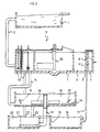
- Fig. 2 shows schematically, in cross-section, a possible installation for carrying out the method described above.
- Raw waste water is pre-sedimented in a preliminary sedimentation tank, 1, after which the waste water is fed via a conduit, 2, to a cylindrical digester, 3, which is divided into three concentric annular digesters, 4, 5 and 6, which enclose a central, concentric cylindrical digester, 7.
- the waste water is conveyed into the outermost annular tank, 4, which is used as an anaerobic digester.
- the anaerobic digester there are radial partitions, 8.
- the waste water which is located between the partitions, 8, does not flow around, and so the components present in the waste water settle out better.
- the waste water separates into phosphate-rich water which is located between the partitions, 8, and sludge water which is located in the bottom part, 9, of the anaerobic digester, 4.
- the phosphate-rich water is drawn off or 'stripped' from the compartments between the partitions, 8, and conveyed to the central tank, 7.
- the central tank, 7, chemicals which bind the phosphates and cause them to settle out as phosphate-rich sludge, which is removed to a processing installation, are added to the waste water.
- the central tank, 7, is provided with a stirrer, 10.
- the sludge water from part 9 of the anaerobic digester, 4, is conveyed to the adjacent tank, 5, which serves as a contact tank, where the waste water is mixed with sludge which via a conduit, 11, is conveyed from a secondary sedimentation tank, 12, to the end of the treatment process.
- the waste water is then conveyed to the annular digester, 6, which is used as an anoxic digester.
- the sludge water is also mixed with low-phosphate water originating from the central tank, 7.
- Propellers, 13, are fitted both in the anaerobic digester, 4, and in the contact tank, 5, and anoxic digester, 6.
- the variation in the sludge content with the depth of the tank, 4, 5 and 6, can be influenced by means of the speed regulation for these propellers, 13, whereby the sludge content of the entire system can also be influenced.
- the release of phosphates by the bacteria is in this way favourably influenced, while in the case of high, anoxic digesters the uptake of phosphates by bacteria is favourably influenced.
- variable digester From the anoxic digester, 6, the sludge water is conveyed via a conduit, 14, to a variable digester, 15, which depending on the process conditions can be operated either as an aerobic or as an anoxic digester, as desired.
- the variable digester is provided both with an aeration installation, for example a bubble aeration installation, 16, and with propellers, 17, and a stirrer, 18. If the variable digester, 15, needs to be operated as an aerobic digester, the aeration installation, 16, is started up, so that sufficient oxygen is available for starting up an aerobic process. If the variable digester, 15, is operated as an anoxic digester, the aeration installation, 16, is shut down and the propellers, 17, and the stirrer, 18, are started up.
- the waste water is admitted near the side wall and removed in the middle of the variable digester, 15, by means of a submerged overflow consisting of a vertical conduit, 19, whose exit end is slightly below the level of the liquid.
- the sludge water is conveyed via the conduit, 19, to an aerobic digester, 20, which is also provided with an aeration installation, 21. From the aerobic digester there are return flows via the conduits 22 and 23 to the anoxic tank, 6, and to the variable digester, 15, respectively.
- Another part is conveyed to a secondary sedimentation tank, 24, where the sludge settles out and where clean, treated water is drawn off and discharged to the surface water.
- Part of the sludge from this sedimentation tank is returned via the conduit 11 to the contact tank, 5, while another part of the sludge is removed to a processing installation.
Landscapes
- Life Sciences & Earth Sciences (AREA)
- Biodiversity & Conservation Biology (AREA)
- Microbiology (AREA)
- Hydrology & Water Resources (AREA)
- Engineering & Computer Science (AREA)
- Environmental & Geological Engineering (AREA)
- Water Supply & Treatment (AREA)
- Chemical & Material Sciences (AREA)
- Organic Chemistry (AREA)
- Health & Medical Sciences (AREA)
- Molecular Biology (AREA)
- Purification Treatments By Anaerobic Or Anaerobic And Aerobic Bacteria Or Animals (AREA)
- Separation Using Semi-Permeable Membranes (AREA)
Applications Claiming Priority (2)
| Application Number | Priority Date | Filing Date | Title |
|---|---|---|---|
| NL1003711 | 1996-07-31 | ||
| NL1003711A NL1003711C2 (nl) | 1996-07-31 | 1996-07-31 | Werkwijze voor het zuiveren van afvalwater. |
Publications (2)
| Publication Number | Publication Date |
|---|---|
| EP0822165A1 true EP0822165A1 (de) | 1998-02-04 |
| EP0822165B1 EP0822165B1 (de) | 2004-05-26 |
Family
ID=19763299
Family Applications (1)
| Application Number | Title | Priority Date | Filing Date |
|---|---|---|---|
| EP19970202361 Expired - Lifetime EP0822165B1 (de) | 1996-07-31 | 1997-07-28 | Abwasserreinigungsverfahren |
Country Status (4)
| Country | Link |
|---|---|
| EP (1) | EP0822165B1 (de) |
| AT (1) | ATE267774T1 (de) |
| DE (1) | DE69729249T2 (de) |
| NL (1) | NL1003711C2 (de) |
Cited By (6)
| Publication number | Priority date | Publication date | Assignee | Title |
|---|---|---|---|---|
| EP1114797A1 (de) * | 2000-01-05 | 2001-07-11 | Sirius B.V. | Vorrichtung zur Abwasserreinigung |
| WO2002012133A1 (de) * | 2000-08-03 | 2002-02-14 | Bioclar, A.S. | Belebtschlammverfahren und vorrichtung zur behandlung von abwasser mit stickstoff- und phosphor-entfernung |
| CN102153249A (zh) * | 2011-05-06 | 2011-08-17 | 北京剑平瑞华环保技术有限公司 | 一种有机废水的处理系统和方法 |
| CN107010794A (zh) * | 2017-06-06 | 2017-08-04 | 宁波德欣科技有限公司 | 一种染料废水处理装置及其方法 |
| CN109052820A (zh) * | 2018-08-14 | 2018-12-21 | 国网陕西省电力公司电力科学研究院 | 一种变电站污水处理零排放装置 |
| CN113149363A (zh) * | 2021-05-06 | 2021-07-23 | 杜普利 | 农村生活污水mbr一体化处理方法 |
Families Citing this family (3)
| Publication number | Priority date | Publication date | Assignee | Title |
|---|---|---|---|---|
| CN101182072B (zh) * | 2007-11-14 | 2010-06-02 | 哈尔滨工业大学 | 利用内源反硝化生物脱氮除磷使污泥减量的方法及反应系统 |
| CN101372378B (zh) * | 2008-04-30 | 2010-09-15 | 北京工业大学 | Sbr用于连续流双污泥反硝化除磷工艺快速启动的方法 |
| CN105731722B (zh) * | 2016-02-03 | 2019-04-19 | 杭州聚合顺新材料股份有限公司 | 锦纶切片工艺废水处理装置及其处理方法 |
Citations (4)
| Publication number | Priority date | Publication date | Assignee | Title |
|---|---|---|---|---|
| JPH04151000A (ja) * | 1990-10-16 | 1992-05-25 | Meidensha Corp | 窒素およびリンの同時除去方法およびその装置 |
| DE4100685A1 (de) * | 1991-01-11 | 1992-07-16 | Sued Chemie Ag | Verfahren zum reinigen von phosphate und stickstoffverbindungen enthaltenden abwaessern |
| US5380438A (en) * | 1993-08-17 | 1995-01-10 | City Of Atlanta | Treatment of wastewater through enhanced biological phosphorus removal |
| NL9401806A (nl) * | 1994-10-31 | 1996-06-03 | Rijkslandbouwhogeschool | Werkwijze voor het zuiveren van koolstof, fosfor en stikstof bevattend afvalwater. |
Family Cites Families (1)
| Publication number | Priority date | Publication date | Assignee | Title |
|---|---|---|---|---|
| US5393427A (en) * | 1992-04-09 | 1995-02-28 | Barnard; James L. | Process for the biological treatment of wastewater |
-
1996
- 1996-07-31 NL NL1003711A patent/NL1003711C2/nl not_active IP Right Cessation
-
1997
- 1997-07-28 AT AT97202361T patent/ATE267774T1/de not_active IP Right Cessation
- 1997-07-28 DE DE1997629249 patent/DE69729249T2/de not_active Expired - Lifetime
- 1997-07-28 EP EP19970202361 patent/EP0822165B1/de not_active Expired - Lifetime
Patent Citations (4)
| Publication number | Priority date | Publication date | Assignee | Title |
|---|---|---|---|---|
| JPH04151000A (ja) * | 1990-10-16 | 1992-05-25 | Meidensha Corp | 窒素およびリンの同時除去方法およびその装置 |
| DE4100685A1 (de) * | 1991-01-11 | 1992-07-16 | Sued Chemie Ag | Verfahren zum reinigen von phosphate und stickstoffverbindungen enthaltenden abwaessern |
| US5380438A (en) * | 1993-08-17 | 1995-01-10 | City Of Atlanta | Treatment of wastewater through enhanced biological phosphorus removal |
| NL9401806A (nl) * | 1994-10-31 | 1996-06-03 | Rijkslandbouwhogeschool | Werkwijze voor het zuiveren van koolstof, fosfor en stikstof bevattend afvalwater. |
Non-Patent Citations (3)
| Title |
|---|
| DATABASE WPI Section Ch Week 9227, Derwent World Patents Index; Class D15, AN 92-223744 * |
| J.J. VAN RIEL: "Het modified Renphosysteem", DOCTORAALVERSLAGEN VAKGROEP MILIEUTECHNOLOGIE, LANDBOUWUNIVERSITEIT, vol. 94, no. 5, July 1994 (1994-07-01), WAGENINGEN NL, XP002028379 * |
| PATENT ABSTRACTS OF JAPAN vol. 016, no. 437 (C - 0984) 11 September 1992 (1992-09-11) * |
Cited By (7)
| Publication number | Priority date | Publication date | Assignee | Title |
|---|---|---|---|---|
| EP1114797A1 (de) * | 2000-01-05 | 2001-07-11 | Sirius B.V. | Vorrichtung zur Abwasserreinigung |
| WO2002012133A1 (de) * | 2000-08-03 | 2002-02-14 | Bioclar, A.S. | Belebtschlammverfahren und vorrichtung zur behandlung von abwasser mit stickstoff- und phosphor-entfernung |
| CN102153249A (zh) * | 2011-05-06 | 2011-08-17 | 北京剑平瑞华环保技术有限公司 | 一种有机废水的处理系统和方法 |
| CN107010794A (zh) * | 2017-06-06 | 2017-08-04 | 宁波德欣科技有限公司 | 一种染料废水处理装置及其方法 |
| CN107010794B (zh) * | 2017-06-06 | 2022-11-01 | 宁波德欣科技有限公司 | 一种染料废水处理装置及其方法 |
| CN109052820A (zh) * | 2018-08-14 | 2018-12-21 | 国网陕西省电力公司电力科学研究院 | 一种变电站污水处理零排放装置 |
| CN113149363A (zh) * | 2021-05-06 | 2021-07-23 | 杜普利 | 农村生活污水mbr一体化处理方法 |
Also Published As
| Publication number | Publication date |
|---|---|
| ATE267774T1 (de) | 2004-06-15 |
| DE69729249D1 (de) | 2004-07-01 |
| DE69729249T2 (de) | 2005-06-23 |
| NL1003711C2 (nl) | 1998-02-05 |
| EP0822165B1 (de) | 2004-05-26 |
Similar Documents
| Publication | Publication Date | Title |
|---|---|---|
| US4160724A (en) | Waste water treatment | |
| US4460470A (en) | Process and apparatus for the biological purification of phosphate-containing wastewater | |
| US6086765A (en) | Multi-stage facultative wastewater treatment system and method hydrolyzing biosolids | |
| US5288405A (en) | Wastewater treatment with enhanced biological phosphorus removal and related purification processes | |
| US4999111A (en) | Process for treating wastewater | |
| EP0346013B1 (de) | Abwasserbehandlungsverfahren | |
| US5252214A (en) | Biological dephosphatization and (de)nitrification | |
| US5942108A (en) | Multi-phase dual cycle influent process | |
| US5393427A (en) | Process for the biological treatment of wastewater | |
| EP0408878B1 (de) | Verbesserte Beseitigung von Phosphaten in der Abwasserbehandlung mit Belebtschlammverfahren | |
| US6787035B2 (en) | Bioreactor for treating wastewater | |
| CN103373794A (zh) | 污水处理工艺及其专用的一体式污水处理装置 | |
| CA2995060C (en) | Continuous process for the treatment of wastewater | |
| RU2672419C1 (ru) | Система и способ биопленочной нитрификации-контактной денитрификации | |
| EP0822165B1 (de) | Abwasserreinigungsverfahren | |
| JP2661093B2 (ja) | 活性汚泥法による廃水処理方法 | |
| CA2300719A1 (en) | Membrane supported biofilm process | |
| GB2228930A (en) | Removal of nitrogen and phosphorus from sewage | |
| EP1027292B1 (de) | Verfahren zur biologischen reinigung von abwasser unter zurückhaltung von schlamm | |
| CN115872563A (zh) | 一种多段ao-mbbr零碳源污水脱氮方法 | |
| KR100377947B1 (ko) | 수중퇴비화 장치 및 그를 이용한 하폐수의 정화방법 | |
| JP3355121B2 (ja) | 有機性汚水の処理方法 | |
| CZ20002825A3 (en) | Sewage treatment process | |
| JP3399984B2 (ja) | 炭素、窒素、リン栄養分を除去する方法 | |
| RU2170709C2 (ru) | Способ биологической очистки сточных вод |
Legal Events
| Date | Code | Title | Description |
|---|---|---|---|
| PUAI | Public reference made under article 153(3) epc to a published international application that has entered the european phase |
Free format text: ORIGINAL CODE: 0009012 |
|
| AK | Designated contracting states |
Kind code of ref document: A1 Designated state(s): AT BE CH DE DK ES FR GB GR IE IT LI NL PT SE |
|
| 17P | Request for examination filed |
Effective date: 19980302 |
|
| AKX | Designation fees paid |
Free format text: AT BE CH DE DK ES FR GB GR IE IT LI NL PT SE |
|
| RBV | Designated contracting states (corrected) |
Designated state(s): AT BE CH DE DK ES FR GB GR IE IT LI NL PT SE |
|
| 17Q | First examination report despatched |
Effective date: 19991015 |
|
| GRAP | Despatch of communication of intention to grant a patent |
Free format text: ORIGINAL CODE: EPIDOSNIGR1 |
|
| GRAS | Grant fee paid |
Free format text: ORIGINAL CODE: EPIDOSNIGR3 |
|
| GRAA | (expected) grant |
Free format text: ORIGINAL CODE: 0009210 |
|
| RAP1 | Party data changed (applicant data changed or rights of an application transferred) |
Owner name: WATERSCHAP GROOT SALLAND Owner name: HASKONING NEDERLAND B.V. |
|
| AK | Designated contracting states |
Kind code of ref document: B1 Designated state(s): AT BE CH DE DK ES FR GB GR IE IT LI NL PT SE |
|
| PG25 | Lapsed in a contracting state [announced via postgrant information from national office to epo] |
Ref country code: LI Free format text: LAPSE BECAUSE OF FAILURE TO SUBMIT A TRANSLATION OF THE DESCRIPTION OR TO PAY THE FEE WITHIN THE PRESCRIBED TIME-LIMIT Effective date: 20040526 Ref country code: IT Free format text: LAPSE BECAUSE OF FAILURE TO SUBMIT A TRANSLATION OF THE DESCRIPTION OR TO PAY THE FEE WITHIN THE PRESCRIBED TIME-LIMIT;WARNING: LAPSES OF ITALIAN PATENTS WITH EFFECTIVE DATE BEFORE 2007 MAY HAVE OCCURRED AT ANY TIME BEFORE 2007. THE CORRECT EFFECTIVE DATE MAY BE DIFFERENT FROM THE ONE RECORDED. Effective date: 20040526 Ref country code: CH Free format text: LAPSE BECAUSE OF FAILURE TO SUBMIT A TRANSLATION OF THE DESCRIPTION OR TO PAY THE FEE WITHIN THE PRESCRIBED TIME-LIMIT Effective date: 20040526 |
|
| REG | Reference to a national code |
Ref country code: GB Ref legal event code: FG4D |
|
| REG | Reference to a national code |
Ref country code: CH Ref legal event code: EP |
|
| REG | Reference to a national code |
Ref country code: IE Ref legal event code: FG4D |
|
| REF | Corresponds to: |
Ref document number: 69729249 Country of ref document: DE Date of ref document: 20040701 Kind code of ref document: P |
|
| PG25 | Lapsed in a contracting state [announced via postgrant information from national office to epo] |
Ref country code: SE Free format text: LAPSE BECAUSE OF FAILURE TO SUBMIT A TRANSLATION OF THE DESCRIPTION OR TO PAY THE FEE WITHIN THE PRESCRIBED TIME-LIMIT Effective date: 20040826 Ref country code: GR Free format text: LAPSE BECAUSE OF FAILURE TO SUBMIT A TRANSLATION OF THE DESCRIPTION OR TO PAY THE FEE WITHIN THE PRESCRIBED TIME-LIMIT Effective date: 20040826 Ref country code: DK Free format text: LAPSE BECAUSE OF FAILURE TO SUBMIT A TRANSLATION OF THE DESCRIPTION OR TO PAY THE FEE WITHIN THE PRESCRIBED TIME-LIMIT Effective date: 20040826 |
|
| PG25 | Lapsed in a contracting state [announced via postgrant information from national office to epo] |
Ref country code: ES Free format text: LAPSE BECAUSE OF FAILURE TO SUBMIT A TRANSLATION OF THE DESCRIPTION OR TO PAY THE FEE WITHIN THE PRESCRIBED TIME-LIMIT Effective date: 20040906 |
|
| REG | Reference to a national code |
Ref country code: CH Ref legal event code: PL |
|
| ET | Fr: translation filed | ||
| PLBE | No opposition filed within time limit |
Free format text: ORIGINAL CODE: 0009261 |
|
| STAA | Information on the status of an ep patent application or granted ep patent |
Free format text: STATUS: NO OPPOSITION FILED WITHIN TIME LIMIT |
|
| 26N | No opposition filed |
Effective date: 20050301 |
|
| PGFP | Annual fee paid to national office [announced via postgrant information from national office to epo] |
Ref country code: FR Payment date: 20050629 Year of fee payment: 9 |
|
| PGFP | Annual fee paid to national office [announced via postgrant information from national office to epo] |
Ref country code: AT Payment date: 20050705 Year of fee payment: 9 |
|
| PG25 | Lapsed in a contracting state [announced via postgrant information from national office to epo] |
Ref country code: AT Free format text: LAPSE BECAUSE OF NON-PAYMENT OF DUE FEES Effective date: 20060728 |
|
| REG | Reference to a national code |
Ref country code: FR Ref legal event code: ST Effective date: 20070330 |
|
| PG25 | Lapsed in a contracting state [announced via postgrant information from national office to epo] |
Ref country code: PT Free format text: LAPSE BECAUSE OF NON-PAYMENT OF DUE FEES Effective date: 20041026 |
|
| PG25 | Lapsed in a contracting state [announced via postgrant information from national office to epo] |
Ref country code: FR Free format text: LAPSE BECAUSE OF NON-PAYMENT OF DUE FEES Effective date: 20060731 |
|
| PGFP | Annual fee paid to national office [announced via postgrant information from national office to epo] |
Ref country code: DE Payment date: 20140721 Year of fee payment: 18 Ref country code: IE Payment date: 20140718 Year of fee payment: 18 Ref country code: NL Payment date: 20140721 Year of fee payment: 18 |
|
| PGFP | Annual fee paid to national office [announced via postgrant information from national office to epo] |
Ref country code: GB Payment date: 20140723 Year of fee payment: 18 |
|
| PGFP | Annual fee paid to national office [announced via postgrant information from national office to epo] |
Ref country code: BE Payment date: 20140722 Year of fee payment: 18 |
|
| REG | Reference to a national code |
Ref country code: DE Ref legal event code: R119 Ref document number: 69729249 Country of ref document: DE |
|
| GBPC | Gb: european patent ceased through non-payment of renewal fee |
Effective date: 20150728 |
|
| REG | Reference to a national code |
Ref country code: NL Ref legal event code: MM Effective date: 20150801 |
|
| REG | Reference to a national code |
Ref country code: IE Ref legal event code: MM4A |
|
| PG25 | Lapsed in a contracting state [announced via postgrant information from national office to epo] |
Ref country code: GB Free format text: LAPSE BECAUSE OF NON-PAYMENT OF DUE FEES Effective date: 20150728 Ref country code: DE Free format text: LAPSE BECAUSE OF NON-PAYMENT OF DUE FEES Effective date: 20160202 |
|
| PG25 | Lapsed in a contracting state [announced via postgrant information from national office to epo] |
Ref country code: NL Free format text: LAPSE BECAUSE OF NON-PAYMENT OF DUE FEES Effective date: 20150801 |
|
| PG25 | Lapsed in a contracting state [announced via postgrant information from national office to epo] |
Ref country code: IE Free format text: LAPSE BECAUSE OF NON-PAYMENT OF DUE FEES Effective date: 20150728 |
|
| PG25 | Lapsed in a contracting state [announced via postgrant information from national office to epo] |
Ref country code: BE Free format text: LAPSE BECAUSE OF NON-PAYMENT OF DUE FEES Effective date: 20150731 |