EP0822294A2 - Strassenwalze - Google Patents
Strassenwalze Download PDFInfo
- Publication number
- EP0822294A2 EP0822294A2 EP97111735A EP97111735A EP0822294A2 EP 0822294 A2 EP0822294 A2 EP 0822294A2 EP 97111735 A EP97111735 A EP 97111735A EP 97111735 A EP97111735 A EP 97111735A EP 0822294 A2 EP0822294 A2 EP 0822294A2
- Authority
- EP
- European Patent Office
- Prior art keywords
- roller
- road
- compaction
- road roller
- end plane
- Prior art date
- Legal status (The legal status is an assumption and is not a legal conclusion. Google has not performed a legal analysis and makes no representation as to the accuracy of the status listed.)
- Granted
Links
Images


Classifications
-
- E—FIXED CONSTRUCTIONS
- E01—CONSTRUCTION OF ROADS, RAILWAYS, OR BRIDGES
- E01C—CONSTRUCTION OF, OR SURFACES FOR, ROADS, SPORTS GROUNDS, OR THE LIKE; MACHINES OR AUXILIARY TOOLS FOR CONSTRUCTION OR REPAIR
- E01C19/00—Machines, tools or auxiliary devices for preparing or distributing paving materials, for working the placed materials, or for forming, consolidating, or finishing the paving
- E01C19/22—Machines, tools or auxiliary devices for preparing or distributing paving materials, for working the placed materials, or for forming, consolidating, or finishing the paving for consolidating or finishing laid-down unset materials
- E01C19/23—Rollers therefor; Such rollers usable also for compacting soil
- E01C19/236—Construction of the rolling elements, e.g. surface configuration, rolling surface formed by endless track
-
- E—FIXED CONSTRUCTIONS
- E01—CONSTRUCTION OF ROADS, RAILWAYS, OR BRIDGES
- E01C—CONSTRUCTION OF, OR SURFACES FOR, ROADS, SPORTS GROUNDS, OR THE LIKE; MACHINES OR AUXILIARY TOOLS FOR CONSTRUCTION OR REPAIR
- E01C19/00—Machines, tools or auxiliary devices for preparing or distributing paving materials, for working the placed materials, or for forming, consolidating, or finishing the paving
- E01C19/22—Machines, tools or auxiliary devices for preparing or distributing paving materials, for working the placed materials, or for forming, consolidating, or finishing the paving for consolidating or finishing laid-down unset materials
- E01C19/23—Rollers therefor; Such rollers usable also for compacting soil
- E01C19/26—Rollers therefor; Such rollers usable also for compacting soil self-propelled or fitted to road vehicles
- E01C19/266—Rollers therefor; Such rollers usable also for compacting soil self-propelled or fitted to road vehicles fitted to vehicles, road-construction or earth-moving machinery, e.g. auxiliary roll readily movable to operative position ; provided with means for facilitating transport; Means for transporting rollers; Arrangements or attachments for converting vehicles into rollers, e.g. rolling sleeves for wheels
-
- E—FIXED CONSTRUCTIONS
- E01—CONSTRUCTION OF ROADS, RAILWAYS, OR BRIDGES
- E01C—CONSTRUCTION OF, OR SURFACES FOR, ROADS, SPORTS GROUNDS, OR THE LIKE; MACHINES OR AUXILIARY TOOLS FOR CONSTRUCTION OR REPAIR
- E01C19/00—Machines, tools or auxiliary devices for preparing or distributing paving materials, for working the placed materials, or for forming, consolidating, or finishing the paving
- E01C19/22—Machines, tools or auxiliary devices for preparing or distributing paving materials, for working the placed materials, or for forming, consolidating, or finishing the paving for consolidating or finishing laid-down unset materials
- E01C19/23—Rollers therefor; Such rollers usable also for compacting soil
- E01C19/28—Vibrated rollers or rollers subjected to impacts, e.g. hammering blows
- E01C19/285—Vibrated rollers or rollers subjected to impacts, e.g. hammering blows with attachments for work other than rolling, e.g. dozer blades, shoes for conversion into plate vibrator; fitted to vehicles, road-construction or earth-moving machinery ; vibrated or the like auxiliary rolls, e.g. for rolling road edges; provided with means for facilitating transport
Definitions
- the invention relates to a device for soil and Asphalt compaction with at least one roller, the one from a laterally outer end plane has a tapered contour.
- the object of the present invention is therefore a to specify the appropriate device for soil compaction, with which there is greater certainty against damaging one right next to one to be compacted Soil layer ascending wall.
- a role related to a tapered contour is, whose frontal plane is inclined upwards facing inwards, i.e. from the wall on which the Roll is guided along, is tilted away at the top.
- a contact point between the end plane of the roll and the wall can appear. The rest of the area The end plane has a greater distance to the side next to it your lying wall and can therefore no damage cause more.
- the bottom of the roll aligned essentially horizontally thereby achieving is that between the compacted surface and the side Masonry achieved an exact right angle becomes.
- a bearing can be provided, the axis of which about the angle of inclination the front plane is pivoted upwards. This enables extremely precise edge guidance.
- the role to be attached to a bearing via elastic elements which has a horizontal axis.
- the elastic elements can then be rubber buffers deforming in the axial direction, the roller side on a parallel to the forehead plane Attack the mounting flange.
- These elastic elements can be the one that occurs between the roller and the axis Offset of the order of about 5 °, preferably compensate for 1 ° to 2 ° without any problems.
- such a role can be used as an additional part be provided for a road roller and as such attached to a separate cantilever.
- the compaction roller to train according to a road roller.
- the roller has proven to be particularly inexpensive to manufacture, to manufacture the roller by means of a bandage, which has a wedge-shaped cross-section, what with a substantially cylindrical inner contour of the Roller goes along.
- the cut of the bandage corresponds to the overall processing of a truncated cone and is therefore over the entire cross section is the same thickness.
- the rollers according to the invention can be both use only static use of the road roller as even with vibrations.
- an axis the road roller, preferably in front, two opposite directional rollers according to the invention as compaction rollers to mount, each with the outside lying end faces also laterally over the Protrude machine body and in the direction are inclined inwards at the top.
- compaction rollers preferably in front, two opposite directional rollers according to the invention as compaction rollers to mount, each with the outside lying end faces also laterally over the Protrude machine body and in the direction are inclined inwards at the top.
- This another compacting roller is preferably a compacting roller mounted on the other axis is more conventional Construction, that is, with a cylindrical outer contour and a width that is less than that two rollers on the first other axis.
- FIG. 1 shows a pressure roller according to the invention, the as an attachment to a known road roller is trained.
- This road roller has a compaction roller with a cylindrical bandage 1, with the in a known manner the compaction of a soil or Flooring 2 is done.
- the flooring up to a vertical wall 3 relocated and should go to the appropriate junction be compressed.
- Easy Driving errors already damage the Wall 3 and therefore expensive repairs.
- the bottom 8 of the roll is aligned horizontally, so that the entire floor 2 one forms a flat surface.
- the roller 5 is on a rigid bearing 9 on one Cantilever arm 10 attached, with which they in a known manner an operating position and swing out of this is.
- the rigid bearing 9 is designed so that its axis 23 is pivoted upwards by an angle, the angle of inclination 11 of the end plane 6 of the roller corresponds. Because of this rigid storage, the To guide the roll exactly.
- FIG. 2 shows another embodiment of the Invention shown. Same items are with provided with the same reference numbers.
- Invention is the role of compaction roller 12 one Road roller trained. From the road roller is only the drive housing 13 and part of this supporting chassis shown.
- the compacting roller 12 also has a contour that extends from a side outer end plane 14 tapers from cone-like. By making the compacting roller cone-like tapered coat stands on the floor 2, the called end plane 14 slightly inclined inwards, whereby also with such a compacting roller 12 can be driven along a wall 3, only in a lower area 7 a contact between the compacting roller 12 and the wall 3 occur can.
- the tapered contour of the compaction roller is achieved by the bandage 16 of the Roll is wedge-shaped in cross section. in the Inside, the compacting roller 12 has a cylindrical shape Design.
- the compaction roller can the previously known methods are used both statically or with vibrations.
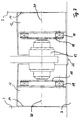
- FIG. 3 While the compaction roller shown in Figure 2 extend across the entire width of a road roller a variant is shown in FIG. 3, where the two cone-like from the outside to the center tapering compaction rollers according to the invention are recognizable. These are as in FIG. 2 shown in each case via elastic elements 19 corresponding coupling discs 18 attached, via the they are driven by the drive 13. Since the corresponding central axes 20 for both rollers are inclined at the top, the bottom 2 becomes flat overall condensed. But there remains one between the two Compaction rollers lying area 22 unprocessed. It is used by another, not shown here Compaction roller of the road roller post-compressed.
- end planes 14 of the two compaction rollers 12 are inclined inwards, one is suitable such roller combination, alternatively or at the same time a floor up to a left or right towering wall 3 to compress without the risk exists, with slight steering errors on this wall Cause damage.
Landscapes
- Engineering & Computer Science (AREA)
- Architecture (AREA)
- Civil Engineering (AREA)
- Structural Engineering (AREA)
- Road Paving Machines (AREA)
- Tyre Moulding (AREA)
- Rigid Containers With Two Or More Constituent Elements (AREA)
- Vibration Prevention Devices (AREA)
- Rollers For Roller Conveyors For Transfer (AREA)
- Supply Devices, Intensifiers, Converters, And Telemotors (AREA)
- Road Paving Structures (AREA)
- Friction Gearing (AREA)
- Liquid Crystal (AREA)
- Sheets, Magazines, And Separation Thereof (AREA)
Abstract
Description
- Figur 1
- Schnitt durch eine erfindungsgemaße Rolle als Anbauteil;
- Figur 2
- Schnitt durch eine erfindungsgemaße Rolle als Verdichtungswalze einer Straßenwalze und
- Figur 3
- Achse einer Straßenwalze mit zwei erfindungsgemäßen Verdichtungswalzen.
Claims (10)
- Vorrichtung zur Boden- und Asphaltverdichtung mit mindestens einer Rolle (5, 12), die eine sich von einer seitlich außenliegenden Stirnebene (6, 14) aus konusartig verjüngende Kontur hat,
dadurch gekennzeichnet,
daß die Stirnebene (6, 14) nach oben eine Neigung nach innen aufweist. - Vorrichtung gemäß Anspruch 1,
dadurch gekennzeichnet,
daß die Unterseite (8) der Rolle (5) im wesentlichen horizontal verläuft. - Vorrichtung gemäß Anspruch 1,
dadurch gekennzeichnet,
daß die Rolle (5) an einer Lagerung (9) befestigt ist, deren Achse (23) um den Neigungswinkel (11) der Stirnebene (6) nach oben geschwenkt ist. - Vorrichtung gemäß Anspruch 1,
dadurch gekennzeichnet,
daß die Rolle (12) über elastische Elemente (19) an eine Lagerung (13) mit horizontaler Achse (21) anschließbar ist. - Vorrichtung gemäß Anspruch 1,
dadurch gekennzeichnet,
daß die Rolle (12) einen parallel zur Stirnebene (14) verlaufenden Befestigungsflansch (17) aufweist. - Vorrichtung gemäß Anspruch 1,
dadurch gekennzeichnet,
daß die Rolle (5) an einem Kragarm (10) zur Befestigung eines Zusatzteil an einer Straßenwalze gelagert ist. - Vorrichtung gemäß Anspruch 1,
dadurch gekennzeichnet, daß die Rolle (12) eine Verdichtungswalze einer Straßenwalze ist. - Vorrichtung gemäß Anspruch 1,
dadurch gekennzeichnet,
daß die Rolle (12) eine im wesentlichen zylindrische Innenkontur und eine Mantelbandage (16) mit keilförmigen Querschnitt aufweist. - Vorrichtung gemäß Anspruch 1,
dadurch gekennzeichnet,
daß die Rolle statisch belastet wird. - Vorrichtung gemäß Anspruch 1,
dadurch gekennzeichnet,
daß die Rolle vibrierend belastet wird.
Priority Applications (1)
| Application Number | Priority Date | Filing Date | Title |
|---|---|---|---|
| DE29724634U DE29724634U1 (de) | 1996-07-30 | 1997-07-10 | Strassenwalze |
Applications Claiming Priority (2)
| Application Number | Priority Date | Filing Date | Title |
|---|---|---|---|
| DE19630576 | 1996-07-30 | ||
| DE19630576A DE19630576A1 (de) | 1996-07-30 | 1996-07-30 | Straßenwalze |
Publications (3)
| Publication Number | Publication Date |
|---|---|
| EP0822294A2 true EP0822294A2 (de) | 1998-02-04 |
| EP0822294A3 EP0822294A3 (de) | 1998-10-07 |
| EP0822294B1 EP0822294B1 (de) | 2003-05-21 |
Family
ID=7801183
Family Applications (1)
| Application Number | Title | Priority Date | Filing Date |
|---|---|---|---|
| EP97111735A Expired - Lifetime EP0822294B1 (de) | 1996-07-30 | 1997-07-10 | Strassenwalze |
Country Status (4)
| Country | Link |
|---|---|
| EP (1) | EP0822294B1 (de) |
| AT (1) | ATE241041T1 (de) |
| DE (2) | DE19630576A1 (de) |
| DK (1) | DK0822294T3 (de) |
Cited By (1)
| Publication number | Priority date | Publication date | Assignee | Title |
|---|---|---|---|---|
| DE102010008308A1 (de) * | 2010-02-17 | 2011-08-18 | BOMAG GmbH, 56154 | Kantenrichtvorrichtung |
Families Citing this family (1)
| Publication number | Priority date | Publication date | Assignee | Title |
|---|---|---|---|---|
| DE102015016627A1 (de) | 2015-12-21 | 2017-06-22 | Bomag Gmbh | Bodenverdichtungsbandage und Baumaschine zur Bodenverdichtung |
Family Cites Families (10)
| Publication number | Priority date | Publication date | Assignee | Title |
|---|---|---|---|---|
| FR465684A (fr) * | 1913-11-18 | 1914-04-22 | Pierre Cornus | Roues à compression variable obtenue par l'addition de produits naturels (eau, sable, matériaux, etc.) appliquées aux rouleaux compresseurs à traction mécanique |
| DE501095C (de) * | 1928-01-21 | 1930-06-27 | Gebhard Hasselmann Maschinenfa | Hubvorrichtung fuer ein zwischen Lenk- und Antriebswalzen einer Strassenwalze angeordnetes heb- und senkbares Walzenpaar |
| US2985079A (en) * | 1955-11-02 | 1961-05-23 | Donald H Clapper | Earth rollers |
| DE1459719A1 (de) * | 1964-09-22 | 1969-10-23 | Rheinstahl Henschel Ag | Strassenwalze,insbesondere Tandemwalze |
| DE2441229C2 (de) * | 1969-02-08 | 1985-11-14 | Hoffmann, geb. Eisler, Elisabeth, 6670 St Ingbert | Vorrichtung für eine Andrückwalze zum Verdichten von Straßenrändern |
| DE2061966C3 (de) * | 1969-02-08 | 1981-10-15 | Hoffmann, geb. Eisler, Elisabeth, 6670 St Ingbert | An eine Straßenwalze anbaubare Kantenandrückwalze zum Verdichten von Straßenrändern |
| DE2927883A1 (de) * | 1979-07-11 | 1981-01-29 | Hoffmann Geb Eisler Elisabeth | An einer strassenwalze anbaubares arbeitsgeraet zum bearbeiten von strassenraendern |
| DE8710179U1 (de) * | 1987-07-24 | 1987-09-17 | Bomag-Menck GmbH, 5407 Boppard | Vibrationskantenrolle |
| DE8811755U1 (de) * | 1988-09-16 | 1988-11-10 | Silo-Wolff KG, 3471 Lauenförde | Packerwalze |
| DE29508563U1 (de) * | 1995-05-23 | 1996-01-25 | KSG Kantenstampf- und Schneidegeräte Handelsgesellschaft mbH, 66386 St Ingbert | An eine Straßenwalze anbaubares Arbeitsgerät zum Bearbeiten von Straßenrändern |
-
1996
- 1996-07-30 DE DE19630576A patent/DE19630576A1/de not_active Withdrawn
-
1997
- 1997-07-10 EP EP97111735A patent/EP0822294B1/de not_active Expired - Lifetime
- 1997-07-10 DK DK97111735T patent/DK0822294T3/da active
- 1997-07-10 AT AT97111735T patent/ATE241041T1/de not_active IP Right Cessation
- 1997-07-10 DE DE59710109T patent/DE59710109D1/de not_active Expired - Fee Related
Cited By (1)
| Publication number | Priority date | Publication date | Assignee | Title |
|---|---|---|---|---|
| DE102010008308A1 (de) * | 2010-02-17 | 2011-08-18 | BOMAG GmbH, 56154 | Kantenrichtvorrichtung |
Also Published As
| Publication number | Publication date |
|---|---|
| DE59710109D1 (de) | 2003-06-26 |
| EP0822294A3 (de) | 1998-10-07 |
| DE19630576A1 (de) | 1998-02-05 |
| ATE241041T1 (de) | 2003-06-15 |
| DK0822294T3 (da) | 2003-09-15 |
| EP0822294B1 (de) | 2003-05-21 |
Similar Documents
| Publication | Publication Date | Title |
|---|---|---|
| DE60121390T2 (de) | Vibrationswalze | |
| DE102010035131A1 (de) | Vorrichtung zur gelenkigen Verbindung von zwei Fahrzeugrahmen einer Baumaschine | |
| DE1954867A1 (de) | Vibrator-Einheit | |
| EP2381037B1 (de) | Selbstnivellierender Schachtabdeckungsrahmen | |
| DE3311019C2 (de) | Gleitschuh | |
| WO2019179705A1 (de) | Verfahren und vorrichtung zur ausschalung einer tunnelröhre | |
| DE3431750C2 (de) | ||
| EP0822294B1 (de) | Strassenwalze | |
| EP2789747B1 (de) | Baumaschine zur Bodenverdichtung | |
| DE69132127T2 (de) | Rohrverbindung | |
| DE8710179U1 (de) | Vibrationskantenrolle | |
| DE9420809U1 (de) | Gummielastische Profilleiste | |
| DE8434059U1 (de) | Strassenkehr-sammelmaschine mit einem in bezug auf den erdboden in der hoehe verstellbaren hubfoerderer | |
| DE29724634U1 (de) | Strassenwalze | |
| DE4122155C2 (de) | Vorrichtung an Transportfahrzeugen zum Transport von großen, einstückigen Lasten | |
| DE69503752T2 (de) | Drehgestell für fahrzeugantriebsrad und hydraulisch angetriebene laufrolle für ein solches drehgestell | |
| DE19719142A1 (de) | Straßenwalze | |
| DE2949628A1 (de) | Brems- und sicherungsvorrichtung fuer lastfahrzeuge | |
| EP2158364B1 (de) | Fahrzeugrückhaltesystem zum absichern von fahrbahnen mit einem passagebereich | |
| EP2439332A1 (de) | Vibrationsstampfer mit Stampferfuss | |
| EP1935834A1 (de) | Teleskopschuss | |
| EP1029981A1 (de) | Selbstfahrende Verdichtungsvorrichtung zur Bodenverdichtung | |
| DE4446225A1 (de) | Dreiradschlepperfahrzeug | |
| EP2886716A1 (de) | Vorrichtung zur Herstellung eines Randstreifens einer Fahrbahnkonstruktion, Verfahren zur Herstellung eines solchen Randstreifens, aus Gussasphalt gebildeter Randstreifen und Verfahren zur Herstellung einer Fahrbahnkonstruktion | |
| DE2851880A1 (de) | Fahrzeug |
Legal Events
| Date | Code | Title | Description |
|---|---|---|---|
| PUAI | Public reference made under article 153(3) epc to a published international application that has entered the european phase |
Free format text: ORIGINAL CODE: 0009012 |
|
| AK | Designated contracting states |
Kind code of ref document: A2 Designated state(s): AT BE CH DE DK ES FI FR GB IT LI NL SE |
|
| PUAL | Search report despatched |
Free format text: ORIGINAL CODE: 0009013 |
|
| AK | Designated contracting states |
Kind code of ref document: A3 Designated state(s): AT BE CH DE DK ES FI FR GB GR IE IT LI LU MC NL PT SE |
|
| 17P | Request for examination filed |
Effective date: 19981021 |
|
| AKX | Designation fees paid |
Free format text: AT BE CH DE DK ES FI FR GB IT LI NL SE |
|
| 17Q | First examination report despatched |
Effective date: 20011018 |
|
| GRAH | Despatch of communication of intention to grant a patent |
Free format text: ORIGINAL CODE: EPIDOS IGRA |
|
| GRAH | Despatch of communication of intention to grant a patent |
Free format text: ORIGINAL CODE: EPIDOS IGRA |
|
| GRAA | (expected) grant |
Free format text: ORIGINAL CODE: 0009210 |
|
| AK | Designated contracting states |
Designated state(s): AT BE CH DE DK ES FI FR GB IT LI NL SE |
|
| PG25 | Lapsed in a contracting state [announced via postgrant information from national office to epo] |
Ref country code: NL Free format text: LAPSE BECAUSE OF FAILURE TO SUBMIT A TRANSLATION OF THE DESCRIPTION OR TO PAY THE FEE WITHIN THE PRESCRIBED TIME-LIMIT Effective date: 20030521 Ref country code: FI Free format text: LAPSE BECAUSE OF FAILURE TO SUBMIT A TRANSLATION OF THE DESCRIPTION OR TO PAY THE FEE WITHIN THE PRESCRIBED TIME-LIMIT Effective date: 20030521 |
|
| REG | Reference to a national code |
Ref country code: GB Ref legal event code: FG4D Free format text: NOT ENGLISH |
|
| REG | Reference to a national code |
Ref country code: CH Ref legal event code: EP |
|
| REG | Reference to a national code |
Ref country code: CH Ref legal event code: NV Representative=s name: RITSCHER & PARTNER AG PATENTANWAELTE |
|
| REF | Corresponds to: |
Ref document number: 59710109 Country of ref document: DE Date of ref document: 20030626 Kind code of ref document: P |
|
| GBT | Gb: translation of ep patent filed (gb section 77(6)(a)/1977) | ||
| PG25 | Lapsed in a contracting state [announced via postgrant information from national office to epo] |
Ref country code: BE Free format text: LAPSE BECAUSE OF NON-PAYMENT OF DUE FEES Effective date: 20030731 |
|
| PG25 | Lapsed in a contracting state [announced via postgrant information from national office to epo] |
Ref country code: SE Free format text: LAPSE BECAUSE OF FAILURE TO SUBMIT A TRANSLATION OF THE DESCRIPTION OR TO PAY THE FEE WITHIN THE PRESCRIBED TIME-LIMIT Effective date: 20030821 |
|
| PG25 | Lapsed in a contracting state [announced via postgrant information from national office to epo] |
Ref country code: ES Free format text: LAPSE BECAUSE OF FAILURE TO SUBMIT A TRANSLATION OF THE DESCRIPTION OR TO PAY THE FEE WITHIN THE PRESCRIBED TIME-LIMIT Effective date: 20030901 |
|
| REG | Reference to a national code |
Ref country code: DK Ref legal event code: T3 |
|
| NLV1 | Nl: lapsed or annulled due to failure to fulfill the requirements of art. 29p and 29m of the patents act | ||
| ET | Fr: translation filed | ||
| BERE | Be: lapsed |
Owner name: *BOMAG G.M.B.H. Effective date: 20030731 |
|
| PLBE | No opposition filed within time limit |
Free format text: ORIGINAL CODE: 0009261 |
|
| 26N | No opposition filed |
Effective date: 20040224 |
|
| PGFP | Annual fee paid to national office [announced via postgrant information from national office to epo] |
Ref country code: DK Payment date: 20080929 Year of fee payment: 12 Ref country code: CH Payment date: 20081229 Year of fee payment: 12 |
|
| PGFP | Annual fee paid to national office [announced via postgrant information from national office to epo] |
Ref country code: AT Payment date: 20090102 Year of fee payment: 12 |
|
| PGFP | Annual fee paid to national office [announced via postgrant information from national office to epo] |
Ref country code: DE Payment date: 20090112 Year of fee payment: 12 |
|
| PGFP | Annual fee paid to national office [announced via postgrant information from national office to epo] |
Ref country code: GB Payment date: 20081229 Year of fee payment: 12 |
|
| PGFP | Annual fee paid to national office [announced via postgrant information from national office to epo] |
Ref country code: IT Payment date: 20090119 Year of fee payment: 12 |
|
| PGFP | Annual fee paid to national office [announced via postgrant information from national office to epo] |
Ref country code: FR Payment date: 20081230 Year of fee payment: 12 |
|
| REG | Reference to a national code |
Ref country code: CH Ref legal event code: PL |
|
| REG | Reference to a national code |
Ref country code: DK Ref legal event code: EBP |
|
| GBPC | Gb: european patent ceased through non-payment of renewal fee |
Effective date: 20090710 |
|
| REG | Reference to a national code |
Ref country code: FR Ref legal event code: ST Effective date: 20100331 |
|
| PG25 | Lapsed in a contracting state [announced via postgrant information from national office to epo] |
Ref country code: LI Free format text: LAPSE BECAUSE OF NON-PAYMENT OF DUE FEES Effective date: 20090731 Ref country code: FR Free format text: LAPSE BECAUSE OF NON-PAYMENT OF DUE FEES Effective date: 20090731 Ref country code: CH Free format text: LAPSE BECAUSE OF NON-PAYMENT OF DUE FEES Effective date: 20090731 |
|
| PG25 | Lapsed in a contracting state [announced via postgrant information from national office to epo] |
Ref country code: GB Free format text: LAPSE BECAUSE OF NON-PAYMENT OF DUE FEES Effective date: 20090710 |
|
| PG25 | Lapsed in a contracting state [announced via postgrant information from national office to epo] |
Ref country code: DE Free format text: LAPSE BECAUSE OF NON-PAYMENT OF DUE FEES Effective date: 20100202 Ref country code: AT Free format text: LAPSE BECAUSE OF NON-PAYMENT OF DUE FEES Effective date: 20090710 |
|
| PG25 | Lapsed in a contracting state [announced via postgrant information from national office to epo] |
Ref country code: DK Free format text: LAPSE BECAUSE OF NON-PAYMENT OF DUE FEES Effective date: 20090731 |
|
| PG25 | Lapsed in a contracting state [announced via postgrant information from national office to epo] |
Ref country code: IT Free format text: LAPSE BECAUSE OF NON-PAYMENT OF DUE FEES Effective date: 20090710 |