EP0822295A1 - Ausrüstung für die schaffung einer drainage mit verstärkung weichen bodens, und verfahren und einrichtung zur anordnung der drainage - Google Patents
Ausrüstung für die schaffung einer drainage mit verstärkung weichen bodens, und verfahren und einrichtung zur anordnung der drainage Download PDFInfo
- Publication number
- EP0822295A1 EP0822295A1 EP96909391A EP96909391A EP0822295A1 EP 0822295 A1 EP0822295 A1 EP 0822295A1 EP 96909391 A EP96909391 A EP 96909391A EP 96909391 A EP96909391 A EP 96909391A EP 0822295 A1 EP0822295 A1 EP 0822295A1
- Authority
- EP
- European Patent Office
- Prior art keywords
- drain
- pack
- reinforcement
- soft ground
- guide
- Prior art date
- Legal status (The legal status is an assumption and is not a legal conclusion. Google has not performed a legal analysis and makes no representation as to the accuracy of the status listed.)
- Withdrawn
Links
- 238000000034 method Methods 0.000 title claims abstract description 21
- 230000003014 reinforcing effect Effects 0.000 title claims abstract description 17
- 230000002787 reinforcement Effects 0.000 claims abstract description 66
- 239000004576 sand Substances 0.000 claims description 35
- 230000001133 acceleration Effects 0.000 claims description 13
- 239000000463 material Substances 0.000 claims description 12
- 239000004020 conductor Substances 0.000 claims description 5
- 238000001746 injection moulding Methods 0.000 claims description 4
- 239000000835 fiber Substances 0.000 claims description 2
- XLYOFNOQVPJJNP-UHFFFAOYSA-N water Substances O XLYOFNOQVPJJNP-UHFFFAOYSA-N 0.000 claims description 2
- 230000000694 effects Effects 0.000 abstract description 7
- 230000015572 biosynthetic process Effects 0.000 abstract description 2
- 238000000465 moulding Methods 0.000 description 14
- 238000005452 bending Methods 0.000 description 7
- 238000010276 construction Methods 0.000 description 6
- 238000004519 manufacturing process Methods 0.000 description 4
- 229910000831 Steel Inorganic materials 0.000 description 2
- 238000005516 engineering process Methods 0.000 description 2
- 239000010959 steel Substances 0.000 description 2
- 239000003086 colorant Substances 0.000 description 1
- 230000007774 longterm Effects 0.000 description 1
- 238000002844 melting Methods 0.000 description 1
- 230000008018 melting Effects 0.000 description 1
- 239000002184 metal Substances 0.000 description 1
- 230000003204 osmotic effect Effects 0.000 description 1
- 239000002689 soil Substances 0.000 description 1
Images


Classifications
-
- E—FIXED CONSTRUCTIONS
- E02—HYDRAULIC ENGINEERING; FOUNDATIONS; SOIL SHIFTING
- E02D—FOUNDATIONS; EXCAVATIONS; EMBANKMENTS; UNDERGROUND OR UNDERWATER STRUCTURES
- E02D3/00—Improving or preserving soil or rock, e.g. preserving permafrost soil
- E02D3/02—Improving by compacting
- E02D3/08—Improving by compacting by inserting stones or lost bodies, e.g. compaction piles
-
- E—FIXED CONSTRUCTIONS
- E02—HYDRAULIC ENGINEERING; FOUNDATIONS; SOIL SHIFTING
- E02B—HYDRAULIC ENGINEERING
- E02B11/00—Drainage of soil, e.g. for agricultural purposes
-
- E—FIXED CONSTRUCTIONS
- E02—HYDRAULIC ENGINEERING; FOUNDATIONS; SOIL SHIFTING
- E02D—FOUNDATIONS; EXCAVATIONS; EMBANKMENTS; UNDERGROUND OR UNDERWATER STRUCTURES
- E02D3/00—Improving or preserving soil or rock, e.g. preserving permafrost soil
- E02D3/02—Improving by compacting
- E02D3/10—Improving by compacting by watering, draining, de-aerating or blasting, e.g. by installing sand or wick drains
Definitions
- the present invention relates to a technology of reinforcing soft grounds, and more particularly to a pack for molding a sand pile to form a drain, a pack guide casing for driving a pack underground, a pack file driving apparatus which is used for driving a pack into a guide casing, and a drain structure and an alignment method thereof.
- a vertical draining method such as a flexible sand drain and/or a paper drain is generally used for reinforcing a soft ground.
- a conventional vertical draining method drives a cylindrical guide casing underground, inserts a sand pack or a paper drain board into the guide casing, and then removes the guide casing.
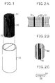
- FIG. 1 is a perspective view of a flexible sand pack and a guide casing which are used for a conventional vertical draining method. As shown in FIG. 1, the conventional vertical draining method is accomplished by burying a cylindrical guide casing 10 underground, and then inserting a sand pile molding pack 20 into guide casing 10.
- the pack 20 which comprises a mesh-type texture, is formed by overlapping two sheets of the mesh-type textures such that side portions of these sheets form reinforcement portions 31 and 32 extending lengthwise by connecting both ends or thermally melting them to attach to each other.
- Pack 20 inserted into guide casing 10 is filled with sand, and then guide casing 10 is removed at the sand-filled state to form a drain.
- the conventional sand pile molding pack has problems that the manufacturing method is complicated and the manufacturing cost is high. Also, the conventional molding packs are susceptible to breakage or cut-off, or some discrepancy between latitude and longitude. Further, the conventional pack has a problem that the reinforcement portion 31 or 32 is folded, such that a fine soil cannot pass, and a film is formed which lowers a draining effect. Also, since the conventional flexible drain is in a cylindrical shape and the diameter of the drain is limited to a range within 25cm, a draining contact area is small which lowers a draining effect.
- the conventional guide casing is formed as only a cylindrical shape, to accordingly raise a phenomenon of twisting the pack when the pack is inserted. Moreover, since the paper drain board is a structure of a thin plate when the paper drain is formed, many spaces are formed therein. Thus, removal of the casing causes an excessive ground movement.
- Another object of the present invention is to provide a sand pile molding pack comprising a reinforcement portion in which an electric conductor is incorporated.
- Yet another object of the present invention is to provide a polygonal sand pile molding pack.
- Still another object of the present invention is to provide a pack in which a flexible sand drain and a paper drain are simultaneously installed.
- Still yet another object of the present invention is to provide a pack guide member in which a pack is not twisted to each other.
- a further object of the present invention is to provide a drain including sand and a reinforcement member for draining acceleration that is buried in sand.
- a yet further object of the present invention is to provide a device for dropping a reinforcement member.
- a still further object of the present invention is to provide a guide casing which can prevent its bending when buried underground.
- a still yet further object of the present invention is to provide a casing comprising an internal reinforcement member.
- Yet another object of the present invention is to provide a drain structure and an arrangement method thereof in which a draining effect is high.
- Still yet another object of the present invention is to provide a pile driver for supplying a pack to be driven into a guide casing, so as to form a plurality of drains being in a rectangular shape.
- a pack which is used for reinforcing a soft ground according to an aspect of the present invention, wherein the pack is fabricated via an injection molding.
- a drain for reinforcing a soft ground comprises sand buried underground; and at least one or more reinforcement members for draining acceleration which is buried in the sand.
- a dropping device of reinforcement members comprises a casing, including space inside for receiving a reinforcement member for draining acceleration and forming a predetermined size of piercing holes at the top and bottom thereof; and a fastening member, disposed at the outer of the piercing holes of the casing, by which one end of the reinforcement portion is fastened.
- a guiding pack which is used for reinforcing a soft ground comprises a first member which is formed with a hollow shape of a polygonal body having a predetermined length; and a second member which is connected in the lower end of the pack and connected to the hollow inside of the first member, having the same angle as the first member, to be movable up and down.
- a guide casing for forming a drain which is used for reinforcing a soft ground comprises a body, formed in a hollow shape having a predetermined length; and at least one or more reinforcement members which protrudes in the body.
- a drain structure for reinforcing a soft ground is characterized by the fact that the drain structure is in a rectangular shape.
- a drain arrangement method for reinforcing a soft ground comprises the steps of maintaining a virtual line which connects a center line of each of four rectangular drains adjacent to each other to form a square, and arranging a longitudinal axis of each drain perpendicular to the longitudinal axis of an adjacent drain at the center.
- a driving apparatus for forming a drain according to a yet further feature of the present invention comprises:
- FIG. 1 is a perspective view of a conventional flexible pack and gide casing for explaining a vertical draining method.
- FIGs. 2A through 2C are views explaining a sand pile molding pack according to one embodiment of the present invention.
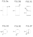
- FIGs. 3A through 3F are plan views of a sand pile molding pack according to another embodiment of the present invention.
- FIGs. 4A and 4B are perspective views of a drain according to embodiments of the present invention.
- FIGs. 5A and 5B are perspective views showing a weight material which is used for dropping a reinforcement member for draining acceleration when forming a drain
- FIG. 6 is a perspective view showing a dropping device of a reinforcement member for draining acceleration according to one embodiment of the present invention.
- FIG. 7 is a perspective view of a guide casing according to one embodiment of the present invention.
- FIG. 8 is a plan view of a guide casing according to another embodiment of the present invention.
- FIGs. 9A through 9D are plan views of guide casings according to yet another embodiment of the present invention.
- FIG. 10 is a plan view of a plurality of integrally constructed guide casings to embody a drain arranging method according to the present invention.
- FIG. 11 is a conceptual view for explaining a drain arranging method according to the present invention.
- FIG. 12A is a front view of a driving apparatus according to the present invention
- FIG. 12B is a cross-sectional view taken along a direction of I-I of FIG. 12A.
- FIG. 13A is a perspective view of a conventional flexible drain and FIG. 13B is a perspective view of a drain structure according to the present invention.
- FIGs. 2A through 2C are views explaining a sand pile molding pack according to one embodiment of the present invention.
- the pack of the present invention is fabricated by a metal injection molding method.
- FIG. 2A shows a sand pile molding pack material 50 having a reinforcement portion 51 at a constant interval which is obtained by the injection molding.
- a sand pile molding pack 60 shown in FIG. 2B is obtained by cutting pack material 50 of FIG. 2A to include at least one reinforcement portion 51 and combining the cut pack materials with each other.
- FIG. 2C is a cross-sectional view of a reinforcement portion of a sand pile molding pack according to another embodiment of the present invention.
- the reinforcement portion 51 in this embodiment includes an electric conductor 53 therein, which is for connecting an electrode when applying an electric osmotic method thereto.
- One electric conductor can be installed for every reinforcement portion 51 of pack 60, or a plurality of conductors can be separately installed in a single reinforcement portion.
- FIGs. 3A through 3F are plan views of sand pile molding packs according to yet another embodiments of the present invention. It can be seen that the packs of the present embodiments are extended lengthwise in the same pattern despite no showing perspective views.
- FIGs. 3A and 3C show rectangular packs and FIGs. 3D and 3F show cylindrical packs.
- the pack includes net portions 71 and a plurality of reinforcement portions 72.
- the reinforcement portion 72 can be attached to a sub-texture, and then the reinforcement portion 72 attached to the sub-texture is formed to have a bending portion for drain.
- the packs according to these embodiments have a merit that a flexible sand drain and a paper drain can be simultaneously formed.
- a draining area is 30% greater than a cylindrical pack which consumes the same amount of sand as that of the rectangular pack. That is, the rectangular pack has circumferential length of more than 30% at the same area compared with the cylindrical pack. Thus, an increased draining effect of more than 30% can be obtained, even though the same amount of sand is used.
- the conventional flexible pack is continuously produced without any marking in the same shape and color, and then is measured and cut by necessary lengths in use.
- the drain which is constructed by using such a pack has an exposed portion of the same shape and color.
- the pack of the present invention has markings which can identify the length of the pack. That is, when the pack is produced, various colors or figures are marked on the pack. Alternatively, reinforcement portions having the identified patterns are made and attached to the pack to advantageously permit the identification of the length by human vision.
- identification of the markings of the exposed drain can make a judgement of whether such a construction was properly done. Accordingly, poor construction can be prevented, and easy construction or effective construction control can be performed.
- FIGs. 4A and 4B are perspective views of a drain according to embodiments of the present invention.
- the drain of the present invention includes at least one or more reinforcement members 82 for draining acceleration at the inside of the sand drain 81.
- a drain board or a suction fiber of water can be used as a reinforcement member 82 for draining acceleration.
- this drain can expedite highly drain efficiency and maintain a certain operation for a long-term time, compared with the conventional paper drain or sand drain.
- FIGs. 5A and 5B are perspective views of a weight material which is used for dropping a reinforcement member for draining acceleration when forming a drain.
- the weight material is fabricated with a rigid material such as concrete, each of which forms a certain number of connectors 84 according to the number of the reinforcement member for draining acceleration. Connectors 84 are connected to the bottom of reinforcement member for draining acceleration.
- the weight materials can be varied according to a shape of the guide casing.
- Protrusions 86 of FIG. 5A are intended to drop a reinforcement member without occurrence of twist, which are coupled to a guide groove at the inside of the guide casing (not shown).
- FIG. 6 is a perspective view showing a dropping device of a reinforcement member for draining acceleration according to one embodiment of the present invention.
- a dropping unit includes a casing 87, at the top and bottom of which piercing holes 88 and 89 are respectively formed, and also forms a gate 90 capable of opening and shutting for putting in and out reinforcement members.
- a fastening member 91 is coupled to one end of reinforcement member 82 .
- Fastening member 91 which is disposed at the outer of the top piercing hole 88 of casing 87, is designed to have a predetermined size not to allow it to pass through piercing holes, and to form the drain by filling with sand after fixing the upper end of the reinforcement member to an inlet for sand.
- fastening member 91 is for combining the ends of reinforcement member 82, the member 91 does not depend on any specific shapes as well as format as shown in the drawing.
- the other end of reinforcement member 82 is connected to weight material 92 as shown in FIG. 5, so that reinforcement member 82 can be swiftly dropping into the inside of a casing for drain formation through the lower piercing hole 89 without any separate device.
- FIG. 7 is a perspective view of a guide casing according to one embodiment of the present invention.
- the casing of the present invention is driven by a predetermined depth into a soft ground and comprises a first member 95 having a polygonal body.
- the casing includes also a second member 96, which is connected to the bottom of pack P, for guiding swiftly pack P into the inside of first member 95.
- Second member 96 has the same angle as first member 95. Accordingly, when second member 96 is dropped into the inside of first member 95, the twist and distortion of pack P is prevented.
- FIG. 8 is a plan view of the guide casing according to another embodiment of the present invention.
- guide casing 100 in this embodiment is integrated with at least one or more reinforcement members 101.
- the reinforcement member 101 is for bending a paper drain board 102 and guiding it into the inside of casing 100 or preventing the bending of a casing. It is more preferable that paper drain board 102 is made of easily bendable materials at the portions which are shown as dotted lines.
- a wider drain board can be driven with a smaller cross-sectional area than in the linearly installed case. Accordingly, a draining effect is largely enhanced and the ground movement is reduced when driven.
- FIGs. 9A through 9D are plan views of guide casings according to different embodiments of the present invention.
- guide casings 110 in these embodiments have at least one outer protrusion 111, respectively.
- Such protrusions 111 are to prevent bending of guide casings 110 when guide casings 110 are buried underground, respectively.
- FIG. 9A is a plan view of guide casings 110 consisted of a H-type steel.
- an intermediate member of H-type steel plays a part of a reinforcement member 101.
- FIG. 10 is a plan view of the pack guide casings in which a plurality of the pack guide casings are simultaneously buried underground.
- a plurality of the pack guide casings 160 are mutually connected by first connectors 161.
- the dotted lines in the drawing represent second connectors 162 for effectively preventing the bending of the casing.
- FIG. 11 is a conceptual view for explaining a drain arranging method according to the present invention.
- the draining method according to the present invention has processes of maintaining a virtual line which connects a center point of each drain in four rectangular drains adjacent to each other to form a square, and of arranging a longitudinal axis of each drain perpendicular to the longitudinal axis of an adjacent drain at the center.
- an effective draining radius is balanced and a ground sink is also expedited since a draining interval is compact.
- FIG. 12A is a front view of a driving apparatus according to the present invention
- FIG. 12B is a cross-sectional view taken along a direction of I-I of FIG. 12A.
- the driving apparatus comprises a guide bar 170, which is vertically installed and to which a driving member 172 is combined.
- a driving block 173 is installed, to which an approximately rectangular shape of a holding plate 174 is fixed.
- a plurality of guide casings 175A ⁇ 175D are fixed, which are connected each other with a reinforcement connection plate 176, to thus prevent distortion of a casing and maintain its vertical state, thereby constructing a drain having the highest depth.
- a guide 177 is coupled to guide bar 170 and forms a hole that allows guide casings and reinforcement connection plate 176 to pass therethrough, and plays a role of guiding the direction when guide casings are buried underground. Therefore, at the upper end of holding plate 174 according to the driving apparatus, a device for providing sand or a drain board is optionally installed according to use purpose.
- FIG. 12B is a cross-sectional view taken along a direction of I-I of FIG. 12A.
- the driving apparatus of the present invention provides such a device which can drive simultaneously a plurality of drains according to the arrangement type of drains shown in FIG. 11.
- FIG. 13A is a perspective view of a conventional flexible drain.
- the flexible drain is in a cylindrical shape and the diameter of the cylindrical shape is limited to a the range between 5cm ⁇ 25cm.
- the reason why the size of the diameter is limited is a fact that normal draining is not attained if the diameter is less than 5cm, and the flexibility of the drain is inadequate if the diameter is greater than 25cm.
- FIG. 13B is a perspective view of a drain structure according to the present invention.
- the structure of the present invention is in a rectangular shape, in which the rectangular shape should have a length between 5cm and 25cm in both sides.
- the draining solves the inadequacy of the flexibility of the drain.
- the present invention provides effects that offers excellent draining, forms a drain with flexibility in horizontal and vertical directions, and increases a draining contact surface area with consumption of a small quantity of sand. That is, under the assumption of the same height in view of the size shown in the drawings, the drains of FIGs. 13A and 13B have nearly the same volume, but the FIG. 13B drain has much larger surface area in view of the circumferential length.
- the present invention provides a new type of technology for reinforcing a soft ground in which the conventional drawbacks are completely supplemented.
Landscapes
- Engineering & Computer Science (AREA)
- Life Sciences & Earth Sciences (AREA)
- Structural Engineering (AREA)
- General Engineering & Computer Science (AREA)
- Agronomy & Crop Science (AREA)
- Civil Engineering (AREA)
- Paleontology (AREA)
- Mining & Mineral Resources (AREA)
- General Life Sciences & Earth Sciences (AREA)
- Soil Sciences (AREA)
- Environmental & Geological Engineering (AREA)
- Mechanical Engineering (AREA)
- Investigation Of Foundation Soil And Reinforcement Of Foundation Soil By Compacting Or Drainage (AREA)
- Bulkheads Adapted To Foundation Construction (AREA)
- Non-Metallic Protective Coatings For Printed Circuits (AREA)
- Management, Administration, Business Operations System, And Electronic Commerce (AREA)
Applications Claiming Priority (5)
| Application Number | Priority Date | Filing Date | Title |
|---|---|---|---|
| KR19950008913 | 1995-04-15 | ||
| KR1995891 | 1995-04-15 | ||
| KR1019950011560A KR100209483B1 (ko) | 1995-05-11 | 1995-05-11 | 연속타설되는 드레인의 시공심도 확인방법 |
| KR1995115 | 1995-05-11 | ||
| PCT/KR1996/000054 WO1996033313A1 (en) | 1995-04-15 | 1996-04-15 | Drain forming equipment for reinforcing soft ground, and method and structure for arranging drains |
Publications (2)
| Publication Number | Publication Date |
|---|---|
| EP0822295A1 true EP0822295A1 (de) | 1998-02-04 |
| EP0822295A4 EP0822295A4 (de) | 1998-07-15 |
Family
ID=37027970
Family Applications (1)
| Application Number | Title | Priority Date | Filing Date |
|---|---|---|---|
| EP96909391A Withdrawn EP0822295A4 (de) | 1995-04-15 | 1996-04-15 | Ausrüstung für die schaffung einer drainage mit verstärkung weichen bodens, und verfahren und einrichtung zur anordnung der drainage |
Country Status (19)
| Country | Link |
|---|---|
| EP (1) | EP0822295A4 (de) |
| AP (1) | AP9701120A0 (de) |
| AR (1) | AR001630A1 (de) |
| AU (1) | AU5290196A (de) |
| BG (1) | BG101965A (de) |
| BR (1) | BR9608189A (de) |
| CA (1) | CA2218239A1 (de) |
| EA (1) | EA199700319A1 (de) |
| IL (1) | IL117890A0 (de) |
| NO (1) | NO974751L (de) |
| OA (1) | OA10524A (de) |
| PE (1) | PE29297A1 (de) |
| PL (1) | PL323155A1 (de) |
| SV (1) | SV1996000024A (de) |
| TN (1) | TNSN96060A1 (de) |
| TR (1) | TR199701175T1 (de) |
| TW (1) | TW303408B (de) |
| UY (1) | UY24205A1 (de) |
| WO (1) | WO1996033313A1 (de) |
Cited By (1)
| Publication number | Priority date | Publication date | Assignee | Title |
|---|---|---|---|---|
| ES2562841A1 (es) * | 2015-09-01 | 2016-03-08 | Universidad De Cantabria | Dispositivo y método de mejora de terreno blando |
Families Citing this family (1)
| Publication number | Priority date | Publication date | Assignee | Title |
|---|---|---|---|---|
| GB9713235D0 (en) * | 1997-06-23 | 1997-08-27 | Netlon Ltd | Electrically-conducting element |
Family Cites Families (21)
| Publication number | Priority date | Publication date | Assignee | Title |
|---|---|---|---|---|
| JPS4532743Y1 (de) * | 1966-04-13 | 1970-12-14 | ||
| GB1224646A (en) * | 1968-06-05 | 1971-03-10 | Cementation Co Ltd | Consolidation of soil and other water-permeable masses of similar grain size |
| JPS564683B2 (de) * | 1972-10-05 | 1981-01-31 | ||
| JPS4983813U (de) * | 1972-11-09 | 1974-07-19 | ||
| US3928979A (en) * | 1973-05-22 | 1975-12-30 | Chiyoda Chem Eng Construct Co | Flexible sand drain formed in a casing |
| JPS5120304U (de) * | 1974-08-01 | 1976-02-14 | ||
| JPS5128309A (ja) * | 1974-09-02 | 1976-03-10 | San Ando Shii Konsarutanto Kk | Sandodoreenkohonokeeshingudonyukokutsusakusochi |
| NL7501525A (nl) * | 1975-02-08 | 1976-08-10 | Akzo Nv | Werkwijze voor het vervaardigen van een steun- lichaam voor een weg, alsmede aldus vervaardigd steunlichaam. |
| JPS51149904U (de) * | 1975-05-27 | 1976-11-30 | ||
| JPS5428406A (en) * | 1977-08-05 | 1979-03-03 | Saeki Kensetsu Kogyo Kk | Method of placing drain material in weak ground |
| JPS54153105U (de) * | 1978-04-17 | 1979-10-24 | ||
| DE3267698D1 (en) * | 1982-02-05 | 1986-01-09 | Teijin Ltd | Method for improving soft ground by sand drain method and cylindrical bag for use in same |
| JPS6126730U (ja) * | 1984-07-23 | 1986-02-18 | 不動建設株式会社 | 被覆ドレ−ン杭造成用ケ−シング |
| JPS6149017A (ja) * | 1984-08-13 | 1986-03-10 | Toa Harbor Works Co Ltd | サンドドレ−ン工法 |
| JPS61135938U (de) * | 1985-02-08 | 1986-08-23 | ||
| JPS61186612A (ja) * | 1985-02-14 | 1986-08-20 | Tatsuo Morimoto | ドレインボ−ドの打込方法および打込装置 |
| JPS6327549U (de) * | 1986-08-04 | 1988-02-23 | ||
| US5037240A (en) * | 1990-07-19 | 1991-08-06 | Ocean Toad Enterprises Inc. | In-situ soil treatment process |
| GB2250762A (en) * | 1990-12-11 | 1992-06-17 | Graham Allan Feakins | Soil treatment |
| EP0499442B1 (de) * | 1991-02-11 | 1998-07-22 | Hepworth Building Products Limited | Untergrunddrainage |
| US5213449C1 (en) * | 1991-07-08 | 2001-07-03 | T Richard Morris | Apparatus for inserting wick drains into the earth |
-
1996
- 1996-04-12 IL IL11789096A patent/IL117890A0/xx unknown
- 1996-04-12 TW TW085104395A patent/TW303408B/zh active
- 1996-04-15 AP APAP/P/1997/001120A patent/AP9701120A0/en unknown
- 1996-04-15 SV SV1996000024A patent/SV1996000024A/es not_active Application Discontinuation
- 1996-04-15 EA EA199700319A patent/EA199700319A1/ru unknown
- 1996-04-15 UY UY24205A patent/UY24205A1/es not_active Application Discontinuation
- 1996-04-15 TN TNTNSN96060A patent/TNSN96060A1/fr unknown
- 1996-04-15 PL PL96323155A patent/PL323155A1/xx unknown
- 1996-04-15 TR TR97/01175T patent/TR199701175T1/xx unknown
- 1996-04-15 CA CA002218239A patent/CA2218239A1/en not_active Abandoned
- 1996-04-15 EP EP96909391A patent/EP0822295A4/de not_active Withdrawn
- 1996-04-15 AR AR33617796A patent/AR001630A1/es unknown
- 1996-04-15 BR BR9608189A patent/BR9608189A/pt not_active Application Discontinuation
- 1996-04-15 WO PCT/KR1996/000054 patent/WO1996033313A1/ja not_active Ceased
- 1996-04-15 PE PE1996000261A patent/PE29297A1/es not_active Application Discontinuation
- 1996-04-15 AU AU52901/96A patent/AU5290196A/en not_active Abandoned
-
1997
- 1997-10-14 OA OA70106A patent/OA10524A/en unknown
- 1997-10-14 NO NO974751A patent/NO974751L/no unknown
- 1997-10-15 BG BG101965A patent/BG101965A/xx unknown
Cited By (2)
| Publication number | Priority date | Publication date | Assignee | Title |
|---|---|---|---|---|
| ES2562841A1 (es) * | 2015-09-01 | 2016-03-08 | Universidad De Cantabria | Dispositivo y método de mejora de terreno blando |
| WO2017037309A1 (es) * | 2015-09-01 | 2017-03-09 | Universidad De Cantabria | Dispositivo y método de mejora de terreno blando |
Also Published As
| Publication number | Publication date |
|---|---|
| AP9701120A0 (en) | 1997-10-31 |
| EP0822295A4 (de) | 1998-07-15 |
| AR001630A1 (es) | 1997-11-26 |
| SV1996000024A (es) | 1997-10-15 |
| TNSN96060A1 (fr) | 1998-12-31 |
| NO974751D0 (no) | 1997-10-14 |
| WO1996033313A1 (en) | 1996-10-24 |
| TR199701175T1 (xx) | 1998-05-21 |
| BG101965A (en) | 1998-05-29 |
| CA2218239A1 (en) | 1996-10-24 |
| AU5290196A (en) | 1996-11-07 |
| PL323155A1 (en) | 1998-03-16 |
| EA199700319A1 (ru) | 1998-04-30 |
| MX9707903A (es) | 1997-11-29 |
| TW303408B (de) | 1997-04-21 |
| UY24205A1 (es) | 1996-05-14 |
| NO974751L (no) | 1997-12-12 |
| OA10524A (en) | 2002-04-29 |
| BR9608189A (pt) | 1999-05-04 |
| IL117890A0 (en) | 1997-04-15 |
| PE29297A1 (es) | 1997-09-12 |
Similar Documents
| Publication | Publication Date | Title |
|---|---|---|
| US5257880A (en) | Retaining wall construction and blocks therefor | |
| US5044834A (en) | Retaining wall construction and blocks therefor | |
| CA2463704C (en) | Wall block, system and method | |
| US6701687B1 (en) | Modular wall block with mechanical course connector | |
| CA2412591C (en) | Block retaining wall structure and setback locator therefor | |
| AU2002362879A1 (en) | Wall block, system and method | |
| WO1997035474B1 (en) | Liquid bait station | |
| US20040126186A1 (en) | Landscaping channel liner apparatus | |
| CA2218239A1 (en) | Drain forming equipment for reinforcing soft ground, and method and structure for arranging drains | |
| US5826395A (en) | Concrete block with offset ledge and installation guide means | |
| US20050081470A1 (en) | Block and block connector | |
| EP0747536A1 (de) | Drainagestruktur zum festigen von lockeren böden sowie verfahren und vorrichtung | |
| EP1675456B1 (de) | Vorrichtung zum abschrecken von vögeln | |
| EP1079024A3 (de) | Pflasterstein und daraus hergestelltes Muster | |
| KR100245047B1 (ko) | 연약지반 강화용 드레인 형성장비와 드레인 배열방법 및구조 | |
| CN1187228A (zh) | 加固软土地基用的排水桩的成型设备,以及排水桩的布置方法和结构 | |
| EP0804662B1 (de) | Gussform zum eingraben von rohren | |
| JP2787758B2 (ja) | 擁壁用ブロック | |
| CN216937586U (zh) | 等离子清洗机料盒 | |
| GB1580885A (en) | Noise barrier fencing | |
| MXPA97007903A (en) | Drainage training equipment to reinforce soft soils, as well as method and structure to fix drena | |
| JPH07233586A (ja) | 建設用ブロック | |
| JP3199485B2 (ja) | 土留杭保持枠 | |
| CN118360964A (zh) | 一种深基坑止水帷幕的施工方法及缠绕结构、钢塞模具 | |
| MXPA96005935A (es) | Estructura de drenaje de reforzamiento de suelo blando y metodo y aparato para instalarla |
Legal Events
| Date | Code | Title | Description |
|---|---|---|---|
| PUAI | Public reference made under article 153(3) epc to a published international application that has entered the european phase |
Free format text: ORIGINAL CODE: 0009012 |
|
| 17P | Request for examination filed |
Effective date: 19971027 |
|
| AK | Designated contracting states |
Kind code of ref document: A1 Designated state(s): BE DE DK ES FI FR GB GR IE IT LU MC NL PT SE |
|
| AX | Request for extension of the european patent |
Free format text: AL PAYMENT 971027;LT PAYMENT 971027;LV PAYMENT 971027;SI PAYMENT 971027 |
|
| A4 | Supplementary search report drawn up and despatched | ||
| AK | Designated contracting states |
Kind code of ref document: A4 Designated state(s): BE DE DK ES FI FR GB GR IE IT LU MC NL PT SE |
|
| STAA | Information on the status of an ep patent application or granted ep patent |
Free format text: STATUS: THE APPLICATION IS DEEMED TO BE WITHDRAWN |
|
| 18D | Application deemed to be withdrawn |
Effective date: 19991102 |