EP0822341A2 - Oleopneumatische Betätigungsvorrichtung für elektrische Schalter - Google Patents
Oleopneumatische Betätigungsvorrichtung für elektrische Schalter Download PDFInfo
- Publication number
- EP0822341A2 EP0822341A2 EP97111926A EP97111926A EP0822341A2 EP 0822341 A2 EP0822341 A2 EP 0822341A2 EP 97111926 A EP97111926 A EP 97111926A EP 97111926 A EP97111926 A EP 97111926A EP 0822341 A2 EP0822341 A2 EP 0822341A2
- Authority
- EP
- European Patent Office
- Prior art keywords
- piston
- pump
- microswitch
- pressure circuit
- cylinder
- Prior art date
- Legal status (The legal status is an assumption and is not a legal conclusion. Google has not performed a legal analysis and makes no representation as to the accuracy of the status listed.)
- Withdrawn
Links
- 239000012530 fluid Substances 0.000 claims abstract description 16
- 230000006835 compression Effects 0.000 claims abstract description 6
- 238000007906 compression Methods 0.000 claims abstract description 6
- 238000007599 discharging Methods 0.000 claims abstract description 5
- 230000000063 preceeding effect Effects 0.000 claims 1
- 239000007789 gas Substances 0.000 description 7
- IJGRMHOSHXDMSA-UHFFFAOYSA-N Atomic nitrogen Chemical compound N#N IJGRMHOSHXDMSA-UHFFFAOYSA-N 0.000 description 2
- 238000010276 construction Methods 0.000 description 2
- 230000000670 limiting effect Effects 0.000 description 2
- 229910000831 Steel Inorganic materials 0.000 description 1
- 230000003111 delayed effect Effects 0.000 description 1
- 230000001419 dependent effect Effects 0.000 description 1
- 239000002184 metal Substances 0.000 description 1
- 229910052757 nitrogen Inorganic materials 0.000 description 1
- 239000010959 steel Substances 0.000 description 1
Images

Classifications
-
- H—ELECTRICITY
- H01—ELECTRIC ELEMENTS
- H01H—ELECTRIC SWITCHES; RELAYS; SELECTORS; EMERGENCY PROTECTIVE DEVICES
- H01H33/00—High-tension or heavy-current switches with arc-extinguishing or arc-preventing means
- H01H33/02—Details
- H01H33/28—Power arrangements internal to the switch for operating the driving mechanism
- H01H33/30—Power arrangements internal to the switch for operating the driving mechanism using fluid actuator
-
- F—MECHANICAL ENGINEERING; LIGHTING; HEATING; WEAPONS; BLASTING
- F15—FLUID-PRESSURE ACTUATORS; HYDRAULICS OR PNEUMATICS IN GENERAL
- F15B—SYSTEMS ACTING BY MEANS OF FLUIDS IN GENERAL; FLUID-PRESSURE ACTUATORS, e.g. SERVOMOTORS; DETAILS OF FLUID-PRESSURE SYSTEMS, NOT OTHERWISE PROVIDED FOR
- F15B1/00—Installations or systems with accumulators; Supply reservoir or sump assemblies
- F15B1/02—Installations or systems with accumulators
- F15B1/027—Installations or systems with accumulators having accumulator charging devices
- F15B1/033—Installations or systems with accumulators having accumulator charging devices with electrical control means
Definitions
- the present invention relates to an oleo-pneumatic device or accumulator for actuating electric switches and more particularly a control system.
- Control means or actuators capable of supplying considerable amounts of mechanical energy in a very short time are required in various applications to actuate switches.
- Such energy must therefore be accumulated beforehand in devices which can be recharged slowly, i.e., with a small input of mechanical energy per unit time, and are then capable of quickly delivering this energy at the time of actuation.
- a well-known device of this kind comprises steel springs of various kinds which are loaded in various ways.
- Such a device has the fundamental drawback that its weight and bulk are very high as the energy to be accumulated increases.
- Another conventional device uses oleo-pneumatic accumulators which, for the same weight and bulk, allow to store much more energy than spring-loaded devices, typically 10 to 15 times more.
- the aim of the present invention is to overcome the above drawbacks of the prior art and particularly to provide an oleo-pneumatic device for actuating electric switches which has a simple construction and is capable of ensuring temperature-independence of the accumulated (and released) energy.
- an oleo-pneumatic device for actuating electric switches which comprises: a cylinder inside which a free piston can slide so as to define a chamber containing a working fluid; a pump for applying pressurized oil to the piston of the cylinder in order to compress the working fluid; control means for stopping the pump when the compressed fluid reaches a preset volume; and means for discharging the oil towards a low-pressure circuit in order to quickly release the stored energy; characterized in that said control means comprise an actuation microswitch for stopping the pump, whose position is a function of the temperature of the working fluid, and in that the microswitch cooperates with a profiled actuation element driven by the piston compression movement.
- the device according to the invention allows to precisely control the energy returned by an oleo-pneumatic accumulator in a temperature-independent manner and at the same time to provide a high-safety, high-precision control device.
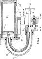
- the device according to the invention comprises a cylinder 1 which is closed by a bottom 22 at one end and by a head 3 at the other end.
- a free piston 2 can slide inside the cylinder 1 and defines, together with the bottom 22, a variable-volume chamber 24 containing a fluid (generally a gas, particularly nitrogen) in which the energy is stored.
- a fluid generally a gas, particularly nitrogen
- this energy depends on the pressure P and on the volume V and on the gas temperature.
- a union elbow 9 is fitted to the head 3; by means of the elbow, pressurized oil 21 can be applied to the surface of the piston 2 in order to compress the gas or can be discharged in order to use the energy stored in the compressed gas.
- the pressurized oil 21 arrives from a high-pressure circuit AP which comprises a pump 20 and a reservoir 29.
- a hole 25 is provided on the elbow 9 and a valve 8 is installed thereon; the valve comprises a T-shaped duct 26.
- a needle 11 can move axially in the horizontal arm of the T-shaped duct, which is aligned with the hole 25; the needle has a ball 10 at one end, whilst the other end of the needle protrudes from the body of the valve through an appropriate seal.
- the vertical arm of the T-shaped duct is connected by means of a tube 28 to a low-pressure circuit BP which is connected to a reservoir 29.
- the diameter of the hole 25 is smaller than the diameter of the ball 10, so that the ball obstructs the hole when the ball moves to the left.
- a rod 4 is directly and rigidly connected to the free piston 2 that separates the hydraulic circuit from the energy-accumulating volume of gas; the rod passes hermetically through the union elbow 9 and has, at its outer end, a slider 6 and a vane 7.
- the slider 6 is shaped like a profiled body and has the purpose of actuating a microswitch 5, which stops the pump 20 and is fitted on the head 3 by means of an elastic support 12 and an assembly consisting of a rigid support 14 and a thermostatic element 13.
- the microswitch 5 is provided with a contact 15 which is opened by the profile or inclined plane of the slider 6 when, during the compression movement, the piston 2 is moved forward by an extent c with respect to the maximum expansion position.
- the rigid supporting element 14 is shaped like a bracket which is fixed to the head 3 at one end by means of a screw and is in any case in thermal contact with the head and thus with the cylinder 1.
- the other end of the bracket 14 is fixed to the microswitch 5 by means of the thermostatic element 13, i.e., a temperature-sensitive component, for example a bimetallic strip.
- the microswitch 5 is rigidly coupled to the head 3 by means of the element 12, which is for example shaped like an elastic spring and applies a return force to the microswitch 5.
- the vertical position of the microswitch 5 is thus determined as a function of the temperature of the cylinder 1, i.e., of the temperature of the compressed gas. Accordingly, the opening of the contact 15 can be advanced or delayed as a function of the temperature both by acting on the adjustment of the thermostatic element 13 and by acting on the profile or inclined plane (or on the position) of the slider 6 or by acting on both.
- the vane 7 can move the needle to the right; more specifically, when the piston 2 under compression has covered a distance d , the vane 7 pushes the needle 11 of the valve 8 to the right and the ball connects the hole 25 to 21, thus allowing fluid hydraulic connection between the cylinder and the low-pressure circuit.
- the vane 7 discharges the excess pressure into the low-pressure circuit BP.
- the pump 29 for replenishing the circuit AP feeds pressurized oil into the cylinder 1, causing the movement of the piston 2, gradually reducing the volume of the chamber 24 and thus compressing the gas contained therein; the microswitch 5 stops the pump when a preset pressure is reached as a function of the temperature.
- the ball 10 is pushed so as to obstruct the duct 26 by the pressure of the oil 21 if the pump fails to stop.
- the vane 7 pushes the ball 10 to the right, allowing pressure limitation by discharging the oil through the valve 8 into the reservoir 29.
- the pressure P of the compressed fluid is a function of the stroke of the piston 2 and therefore of the stroke c , which in turn depends on the vertical position of the microswitch 5 determined by the temperature of the compressed fluid.
- the hydraulic circuit AP is preferably provided with the pressure limiting valve 8, which is connected to the reservoir 29 and opens if the pressure in the circuit AP exceeds a safety value.
- connection between the piston and an actuation rod 23 is provided by means of a traction element 16, i.e., an element capable of transmitting only traction forces but not compression forces, instead of by means of a rigid rod.
- the traction element 16 advantageously consists of a metal wire or chain.
- a curved duct 17 which covers an angle between 0 and 180 o , between the head 3 and a union 9 (similar to the union of figure 1) which is connected to the high-pressure circuit AP (not shown).
- the chain or wire rests against the inner surface of the curved duct.
Landscapes
- Engineering & Computer Science (AREA)
- Physics & Mathematics (AREA)
- Fluid Mechanics (AREA)
- Mechanical Engineering (AREA)
- General Engineering & Computer Science (AREA)
- Fluid-Pressure Circuits (AREA)
- Lighting Device Outwards From Vehicle And Optical Signal (AREA)
- Electrophonic Musical Instruments (AREA)
- Radiation-Therapy Devices (AREA)
Applications Claiming Priority (2)
| Application Number | Priority Date | Filing Date | Title |
|---|---|---|---|
| IT96MI001507A IT1283462B1 (it) | 1996-07-19 | 1996-07-19 | Dispositivo oleopneumatico per il comando di interruttori elettrici |
| ITMI961507 | 1996-07-19 |
Publications (2)
| Publication Number | Publication Date |
|---|---|
| EP0822341A2 true EP0822341A2 (de) | 1998-02-04 |
| EP0822341A3 EP0822341A3 (de) | 1999-04-07 |
Family
ID=11374620
Family Applications (1)
| Application Number | Title | Priority Date | Filing Date |
|---|---|---|---|
| EP97111926A Withdrawn EP0822341A3 (de) | 1996-07-19 | 1997-07-14 | Oleopneumatische Betätigungsvorrichtung für elektrische Schalter |
Country Status (2)
| Country | Link |
|---|---|
| EP (1) | EP0822341A3 (de) |
| IT (1) | IT1283462B1 (de) |
Cited By (2)
| Publication number | Priority date | Publication date | Assignee | Title |
|---|---|---|---|---|
| WO2002001076A3 (de) * | 2000-06-24 | 2002-07-18 | Bosch Gmbh Robert | Hydraulikenergiespeicher mit einem aus metall bestehenden faltenbalg |
| EP3503154A1 (de) * | 2017-12-19 | 2019-06-26 | E.G.O. ELEKTRO-GERÄTEBAU GmbH | Verfahren zum verändern eines arbeitsfluids in einem ausdehnungssystem und ausdehnungssystem |
Family Cites Families (5)
| Publication number | Priority date | Publication date | Assignee | Title |
|---|---|---|---|---|
| US2795932A (en) * | 1952-08-19 | 1957-06-18 | S & C Electric Co | Hydraulic actuating mechanism for operating electric circuit breakers and the like |
| DE1141193B (de) * | 1961-02-24 | 1962-12-13 | Daimler Benz Ag | Regelvorrichtung fuer eine Druckmittelanlage zum Betaetigen von verstellbaren Kraftfahrzeugteilen |
| CH654444A5 (fr) * | 1981-10-12 | 1986-02-14 | Alsthom Atlantique | Disjoncteur a gaz sous pression comprenant pour chaque phase deux chambres de coupure disposees en v. |
| FR2663780B1 (fr) * | 1990-06-26 | 1992-09-11 | Merlin Gerin | Disjoncteur haute tension a isolement gazeux et a mecanisme de commande pneumatique. |
| FR2750246B1 (fr) * | 1996-06-20 | 1998-09-04 | Gec Alsthom T & D Sa | Procede de surveillance d'un disjoncteur haute tension a circuit hydraulique de commande |
-
1996
- 1996-07-19 IT IT96MI001507A patent/IT1283462B1/it active IP Right Grant
-
1997
- 1997-07-14 EP EP97111926A patent/EP0822341A3/de not_active Withdrawn
Cited By (3)
| Publication number | Priority date | Publication date | Assignee | Title |
|---|---|---|---|---|
| WO2002001076A3 (de) * | 2000-06-24 | 2002-07-18 | Bosch Gmbh Robert | Hydraulikenergiespeicher mit einem aus metall bestehenden faltenbalg |
| EP3503154A1 (de) * | 2017-12-19 | 2019-06-26 | E.G.O. ELEKTRO-GERÄTEBAU GmbH | Verfahren zum verändern eines arbeitsfluids in einem ausdehnungssystem und ausdehnungssystem |
| US11761822B2 (en) | 2017-12-19 | 2023-09-19 | E.G.O. Elektro-Geraetebau Gmbh | Method for changing a working fluid in an expansion system, and expansion system |
Also Published As
| Publication number | Publication date |
|---|---|
| ITMI961507A0 (de) | 1996-07-19 |
| EP0822341A3 (de) | 1999-04-07 |
| IT1283462B1 (it) | 1998-04-21 |
| ITMI961507A1 (it) | 1998-01-19 |
Similar Documents
| Publication | Publication Date | Title |
|---|---|---|
| US7331767B2 (en) | Method of stepless capacity control of a reciprocating piston compressor and piston compressor with such control | |
| US3965317A (en) | Apparatus for indicating cylinder fluid level | |
| BR0304212A (pt) | Mola de pressão com comprimento ajustável | |
| US4187682A (en) | Constant pressure hydraulic accumulator | |
| JPH11270612A (ja) | 中間停止機能および温度補償能力を有するガススプリング | |
| US5103940A (en) | Self-adjusting brake incorporating wear compensation | |
| US4527580A (en) | Volume control device | |
| US5148834A (en) | Piston-type pressure accumulator for traction slip controlled brake systems and switching arrangement for same | |
| US5062616A (en) | Self-pumping hydropneumatic shock absorbing strut | |
| TWM567695U (zh) | 液壓工具及迴路 | |
| US6220026B1 (en) | Active control system | |
| EP0822341A2 (de) | Oleopneumatische Betätigungsvorrichtung für elektrische Schalter | |
| US4352644A (en) | Air-hydraulic pump | |
| US4299427A (en) | Adjusting arrangement for variable load valve device | |
| CA2108051A1 (en) | Hydraulic Pipeline Valve Operating System | |
| KR860001697B1 (ko) | 공압식 에너지 축적기가 달린 작동기 | |
| US2656745A (en) | Hydraulic system for riveting presses | |
| US11959529B1 (en) | Allow air springs to be self-charging | |
| US4108046A (en) | Liquid-gas constant force recoil spring | |
| US4870889A (en) | Hydraulic device for fuel pumping apparatus | |
| US2905432A (en) | Valves | |
| US3940937A (en) | Intensifier | |
| US4267767A (en) | Position lock | |
| US2917225A (en) | Capacity control for reciprocating compressors | |
| KR101028740B1 (ko) | 온도 감응형 액추에이터 |
Legal Events
| Date | Code | Title | Description |
|---|---|---|---|
| PUAI | Public reference made under article 153(3) epc to a published international application that has entered the european phase |
Free format text: ORIGINAL CODE: 0009012 |
|
| AK | Designated contracting states |
Kind code of ref document: A2 Designated state(s): DE FR IT |
|
| AX | Request for extension of the european patent |
Free format text: AL;LT;LV;RO;SI |
|
| PUAL | Search report despatched |
Free format text: ORIGINAL CODE: 0009013 |
|
| AK | Designated contracting states |
Kind code of ref document: A3 Designated state(s): AT BE CH DE DK ES FI FR GB GR IE IT LI LU MC NL PT SE |
|
| AX | Request for extension of the european patent |
Free format text: AL;LT;LV;RO;SI |
|
| RHK1 | Main classification (correction) |
Ipc: F15B 1/033 |
|
| 17P | Request for examination filed |
Effective date: 19990928 |
|
| AKX | Designation fees paid |
Free format text: DE FR IT |
|
| STAA | Information on the status of an ep patent application or granted ep patent |
Free format text: STATUS: THE APPLICATION IS DEEMED TO BE WITHDRAWN |
|
| 18D | Application deemed to be withdrawn |
Effective date: 20020201 |