EP0822350A2 - Schmierung für eine Nasskupplung - Google Patents
Schmierung für eine Nasskupplung Download PDFInfo
- Publication number
- EP0822350A2 EP0822350A2 EP97110506A EP97110506A EP0822350A2 EP 0822350 A2 EP0822350 A2 EP 0822350A2 EP 97110506 A EP97110506 A EP 97110506A EP 97110506 A EP97110506 A EP 97110506A EP 0822350 A2 EP0822350 A2 EP 0822350A2
- Authority
- EP
- European Patent Office
- Prior art keywords
- lubricant
- diameter side
- frictional engagement
- side member
- outer diameter
- Prior art date
- Legal status (The legal status is an assumption and is not a legal conclusion. Google has not performed a legal analysis and makes no representation as to the accuracy of the status listed.)
- Granted
Links
Images




Classifications
-
- F—MECHANICAL ENGINEERING; LIGHTING; HEATING; WEAPONS; BLASTING
- F16—ENGINEERING ELEMENTS AND UNITS; GENERAL MEASURES FOR PRODUCING AND MAINTAINING EFFECTIVE FUNCTIONING OF MACHINES OR INSTALLATIONS; THERMAL INSULATION IN GENERAL
- F16D—COUPLINGS FOR TRANSMITTING ROTATION; CLUTCHES; BRAKES
- F16D25/00—Fluid-actuated clutches
- F16D25/12—Details not specific to one of the before-mentioned types
- F16D25/123—Details not specific to one of the before-mentioned types in view of cooling and lubrication
-
- F—MECHANICAL ENGINEERING; LIGHTING; HEATING; WEAPONS; BLASTING
- F16—ENGINEERING ELEMENTS AND UNITS; GENERAL MEASURES FOR PRODUCING AND MAINTAINING EFFECTIVE FUNCTIONING OF MACHINES OR INSTALLATIONS; THERMAL INSULATION IN GENERAL
- F16D—COUPLINGS FOR TRANSMITTING ROTATION; CLUTCHES; BRAKES
- F16D25/00—Fluid-actuated clutches
- F16D25/06—Fluid-actuated clutches in which the fluid actuates a piston incorporated in, i.e. rotating with the clutch
- F16D25/062—Fluid-actuated clutches in which the fluid actuates a piston incorporated in, i.e. rotating with the clutch the clutch having friction surfaces
- F16D25/063—Fluid-actuated clutches in which the fluid actuates a piston incorporated in, i.e. rotating with the clutch the clutch having friction surfaces with clutch members exclusively moving axially
- F16D25/0635—Fluid-actuated clutches in which the fluid actuates a piston incorporated in, i.e. rotating with the clutch the clutch having friction surfaces with clutch members exclusively moving axially with flat friction surfaces, e.g. discs
- F16D25/0638—Fluid-actuated clutches in which the fluid actuates a piston incorporated in, i.e. rotating with the clutch the clutch having friction surfaces with clutch members exclusively moving axially with flat friction surfaces, e.g. discs with more than two discs, e.g. multiple lamellae
Definitions
- This invention relates to a lubricating structure for a wet-type clutch.
- a clutch for selectively bringing a frictional engagement element fitted to an inner diameter side of an outer diameter side member into frictional engagement with a frictional engagement element fitted to an outer diameter side of an inner diameter side member is known in order to selectively engage the outer diameter side member and the inner diameter side member spaced apart from each other in a radial direction and rotating relative to each other.
- Japanese Unexamined Patent Publication (Kokai) No. 4-258528 discloses the construction wherein a plurality of lubricant feed holes are formed in an inner diameter side member, a plurality of lubricant discharge holes are formed in an outer diameter side member and the lubricant is supplied to frictional engagement elements from the inner diameter side of the inner diameter side member through the lubricant feed holes and discharged from the lubricant discharge holes.
- a lubricant reservoir is formed on the inner diameter side of an outer diameter side member in such a manner as to dip frictional engagement elements into the lubricant, a plurality of lubricant feed holes are disposed in an inner diameter side member and the lubricant is supplied from the inner diameter side of the inner diameter side member to the frictional engagement elements inside the lubricant reservoir through the lubricant feed holes.
- the present invention is directed to provide a lubrication structure for a wet-type clutch capable of sufficiently cooling the friction surfaces of frictional engagement elements by a smaller quantity of a lubricant.
- a lubricating structure for a wet-type clutch including frictional engagement elements fitted respectively to an outer diameter side member and an inner diameter side member disposed in a spaced-apart relation and rotating relative to each other around a common axis, selectively pushed by push means between the outer diameter side member and the inner diameter side member, and brought into frictional engagement with each other.
- the lubricating structure comprises, a lubricant reservoir formed on the inner diameter side of the outer diameter side member in such a manner as to dip the friction surfaces of the frictional engagement elements into the lubricant, a lubricant feed oil passage connected to the lubricant reservoir on the more outer diameter side than the friction surfaces of the frictional engagement elements, and rotating with the outer diameter side member, lubricant introduction means for introducing the lubricant into the lubricant feed oil passage, and a discharge opening portion for discharging the lubricant from the lubricant reservoir.
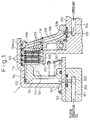
- Fig. 1 shows the construction of the first embodiment of the present invention.
- This drawing shows an input shaft 100 which normally rotates, and a wet type multiple disc clutch 1 which selectively engages this input shaft 100 with an output shaft 200.
- a first outer shell support disc 101 is fitted to the input shaft 100 by welding, and a cylindrical outer shell 102 extending from the outer diameter portion of the first outer shell support disc 101 in an axial direction is formed integrally with this first outer shell support disc 101.
- an inner shell support disc 201 is formed integrally with the output shaft 200, and a cylindrical inner shell 202 extending from the outer diameter portion of the inner shell support disc 201 in the axial direction is formed integrally with the inner shell support disc 201.
- Separator plates 103 and 103a are spline-coupled with the inner diameter side of the outer shell 102, and a clutch disc 203 is spline-coupled with the outer diameter side of the inner shell 202.
- a friction material 223 made of a paper-type material, for example, is bonded to each surface of a metallic base plate 213 spline-coupled with the inner shell 202, and oil grooves 233 are defined on the outer surface of the friction material 223.
- Reference numeral 104 denotes a piston.
- a piston operation oil is supplied to a piston oil chamber 105, the piston 104 moves to the right in the drawing against the force of a return spring 106, and engages the clutch discs 203 with the separator plates 103 and 103a.
- the piston operation oil is supplied through oil holes 301 and 302 bored in an input shaft support member 300 which does not rotate, and through an oil hole 107 bored in the input shaft 100.
- a second outer shell support disc 108 is fixedly coupled with the right end portion of the outer shell 102 in the drawing in such a manner as to integrally rotate with the outer shell 102, and the inner diameter side end face of this second outer shell support disc 108 comes into sliding contact with the outer peripheral surface of the output disc 200.
- a lubricant feed oil passage 109 extending in a radial direction is formed inside the second outer shell support disc 108.
- the lubricant feed oil passage 109 extends between an inlet opening 109a formed on the inner diameter side end face which comes into sliding contact with the outer peripheral surface of the output shaft 200, that is, the portion on the more outer diameter side than the end portion of the friction material 223 of the clutch disc 203, and an output opening 109b so formed as to open towards the side surface coming into contact with the inner surface of the outer shell 102 and the separator plate 103a.
- Reference numeral 110 represented by a dashed line denotes a lubricant discharge oil passage for discharging the lubricant after lubricating the surface of the friction material 223, and its position in the radial direction is more inwards than the end portion of the friction material 223 of the clutch disc 203 on the inner diameter side.
- a lubricant reservoir 111 is partitioned and defined by the outer shell 102, the separator plate 103a, the piston 104 and the second outer shell support disc 108 on the inner diameter side of the outer shell 102 so that the engagement portions between the separator plates 103 and 103a and the clutch disc 203 are dipped into the lubricant.
- the piston operation oil is introduced into the piston oil chamber 105 as represented by a thin arrow in Fig. 1, and the separator plates 103 and 103a are shown brought into the frictional engagement with the clutch discs 203.
- a thick arrow represents the flow of the lubricant.
- the lubricant flows from the oil hole 204 into the inner diameter side portion of the lubricant feed oil passage 109 through the oil hole 205 and the inlet opening 109a.
- the second outer shell support disc 108 is coupled with the input shaft 100 through the outer shell 102 and the first outer shell support disc 101, and rotates normally.
- the lubricant flowing into the inner diameter side portion of the lubricant feed oil passage 109 is sent out towards the outer diameter side by the centrifugal force in addition to the lubricant pressure, passes through an oil passage 112 formed by cutting off the outer diameter side end portion of the separator plates 103a from the outlet opening 109b, and is pressure-fed into the lubricant reservoir 111.
- the lubricant so introduced into the lubricant reservoir 111 gradually moves from the outer diameter side to the inner diameter side inside the lubricant reservoir 111, lubricates the surface of the friction material 223 of the clutch disc 203, flows through the oil grooves 233 and is discharged from the opening of the lubricant reservoir 111 through the lubricant discharge oil passage 110.
- the lubricant reliably moves inside the lubricant reservoir 111 from the engagement portions between the separator plates 103 and 103a and the clutch disc 203 from the outer peripheral side towards the opening of the lubricant reservoir 111. Therefore, the lubricant can always be supplied sufficiently to the engagement portions between the separator plates 103, 103a and the clutch disc 203 and the heat generated at these engagement portions can be reliably removed, and the engagement portions can be cooled satisfactorily.
- the lubricant inside the lubricant reservoir 111 is represented by the embossed portion.
- Fig. 3 shows the construction of the second embodiment.
- this second embodiment is different in that the first outer shell support disc 101 is made thicker, the lubricant feed oil passage 109 is formed in this disc 101, and only the lubricant discharge oil passage 110 is formed in the second outer shell support disc 108. Since the rest of the construction is fundamentally the same as that of the first embodiment, an explanation will be omitted.
- the flow of the lubricant in the engagement state and the lubricant inside the lubricant reservoir 111 are represented by the arrow and the embossed portion, respectively, in the same way as in Fig. 1.
- the lubricant is supplied to the lubricant feed oil passage 109 from the oil passages 303 and 304 formed in the input shaft support member 300 through the oil hole 115 bored in the input shaft 100. Therefore, the oil passages can be concentratedly formed in the input shaft support member 300 which does not rotate, and need not be formed in the output shaft 200.
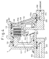
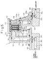
- the fourth embodiment has the following construction in addition to the construction of the first embodiment, as shown in Figs. 4 and 5.
- the outer shell 102 is provided with a lubricant discharge port 120 which is closed when the piston operation oil is supplied into the piston oil chamber 105 in association with the movement of the piston 104 in the axial direction, and which is opened when the piston operation oil is not supplied to the piston oil chamber 105 and the piston 104 is moved towards the first outer shell support disc 101, that is, when the separator plates 103 and 103a and the clutch disc 203 are out of the engagement state.
- the lubricant flowing out from the lubricant discharge port 120 has a smaller resistance than the lubricant flowing out from the lubricant discharge oil passage 110 through the gaps between the separator plates 103 and 103a and the clutch disc 203, and it is therefore discharged from the lubricant discharge port 120 (refer to the arrow in Fig. 5).
- the dragging torque of the clutch 1 at the time of disengagement becomes smaller, the power loss decreases, and the fuel cost can be reduced.
- the piston 104 moves to the right in the drawing and closes the lubricant discharge port 120 as shown in Fig. 6, so that the operation is entirely the same as that of the first embodiment.
- this fourth embodiment disposes a wave spring 130 between the separator plate 103a and the second outer shell support disc 108, and disposes also a lubricant discharge port 132, between the outer shell 102 and the separator plate 103a, which port opens when the separator plates 103 and 103a are out of engagement from the clutch disc 203 and which discharges the lubricant inside the lubricant reservoir 111 and the lubricant sent from the oil passage 112 through the lubricant feed oil passage 109 to the gap 131 defined between the separator plate 103a and the second outer shell support disc 108, as shown in Figs. 6 and 7.
- the second outer shell support disc 108 and the separator plate 103a are separated from each other by the wave spring 130 so that the gap 131 defined between the second outer shell support disc 108 and the separator plate 103a is communicated with the lubricant reservoir 111 through the lubricant discharge port 132.
- the gap 131 is formed in the second outer shell support disc 108, and communicates with the lubricant discharge oil passage 110 used for the discharge of the lubricant at the time of engagement, too.
- the lubricant discharge oil passage 110 is disposed immediately on the inner diameter side of the wave spring 130.
- the lubricant inside the lubricant reservoir 111 and the lubricant sent out from the lubricant feed oil passage 109 through the oil passage 112 do not flow from the lubricant discharge oil passage 110 through the gap between the separator plates 103 and 103a and the clutch disc 203 but flow through the passage described above having a smaller resistance, that is, through the lubricant discharge port 132, and through the gap 131 from the lubricant discharge oil passage 110 (refer to the arrow in Fig. 6).
- the wave spring 130 is flattened, so that the lubricant discharge port 132 is closed as shown in Fig. 9, and the lubricant inside the lubricant reservoir 111 flows from the opening of the lubricant reservoir 111 through the oil grooves 223 of the frictional material 223 of the clutch disc 203 and then through the gap 131 towards the outer diameter side, and is discharged from the lubricant discharge oil passage 110 (refer to the arrow in Fig. 7).
- Fig. 8 is a sectional view taken along a line XIII-XIII of Fig. 6 and shows the state of the wave spring 130 at the time of disengagement
- Fig. 9 is a sectional view taken along a line IX-IX of Fig. 7 and shows the state of the wave spring 130 at the time of engagement.
- the friction surface of each frictional engagement element is dipped into the lubricant inside the lubricant reservoir. Therefore, the lubricant is supplied sufficiently to the friction surface and heat is supplied sufficiently to the lubricant. Because the lubricant inside the lubricant reservoir is reliably moved and discharged from the friction surface of each frictional engagement element from the outer diameter side to the opening of the lubricant reservoir, heat is not accumulated in the lubricant. As a result, the friction surface of the frictional engagement elements can be sufficiently cooled by a smaller amount of the lubricant.
- a lubricating structure for a wet-type clutch including frictional engagement elements fitted respectively to an outer diameter side member and to an inner diameter side member disposed in a mutually spaced-apart relation and rotating relative to each other round a common axis, selectively pushed by push means between the outer diameter side member and the inner diameter side member, and brought into frictional engagement with each other.
- a lubricant reservoir is formed on the inner diameter side of the outer diameter side member in such a manner as to dip the friction surfaces of the frictional engagement members into the lubricant, and a lubricant feed oil passage rotating with the outer diameter side member is connected to the lubricant reservoir on the more outer diameter side than the friction surfaces of the frictional engagement elements.
- the lubricant introduced by the lubricant introduction means is introduced into the lubricant feed oil passage, and the lubricant feed oil passage supplies the lubricant so introduced to the lubricant reservoir from the outer diameter side by centrifugal force. After lubricating the frictional engagement elements, the lubricant is discharged from a discharge opening portion.
Landscapes
- Engineering & Computer Science (AREA)
- General Engineering & Computer Science (AREA)
- Mechanical Engineering (AREA)
- Mechanical Operated Clutches (AREA)
- Hydraulic Clutches, Magnetic Clutches, Fluid Clutches, And Fluid Joints (AREA)
- Braking Arrangements (AREA)
Applications Claiming Priority (3)
| Application Number | Priority Date | Filing Date | Title |
|---|---|---|---|
| JP16752896A JP3303670B2 (ja) | 1996-06-27 | 1996-06-27 | 湿式クラッチの潤滑構造 |
| JP167528/96 | 1996-06-27 | ||
| JP16752896 | 1996-06-27 |
Publications (3)
| Publication Number | Publication Date |
|---|---|
| EP0822350A2 true EP0822350A2 (de) | 1998-02-04 |
| EP0822350A3 EP0822350A3 (de) | 1998-02-25 |
| EP0822350B1 EP0822350B1 (de) | 2001-10-24 |
Family
ID=15851373
Family Applications (1)
| Application Number | Title | Priority Date | Filing Date |
|---|---|---|---|
| EP97110506A Expired - Lifetime EP0822350B1 (de) | 1996-06-27 | 1997-06-26 | Schmierung für eine Nasskupplung |
Country Status (3)
| Country | Link |
|---|---|
| EP (1) | EP0822350B1 (de) |
| JP (1) | JP3303670B2 (de) |
| DE (1) | DE69707598T2 (de) |
Cited By (17)
| Publication number | Priority date | Publication date | Assignee | Title |
|---|---|---|---|---|
| FR2799249A1 (fr) * | 1999-09-30 | 2001-04-06 | Mannesmann Sachs Ag | Installation d'embrayage multiple avec une alimentation en liquide de refroidissement |
| DE10063781A1 (de) * | 2000-12-21 | 2002-08-14 | Zf Sachs Ag | Kupplungssystem mit einer geberzylinderbetätigten Kupplungseinrichtung |
| FR2834025A1 (fr) * | 2001-12-21 | 2003-06-27 | Zf Sachs Ag | Systeme d'embrayage comportant au moins un dispositif d'embrayage a disques |
| EP1519074A3 (de) * | 2003-09-26 | 2005-12-21 | Aisin Seiki Kabushiki Kaisha | Dämpfungsvorrichtung und Kupplungseinrichtung mit solcher Dämpfungsvorrichtung |
| DE102007024513A1 (de) * | 2007-05-24 | 2008-11-27 | Fev Motorentechnik Gmbh | Ölführung für ein Getriebe |
| DE102008001358A1 (de) * | 2008-04-24 | 2009-10-29 | Zf Friedrichshafen Ag | Kupplungsanordnung, insbesondere für den Antriebsstrang eines Fahrzeugs |
| WO2009152792A1 (de) * | 2008-06-19 | 2009-12-23 | Luk Lamellen Und Kupplungsbau Beteiligungs Kg | Schaltbare kupplungseinrichtung, insbesondere in scheibenbauweise, antriebsstrang für ein hybridsystem und fahrzeug |
| DE102009042826A1 (de) | 2008-10-27 | 2010-04-29 | Luk Lamellen Und Kupplungsbau Beteiligungs Kg | Nasskupplung mit Drehschwingungsdämpfer |
| DE102009042838A1 (de) | 2008-10-27 | 2010-04-29 | Luk Lamellen Und Kupplungsbau Beteiligungs Kg | Drehschwingungsdämpfer |
| EP1857698A3 (de) * | 2006-05-18 | 2010-09-22 | ZF Friedrichshafen AG | Kopplungsanordnung |
| DE102010002934A1 (de) * | 2010-03-17 | 2011-09-22 | Zf Friedrichshafen Ag | Lamellenschaltelement |
| EP2163777A3 (de) * | 2008-09-12 | 2013-08-21 | FERRARI S.p.A. | Nasslaufende Mehrscheibenkupplung |
| DE102006024445B4 (de) * | 2005-05-25 | 2014-10-09 | GM Global Technology Operations LLC (n. d. Ges. d. Staates Delaware) | Kupplungsanordnung, Getriebe und Verfahren zum Liefern einer Kühlflüssigkeitsströmung |
| CN104343840A (zh) * | 2013-08-02 | 2015-02-11 | 舍弗勒技术有限两合公司 | 用于湿运行的摩擦离合器的阀和冷却系统 |
| FR3105328A1 (fr) * | 2019-12-19 | 2021-06-25 | Valeo Embrayages | Dispositif de transmission de couple |
| DE102020210871A1 (de) | 2020-08-28 | 2022-03-03 | Zf Friedrichshafen Ag | Nasslaufende Lamellenkupplung und Kraftfahrzeug-Getriebe |
| DE102020212889A1 (de) | 2020-10-13 | 2022-04-14 | Zf Friedrichshafen Ag | Nasslaufende Lamellenkupplung und Kraftfahrzeug-Getriebe |
Families Citing this family (14)
| Publication number | Priority date | Publication date | Assignee | Title |
|---|---|---|---|---|
| US6189669B1 (en) * | 1999-08-24 | 2001-02-20 | Borgwarner Inc. | Multi-disk friction device having forced lubrication on demand |
| JP2001343061A (ja) * | 2000-03-27 | 2001-12-14 | Nsk Warner Kk | 多板ロックアップクラッチ及び該多板ロックアップクラッチを内蔵したトルクコンバータ装置 |
| KR100412393B1 (ko) * | 2001-10-08 | 2003-12-31 | 현대자동차주식회사 | 다판 클러치의 오일 공급구조 |
| EP1398520A3 (de) | 2002-09-12 | 2004-04-28 | ZF Sachs AG | Lamellenkupplung |
| EP1398519B1 (de) | 2002-09-12 | 2005-10-26 | ZF Sachs AG | Lamellenkupplung |
| JP2004245332A (ja) | 2003-02-14 | 2004-09-02 | Dainatsukusu:Kk | 湿式摩擦係合装置の潤滑・冷却構造 |
| DE10323515A1 (de) * | 2003-05-24 | 2004-12-23 | Dr.Ing.H.C. F. Porsche Ag | Kupplungsvorrichtung und Verfahren zum Betreiben einer Lamellenkupplung |
| DE10344947A1 (de) * | 2003-09-27 | 2005-04-21 | Zahnradfabrik Friedrichshafen | Planetenrad-Wechselgetriebe |
| JP5044208B2 (ja) * | 2006-12-27 | 2012-10-10 | Nskワーナー株式会社 | 発進クラッチ |
| JP2009052603A (ja) * | 2007-08-24 | 2009-03-12 | Nsk Warner Kk | 発進クラッチ装置 |
| JP2012030302A (ja) * | 2010-07-29 | 2012-02-16 | Tsudakoma Corp | 工作機械用の主軸駆動装置 |
| JP2013213548A (ja) * | 2012-04-03 | 2013-10-17 | Shinko Engineering Co Ltd | 立型油圧クラッチ |
| US9683615B2 (en) * | 2015-09-29 | 2017-06-20 | Ford Global Technologies, Llc | Input clutch assembly |
| CN112013039B (zh) * | 2020-08-17 | 2021-12-28 | 杭州前进齿轮箱集团股份有限公司 | 离合器及其端盖 |
Family Cites Families (3)
| Publication number | Priority date | Publication date | Assignee | Title |
|---|---|---|---|---|
| DE691668C (de) * | 1938-03-27 | 1940-06-03 | Hans Kattwinkel | r -bremsen |
| EP0247049B1 (de) * | 1985-02-21 | 1989-08-30 | ZF FRIEDRICHSHAFEN Aktiengesellschaft | Anfahr- und schaltkupplungseinrichtung |
| DE4119874A1 (de) * | 1991-06-17 | 1993-01-07 | Deere & Co | Mehrscheibenkupplung |
-
1996
- 1996-06-27 JP JP16752896A patent/JP3303670B2/ja not_active Expired - Fee Related
-
1997
- 1997-06-26 EP EP97110506A patent/EP0822350B1/de not_active Expired - Lifetime
- 1997-06-26 DE DE69707598T patent/DE69707598T2/de not_active Expired - Lifetime
Cited By (27)
| Publication number | Priority date | Publication date | Assignee | Title |
|---|---|---|---|---|
| US6499578B1 (en) | 1999-09-30 | 2002-12-31 | Mannesmann Sachs Ag | Multiple-clutch device |
| FR2799249A1 (fr) * | 1999-09-30 | 2001-04-06 | Mannesmann Sachs Ag | Installation d'embrayage multiple avec une alimentation en liquide de refroidissement |
| DE10063781A1 (de) * | 2000-12-21 | 2002-08-14 | Zf Sachs Ag | Kupplungssystem mit einer geberzylinderbetätigten Kupplungseinrichtung |
| DE10063781C2 (de) * | 2000-12-21 | 2003-02-20 | Zf Sachs Ag | Kupplungssystem mit einer geberzylinderbetätigten Kupplungseinrichtung |
| FR2834025A1 (fr) * | 2001-12-21 | 2003-06-27 | Zf Sachs Ag | Systeme d'embrayage comportant au moins un dispositif d'embrayage a disques |
| EP1519074A3 (de) * | 2003-09-26 | 2005-12-21 | Aisin Seiki Kabushiki Kaisha | Dämpfungsvorrichtung und Kupplungseinrichtung mit solcher Dämpfungsvorrichtung |
| DE102006024445B4 (de) * | 2005-05-25 | 2014-10-09 | GM Global Technology Operations LLC (n. d. Ges. d. Staates Delaware) | Kupplungsanordnung, Getriebe und Verfahren zum Liefern einer Kühlflüssigkeitsströmung |
| EP1857698A3 (de) * | 2006-05-18 | 2010-09-22 | ZF Friedrichshafen AG | Kopplungsanordnung |
| DE102007024513A1 (de) * | 2007-05-24 | 2008-11-27 | Fev Motorentechnik Gmbh | Ölführung für ein Getriebe |
| DE102008001358A1 (de) * | 2008-04-24 | 2009-10-29 | Zf Friedrichshafen Ag | Kupplungsanordnung, insbesondere für den Antriebsstrang eines Fahrzeugs |
| CN102066798A (zh) * | 2008-06-19 | 2011-05-18 | 舍弗勒技术两合公司 | 尤其是盘状结构方式的可转换的离合器装置,用于混合动力系统的传动系和车辆 |
| WO2009152792A1 (de) * | 2008-06-19 | 2009-12-23 | Luk Lamellen Und Kupplungsbau Beteiligungs Kg | Schaltbare kupplungseinrichtung, insbesondere in scheibenbauweise, antriebsstrang für ein hybridsystem und fahrzeug |
| DE112009001465B4 (de) | 2008-06-19 | 2018-09-20 | Schaeffler Technologies AG & Co. KG | Antriebsstrang für ein Hybridsystem |
| EP2711577A3 (de) * | 2008-09-12 | 2017-03-15 | FERRARI S.p.A. | Nasslaufende Mehrscheibenkupplung |
| EP2713069A3 (de) * | 2008-09-12 | 2017-03-15 | FERRARI S.p.A. | Mehrscheiben-Ölbadkupplung |
| EP2163777A3 (de) * | 2008-09-12 | 2013-08-21 | FERRARI S.p.A. | Nasslaufende Mehrscheibenkupplung |
| DE102009042826A1 (de) | 2008-10-27 | 2010-04-29 | Luk Lamellen Und Kupplungsbau Beteiligungs Kg | Nasskupplung mit Drehschwingungsdämpfer |
| DE102009042826B4 (de) * | 2008-10-27 | 2016-12-08 | Schaeffler Technologies AG & Co. KG | Nasskupplung mit Drehschwingungsdämpfer |
| DE102009042838A1 (de) | 2008-10-27 | 2010-04-29 | Luk Lamellen Und Kupplungsbau Beteiligungs Kg | Drehschwingungsdämpfer |
| DE102009042838B4 (de) | 2008-10-27 | 2019-02-07 | Schaeffler Technologies AG & Co. KG | Drehschwingungsdämpfer |
| DE102010002934A1 (de) * | 2010-03-17 | 2011-09-22 | Zf Friedrichshafen Ag | Lamellenschaltelement |
| CN104343840A (zh) * | 2013-08-02 | 2015-02-11 | 舍弗勒技术有限两合公司 | 用于湿运行的摩擦离合器的阀和冷却系统 |
| CN104343840B (zh) * | 2013-08-02 | 2018-11-13 | 舍弗勒技术股份两合公司 | 用于湿运行的摩擦离合器的阀和冷却系统 |
| FR3105328A1 (fr) * | 2019-12-19 | 2021-06-25 | Valeo Embrayages | Dispositif de transmission de couple |
| DE102020210871A1 (de) | 2020-08-28 | 2022-03-03 | Zf Friedrichshafen Ag | Nasslaufende Lamellenkupplung und Kraftfahrzeug-Getriebe |
| US11661977B2 (en) | 2020-08-28 | 2023-05-30 | Zf Friedrichshafen Ag | Wet-running multi-disk clutch and motor vehicle transmission |
| DE102020212889A1 (de) | 2020-10-13 | 2022-04-14 | Zf Friedrichshafen Ag | Nasslaufende Lamellenkupplung und Kraftfahrzeug-Getriebe |
Also Published As
| Publication number | Publication date |
|---|---|
| JPH109287A (ja) | 1998-01-13 |
| DE69707598T2 (de) | 2002-06-27 |
| DE69707598D1 (de) | 2001-11-29 |
| JP3303670B2 (ja) | 2002-07-22 |
| EP0822350B1 (de) | 2001-10-24 |
| EP0822350A3 (de) | 1998-02-25 |
Similar Documents
| Publication | Publication Date | Title |
|---|---|---|
| EP0822350B1 (de) | Schmierung für eine Nasskupplung | |
| US8714331B2 (en) | Starting clutch | |
| KR100353261B1 (ko) | 클러치배열 | |
| US7114605B2 (en) | Double or multiple disk coupling device and disk arrangement therefor | |
| US6062367A (en) | Friction plate | |
| US6189669B1 (en) | Multi-disk friction device having forced lubrication on demand | |
| US8327992B2 (en) | Friction plate and wet-type multi-plate clutch having such friction plate | |
| US5813508A (en) | Starting clutch | |
| US20060042909A1 (en) | Hydraulic double clutch | |
| US20080121488A1 (en) | Starting clutch | |
| CN1148517C (zh) | 自动变速器的离合器构造 | |
| US4566572A (en) | Clutch with a piloted and spring loaded driven disc hub | |
| JP2008309317A (ja) | 発進装置 | |
| CA1048427A (en) | Cooling system for a vehicle clutch | |
| KR940000761B1 (ko) | 무단 변속기의 클러치 냉각장치 | |
| JPS6225543Y2 (de) | ||
| US20090250305A1 (en) | Starting clutch | |
| US20090057088A1 (en) | Starting clutch apparatus | |
| KR101437152B1 (ko) | 클러치 | |
| US20090050431A1 (en) | Starting clutch apparatus | |
| JPS6160291B2 (de) | ||
| US20080223686A1 (en) | Wet type friction plate | |
| JP2836319B2 (ja) | ロックアップクラッチ付き流体伝動装置 | |
| JP5044208B2 (ja) | 発進クラッチ | |
| CN214742886U (zh) | 油压离合器 |
Legal Events
| Date | Code | Title | Description |
|---|---|---|---|
| PUAI | Public reference made under article 153(3) epc to a published international application that has entered the european phase |
Free format text: ORIGINAL CODE: 0009012 |
|
| PUAL | Search report despatched |
Free format text: ORIGINAL CODE: 0009013 |
|
| 17P | Request for examination filed |
Effective date: 19970725 |
|
| AK | Designated contracting states |
Kind code of ref document: A2 Designated state(s): DE FR GB |
|
| AK | Designated contracting states |
Kind code of ref document: A3 Designated state(s): AT BE CH DE DK ES FI FR GB GR IE IT LI LU MC NL PT SE |
|
| AKX | Designation fees paid |
Free format text: DE FR GB |
|
| RBV | Designated contracting states (corrected) |
Designated state(s): DE FR GB |
|
| 17Q | First examination report despatched |
Effective date: 20000315 |
|
| GRAG | Despatch of communication of intention to grant |
Free format text: ORIGINAL CODE: EPIDOS AGRA |
|
| GRAG | Despatch of communication of intention to grant |
Free format text: ORIGINAL CODE: EPIDOS AGRA |
|
| GRAH | Despatch of communication of intention to grant a patent |
Free format text: ORIGINAL CODE: EPIDOS IGRA |
|
| GRAH | Despatch of communication of intention to grant a patent |
Free format text: ORIGINAL CODE: EPIDOS IGRA |
|
| GRAA | (expected) grant |
Free format text: ORIGINAL CODE: 0009210 |
|
| AK | Designated contracting states |
Kind code of ref document: B1 Designated state(s): DE FR GB |
|
| REF | Corresponds to: |
Ref document number: 69707598 Country of ref document: DE Date of ref document: 20011129 |
|
| REG | Reference to a national code |
Ref country code: GB Ref legal event code: IF02 |
|
| ET | Fr: translation filed | ||
| PLBE | No opposition filed within time limit |
Free format text: ORIGINAL CODE: 0009261 |
|
| STAA | Information on the status of an ep patent application or granted ep patent |
Free format text: STATUS: NO OPPOSITION FILED WITHIN TIME LIMIT |
|
| 26N | No opposition filed | ||
| REG | Reference to a national code |
Ref country code: GB Ref legal event code: 746 Effective date: 20050707 |
|
| REG | Reference to a national code |
Ref country code: FR Ref legal event code: D6 |
|
| PGFP | Annual fee paid to national office [announced via postgrant information from national office to epo] |
Ref country code: FR Payment date: 20100709 Year of fee payment: 14 |
|
| PGFP | Annual fee paid to national office [announced via postgrant information from national office to epo] |
Ref country code: GB Payment date: 20100623 Year of fee payment: 14 Ref country code: DE Payment date: 20100625 Year of fee payment: 14 |
|
| GBPC | Gb: european patent ceased through non-payment of renewal fee |
Effective date: 20110626 |
|
| REG | Reference to a national code |
Ref country code: FR Ref legal event code: ST Effective date: 20120229 |
|
| REG | Reference to a national code |
Ref country code: DE Ref legal event code: R119 Ref document number: 69707598 Country of ref document: DE Effective date: 20120103 |
|
| PG25 | Lapsed in a contracting state [announced via postgrant information from national office to epo] |
Ref country code: FR Free format text: LAPSE BECAUSE OF NON-PAYMENT OF DUE FEES Effective date: 20110630 Ref country code: DE Free format text: LAPSE BECAUSE OF NON-PAYMENT OF DUE FEES Effective date: 20120103 |
|
| PG25 | Lapsed in a contracting state [announced via postgrant information from national office to epo] |
Ref country code: GB Free format text: LAPSE BECAUSE OF NON-PAYMENT OF DUE FEES Effective date: 20110626 |