EP0822371A2 - Dekorative Lampen - Google Patents
Dekorative Lampen Download PDFInfo
- Publication number
- EP0822371A2 EP0822371A2 EP97202322A EP97202322A EP0822371A2 EP 0822371 A2 EP0822371 A2 EP 0822371A2 EP 97202322 A EP97202322 A EP 97202322A EP 97202322 A EP97202322 A EP 97202322A EP 0822371 A2 EP0822371 A2 EP 0822371A2
- Authority
- EP
- European Patent Office
- Prior art keywords
- lamp
- led
- lamps
- light
- dome
- Prior art date
- Legal status (The legal status is an assumption and is not a legal conclusion. Google has not performed a legal analysis and makes no representation as to the accuracy of the status listed.)
- Withdrawn
Links
- 239000005338 frosted glass Substances 0.000 claims abstract description 5
- 230000001788 irregular Effects 0.000 claims abstract description 5
- 239000000463 material Substances 0.000 claims description 8
- 239000002245 particle Substances 0.000 claims description 4
- 229910003460 diamond Inorganic materials 0.000 claims description 2
- 239000010432 diamond Substances 0.000 claims description 2
- 229910052751 metal Inorganic materials 0.000 abstract description 5
- 239000002184 metal Substances 0.000 abstract description 5
- 239000011521 glass Substances 0.000 abstract description 4
- 229920005989 resin Polymers 0.000 abstract description 4
- 239000011347 resin Substances 0.000 abstract description 4
- 239000003990 capacitor Substances 0.000 abstract description 3
- 239000000758 substrate Substances 0.000 abstract description 3
- 238000011282 treatment Methods 0.000 abstract description 2
- 238000009792 diffusion process Methods 0.000 description 6
- 239000003795 chemical substances by application Substances 0.000 description 3
- 239000003086 colorant Substances 0.000 description 3
- OKTJSMMVPCPJKN-UHFFFAOYSA-N Carbon Chemical compound [C] OKTJSMMVPCPJKN-UHFFFAOYSA-N 0.000 description 2
- 229910052799 carbon Inorganic materials 0.000 description 2
- 239000004020 conductor Substances 0.000 description 2
- 238000005034 decoration Methods 0.000 description 2
- 230000000694 effects Effects 0.000 description 2
- 239000003822 epoxy resin Substances 0.000 description 2
- 239000011810 insulating material Substances 0.000 description 2
- 229920000647 polyepoxide Polymers 0.000 description 2
- 239000004065 semiconductor Substances 0.000 description 2
- 239000000853 adhesive Substances 0.000 description 1
- 230000001070 adhesive effect Effects 0.000 description 1
- 238000006243 chemical reaction Methods 0.000 description 1
- 238000005530 etching Methods 0.000 description 1
- 238000005286 illumination Methods 0.000 description 1
- 238000000034 method Methods 0.000 description 1
- 230000003287 optical effect Effects 0.000 description 1
- WFKWXMTUELFFGS-UHFFFAOYSA-N tungsten Chemical compound [W] WFKWXMTUELFFGS-UHFFFAOYSA-N 0.000 description 1
- 229910052721 tungsten Inorganic materials 0.000 description 1
- 239000010937 tungsten Substances 0.000 description 1
Images




Classifications
-
- F—MECHANICAL ENGINEERING; LIGHTING; HEATING; WEAPONS; BLASTING
- F21—LIGHTING
- F21V—FUNCTIONAL FEATURES OR DETAILS OF LIGHTING DEVICES OR SYSTEMS THEREOF; STRUCTURAL COMBINATIONS OF LIGHTING DEVICES WITH OTHER ARTICLES, NOT OTHERWISE PROVIDED FOR
- F21V5/00—Refractors for light sources
-
- F—MECHANICAL ENGINEERING; LIGHTING; HEATING; WEAPONS; BLASTING
- F21—LIGHTING
- F21K—NON-ELECTRIC LIGHT SOURCES USING LUMINESCENCE; LIGHT SOURCES USING ELECTROCHEMILUMINESCENCE; LIGHT SOURCES USING CHARGES OF COMBUSTIBLE MATERIAL; LIGHT SOURCES USING SEMICONDUCTOR DEVICES AS LIGHT-GENERATING ELEMENTS; LIGHT SOURCES NOT OTHERWISE PROVIDED FOR
- F21K9/00—Light sources using semiconductor devices as light-generating elements, e.g. using light-emitting diodes [LED] or lasers
- F21K9/20—Light sources comprising attachment means
- F21K9/23—Retrofit light sources for lighting devices with a single fitting for each light source, e.g. for substitution of incandescent lamps with bayonet or threaded fittings
- F21K9/232—Retrofit light sources for lighting devices with a single fitting for each light source, e.g. for substitution of incandescent lamps with bayonet or threaded fittings specially adapted for generating an essentially omnidirectional light distribution, e.g. with a glass bulb
-
- F—MECHANICAL ENGINEERING; LIGHTING; HEATING; WEAPONS; BLASTING
- F21—LIGHTING
- F21S—NON-PORTABLE LIGHTING DEVICES; SYSTEMS THEREOF; VEHICLE LIGHTING DEVICES SPECIALLY ADAPTED FOR VEHICLE EXTERIORS
- F21S10/00—Lighting devices or systems producing a varying lighting effect
-
- F—MECHANICAL ENGINEERING; LIGHTING; HEATING; WEAPONS; BLASTING
- F21—LIGHTING
- F21V—FUNCTIONAL FEATURES OR DETAILS OF LIGHTING DEVICES OR SYSTEMS THEREOF; STRUCTURAL COMBINATIONS OF LIGHTING DEVICES WITH OTHER ARTICLES, NOT OTHERWISE PROVIDED FOR
- F21V3/00—Globes; Bowls; Cover glasses
- F21V3/02—Globes; Bowls; Cover glasses characterised by the shape
-
- F—MECHANICAL ENGINEERING; LIGHTING; HEATING; WEAPONS; BLASTING
- F21—LIGHTING
- F21V—FUNCTIONAL FEATURES OR DETAILS OF LIGHTING DEVICES OR SYSTEMS THEREOF; STRUCTURAL COMBINATIONS OF LIGHTING DEVICES WITH OTHER ARTICLES, NOT OTHERWISE PROVIDED FOR
- F21V3/00—Globes; Bowls; Cover glasses
- F21V3/04—Globes; Bowls; Cover glasses characterised by materials, surface treatments or coatings
-
- F—MECHANICAL ENGINEERING; LIGHTING; HEATING; WEAPONS; BLASTING
- F21—LIGHTING
- F21V—FUNCTIONAL FEATURES OR DETAILS OF LIGHTING DEVICES OR SYSTEMS THEREOF; STRUCTURAL COMBINATIONS OF LIGHTING DEVICES WITH OTHER ARTICLES, NOT OTHERWISE PROVIDED FOR
- F21V3/00—Globes; Bowls; Cover glasses
- F21V3/04—Globes; Bowls; Cover glasses characterised by materials, surface treatments or coatings
- F21V3/049—Patterns or structured surfaces for diffusing light, e.g. frosted surfaces
-
- F—MECHANICAL ENGINEERING; LIGHTING; HEATING; WEAPONS; BLASTING
- F21—LIGHTING
- F21W—INDEXING SCHEME ASSOCIATED WITH SUBCLASSES F21K, F21L, F21S and F21V, RELATING TO USES OR APPLICATIONS OF LIGHTING DEVICES OR SYSTEMS
- F21W2121/00—Use or application of lighting devices or systems for decorative purposes, not provided for in codes F21W2102/00 – F21W2107/00
-
- F—MECHANICAL ENGINEERING; LIGHTING; HEATING; WEAPONS; BLASTING
- F21—LIGHTING
- F21Y—INDEXING SCHEME ASSOCIATED WITH SUBCLASSES F21K, F21L, F21S and F21V, RELATING TO THE FORM OR THE KIND OF THE LIGHT SOURCES OR OF THE COLOUR OF THE LIGHT EMITTED
- F21Y2103/00—Elongate light sources, e.g. fluorescent tubes
- F21Y2103/30—Elongate light sources, e.g. fluorescent tubes curved
- F21Y2103/33—Elongate light sources, e.g. fluorescent tubes curved annular
-
- F—MECHANICAL ENGINEERING; LIGHTING; HEATING; WEAPONS; BLASTING
- F21—LIGHTING
- F21Y—INDEXING SCHEME ASSOCIATED WITH SUBCLASSES F21K, F21L, F21S and F21V, RELATING TO THE FORM OR THE KIND OF THE LIGHT SOURCES OR OF THE COLOUR OF THE LIGHT EMITTED
- F21Y2107/00—Light sources with three-dimensionally disposed light-generating elements
-
- F—MECHANICAL ENGINEERING; LIGHTING; HEATING; WEAPONS; BLASTING
- F21—LIGHTING
- F21Y—INDEXING SCHEME ASSOCIATED WITH SUBCLASSES F21K, F21L, F21S and F21V, RELATING TO THE FORM OR THE KIND OF THE LIGHT SOURCES OR OF THE COLOUR OF THE LIGHT EMITTED
- F21Y2115/00—Light-generating elements of semiconductor light sources
- F21Y2115/10—Light-emitting diodes [LED]
Definitions
- the present invention relates to a decorative lamp designed as a plurality of LED lamps emitting light in various directions enclosed in a hollow and transparent bulb.
- decorative lamps are used as decorations rather than illumination.
- they can be long and transparent vibration lamps in which linearly emitted lights are quivering quickly, flicker lamps in which emitted lights are gently flaming, color bulbs painted in a single color on outer or inner surfaces of bulbs, and carbon bulbs emitting beautiful and delicate reddish light with retrospective folded filaments (no carbon filaments are actually used), etc.
- These decorative lamps are inserted into sockets for decorative lamps for outdoor use or for use on walls. Otherwise, they are used individually by being inserted into a decorative electric stand on a table, or a plurality of decorative lamps can be incorporated into a large chandelier hanging from the ceiling.
- FIG. 1 shows a practical example of such conventional decorative lamps.
- a decorative lamp 1 shown in FIG. 1 is designed to enclose a plurality of small lamps 3 in a hollow and transparent bulb 2 (shown as cut open at front in FIG. 1). These small lamps 3 are connected in series through a lead 4 both ends of which are connected to one electrode 5-1 (side of a lamp base 5) of the lamp base 5 and the other electrode 5-2 (conductor material touching the lower tip of the lamp base 5 through an insulating material).
- the decorative lamp 1 can be realized as a beautiful decoration by giving different colors to a plurality of the small lamps 3.
- the small lamps 3 are normally filament lamps emitting light by the heat generated by the electric resistance of tungsten.
- a filament lamp is poor in electrooptical conversion efficiency. When it is compared with a fluorescent lamp, a filament lamp loses much electric power as heat, and consumes a larger amount of electric power for required quantity of light. As a result, there is the problem that the decorative lamps with a large number of the above described filament lamps simultaneously lit is not economical in consumption of electric power. Additionally, small filament lamps are uneven in characteristics and are not durable. Furthermore, the decorative lamp is not lit if one of its small filament lamps runs out, and therefore it has the problem of durability.
- FIG. 2A is a front view
- FIG. 2B is a side view
- FIG. 2C is a bottom view of a conventional lamp.
- the LED lamp includes an epoxy-resin or glass dome-shaped portion 7 with a flange 6 at the base, two leads 8 one end of which is extended out of the dome-shaped portion 7 and the other end of which is embedded into the dome-shaped portion 7, and an LED chip 9 connected to the other end of the above described two leads 8 embedded into the dome-shaped portion 7.
- One or more LED elements are arranged in the LED chip 9. When the quantity of light of an LED is increased, the number of LED elements should be increased depending on the requested amount of light, or a higher voltage should be applied to the LED element.
- the diameter of the dome-shaped portion 7 is normally 3 through 5mm and 10mm at maximum.
- the light of the LED element is directional.
- FIGs. 3A through 3E show the directivity of the light of the LED element radiating at large and small emission angles.
- an LED which emits light radiating forward at a small emission angle indicates 10 or less degrees in angle.
- the largest emission angle of light emitted in a forward direction from an LED is only about 80 degrees. Therefore, the LED lamps are normally used as display elements of an apparatus to be read from the front such as a time table board at a station, a flight information board at an airport, a small signal lamp, etc.
- the LED lamp Since the light from the LED lamp radiates at a very small angle, it cannot be effectively enclosed in a decorative lamp because the light of the lamp cannot radiate in various directions. Therefore, the LED lamps cannot be desired decorative lamps. As a result, the LED lamp has never been designed to be incorporated into a decorative bulb, and non-directional-light small filament lamps have been used in a decorative bulb.
- the present invention aims at providing a decorative lamp enclosing a large number of small lamps which consume a small amount of electric power and are not colored individually. It is durable and its light can be seen from various directions.
- the decorative lamp according to the present invention includes a hollow and transparent bulb, a base forming part of a plurality of electrodes fixed to the aperture of the bulb, and a plurality of LED lamps enclosed in the bulb and connected to the electrodes at the base.
- the LED lamps are formed in such a way that the light radiates in all directions except the base of the LED lamp.
- the surface of an LED lamp is, for example, processed like a frosted glass.
- the top of the LED lamp is formed liked a bowl. Small particles of the same material as the LED lamp are applied to the surface of the LED lamp, and the surface can be cut like diamond, or can also be covered with an optically-diffusing material.
- the LED lamp can also contain an optically diffusing agent.
- the decorative lamp according to the present invention encloses a plurality of LED lamps which emit light radiating in various directions. Therefore, it is economical because it is entirely durable and saves electric power. Since the small lamps inside the decorative bulb are LED lamps, the light color can be easily set and the decorative bulb can be mass-produced. As a result, the decorative lamp according to the present invention can satisfy the demand of any scale. Furthermore, the LED lamps emit light radiating in various directions while they give sparkling light specific to LED lamps with the wavelengths converged. As a result, the LED lamps can be suitable as decorative lamps. Additionally, the LED lamps allow their inside LED elements to be optionally combined for various light colors.
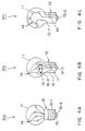
- FIG. 4A shows the type of configuration of the decorative lamp according to the first embodiment of the present invention.
- the decorative lamp 10a shown in FIG. 4A comprises a glass or hard resin hollow and transparent bulb 11; a lamp base 12 forming part of an electrode mounted to the aperture (lower part of the bulb in FIG. 4A) of the hollow and transparent bulb 11; and a plurality of (4 in FIG. 4A) LED lamps 14 enclosed by the bulb 11.
- the plurality of LED lamps 14 are individually connected between one electrode 12-1 (side of the metal base 12) and the other electrode 12-2 (conductor unit attached to the reverse side of the lamp base 12 through an insulating material 15) via a lead described later through respective resistors 17, 18, etc.
- the resister 17 or 18 can be a capacitor or a small circuit substrate of the size of, for example, a 10-cent coin provided with a resister, etc.
- FIG. 4B shows the type of configuration of the decorative lamp according to the second embodiment of the present invention.
- the decorative lamp 10b (shown as cut open at left-front in FIG. 4B) comprises the bulb 11, the metal base 12, and a plurality of (6 in FIG. 4B) LED lamps 14.
- the decorative lamp 10b is designed to have 6 LED lamps 14 connected in parallel to two ring-shaped terminals 16-1 and 16-2.
- One ring-shaped terminal 16-1 is connected to one electrode 12-1 of the lamp base 12 while the other terminal 16-2 is connected to the other electrode 12-2 of the lamp base 12 through a resistance 17.
- FIG. 4C shows the type of configuration of the decorative lamp according to the third embodiment of the present invention.
- the decorative lamp 10c (shown as cut open at left-front in FIG. 4C) comprises the bulb 11, the lamp base 12, and a plurality of (5 in FIG. 4C) LED lamps 14.
- a plurality of LED lamps 14 are connected in series, and the lamp at one end is connected to one electrode 12-1 of the lamp base 12 while the lamp at the other end is connected to the other electrode 12-2 of the lamp base 12 through a resistance.
- the number of the LED lamps 14 enclosed in the bulb 11 can be optional.
- the LED lamps 14 can be connected to the lamp base 12 individually, in parallel, or in series. In any case, the LED lamps 14 are connected to the electrode through a resistor, a capacitor, or a small circuit substrate having an appropriate value depending on the connection method and a total number of the LED lamps 14, and an applicable voltage of power source.
- FIGs. 5A through 5F show examples of various configurations of the LED lamps 14 used for the above described decorative lamp 10a, 10b, or 10c.
- FIGs. 5A, 5B, 5E, and 5F are side sectional views
- FIGs. 5C and 5D are side views.
- 5A through 5F comprises a dome-shaped portion 21 (21a, 21b, 21c, 21d, 21e, and 21f) made of glass or resin such as epoxy resin; two leads 22 one of which is extended outside the dome-shaped portion 21 and the other of which is embedded into the dome-shaped portion 21; and an LED chip 23 connected to the other end of the two leads 22 and embedded into the dome-shaped portion 21 (the LED chip 23 cannot be seen in FIGs. 5C and 5D because they are side views).
- the LED chip 23 is provided with one LED element emitting light of appropriate color. It is well-known that the variations of the color of the light emitted by an LED element depend on the material of the LED element. For example, the Ga-As configuration in the p-n junction gives a color of an infrared ray. The Ga-P configuration with the semiconductor doped with O 2 gives a red color. The Ga-P configuration with the semiconductor doped with N 2 gives a green color. Furthermore, the LED element emitting a blue light has recently been put for practical use from the development stage. The quantity of light of the LED lamps 14 depends on the current flowing through the bias voltage applied to the LED element. Therefore, the quantity of light can be changed by appropriately amending the resistance value of a resistance element. Otherwise, the number of LED elements for the LED chip 23 can be increased, or the number of chips embedded in a dome-shaped portion can be increased.
- the diameter of the dome-shaped portion 21 is designed to be 3 - 10mm, but can be larger or smaller than these values.
- the surface of the dome-shaped portions 21 (21a, 21b, 21c, 21d, 21e, and 21f) are processed with respective treatments.
- the LED lamp 14a shown in FIG. 5A is etched or has formed on the surface of the dome-shaped portion 21a a frosted glass surface 25.
- a part of the light emitted from the LED chip 23 is refracted at random and emitted outside, and the remaining part is reflected inside the dome-shaped portion 21a at random at the interface between the surface of the frosted-glass-surface dome-shaped portion 21a and air.
- a part of the light reflected inward is refracted at random again and emitted outside, and the remaining part is reflected inside at random.
- the light emitted from the LED lamp 14a is diffused and emitted in all directions except backward from the base of the bulb-shaped portion 21a.
- a side 26 of the dome-shaped portion 21b is smooth, but a bowl-shaped concave portion 27 is designed by cutting or forming at the top (on the front) of the LED lamp. If the slope of the surface of the bowl-shaped concave portion 27 is appropriately set, then a part of the light emitted with a small diffusion angle from the LED chip 23 is refracted outside and diffused, and the remaining portion is reflected in the horizontal direction and emitted outside from the side of the LED lamp. In this case, the light is emitted forward, sideward, and obliquely backward from the dome-shaped portion 21b, that is, in all directions except backward from the base of the dome-shaped portion 21b.
- an irregular diamond-cut surface 28 is provided by etching (or forming) over the entire surface of the dome-shaped portion 21. Also in this case, the light emitted with a small diffusion angle from the LED chip 23 is randomly reflected at the interface between the irregular diamond-cut surface 28 of the dome-shaped portion 21c and the air, and then emitted in all directions except backward from the base of the dome-shaped portion 21c.
- the LED lamp 14d shown in FIG. 5D is formed by applying a large number of small particles 29 of the same material as the body of the dome-shaped portion 21d over the dome-shaped portion 21d using a resin adhesive, etc. Also in this case, the light emitted with a small diffusion angle from the LED chip 23 is randomly reflected at the interface between the irregular surface of the small particles 29 of the dome-shaped portion 21d and the air, and then emitted in all directions except backward from the base of the dome-shaped portion 21d.
- the LED lamp 14e shown in FIG. 5E is formed by covering the dome-shaped portion 21e of a normal LED lamp with an optically diffusing cap 31.
- the optical diffusion of the cap 31 can be optionally defined. For example, it can be designed to have the surface as shown in FIG. 5A, 5C, or 5D. Since the cap 31 covers a normal LED lamp as described above, an existing LED lamp can be conveniently used. Also in this case, the light emitted with a small diffusion angle from the LED chip 23 is diffused by the light diffusion of the cap 31 covering the dome-shaped portion 21e and the air, and then emitted in all directions except backward from the base of the dome-shaped portion 21e.
- the LED lamp 14f shown in FIG. 5F is formed by including an optically-diffusing agent 32.
- the dome-shaped portion 21f appears milky.
- the light from the LED chip 23 is diffused by the optically diffusing agent and emitted in the dome-shaped portion 21f.
- the light is fluorescent and emitted in all directions except backward from the base of the dome-shaped portion 21e.
- LED lamps 14 of any shape shown in FIGs. 5A through 5F, enclosed in the decorative lamps 10 shown in FIGs. 4A through 4C emit light in all directions, they can realize a decorative lamp whose light can be seen from any directions as with conventional small filament lamps.
- the LED lamps are durable, power-saving, easy in setting the color of light, and gives a sparkling light specific to LED whose wavelength has converged, thereby forming an appropriate decorative bulb.
- FIGs. 6A through 6G show some examples of the applicable forms of decorative lamps enclosing the above described LED lamps 14.
- FIGs. 6A through 6E show examples of decorative bulbs having lamp bases which can be turned into sockets. In these figures, the LED lamps enclosed in the bulbs are omitted.
- FIG. 6A shows a ball-shaped bulb
- FIG. 6B shows a filament-lamp-type bulb
- FIG. 6C shows a little long bulb
- FIG. 6D shows a long bulb
- FIG. 6E shows an egg-shaped bulb.
- FIGs. 6F and 6G show examples of decorative lamps having lamp bases with two bosses. The metal base is attached to a socket by being inserted to the socket and a little turned therein with the two bosses reaching the reverse side of the socket. Thus, the metal base can be easily removed from the socket.
- FIG. 6F shows an inverted-triangle-shaped bulb
- FIG. 6G shows a ball-shaped bulb.
Landscapes
- Engineering & Computer Science (AREA)
- General Engineering & Computer Science (AREA)
- Physics & Mathematics (AREA)
- Microelectronics & Electronic Packaging (AREA)
- Optics & Photonics (AREA)
- Non-Portable Lighting Devices Or Systems Thereof (AREA)
- Led Device Packages (AREA)
- Devices For Indicating Variable Information By Combining Individual Elements (AREA)
Applications Claiming Priority (3)
| Application Number | Priority Date | Filing Date | Title |
|---|---|---|---|
| JP8204573A JPH1049077A (ja) | 1996-08-02 | 1996-08-02 | 装飾電球 |
| JP20457396 | 1996-08-02 | ||
| JP204573/96 | 1996-08-02 |
Publications (2)
| Publication Number | Publication Date |
|---|---|
| EP0822371A2 true EP0822371A2 (de) | 1998-02-04 |
| EP0822371A3 EP0822371A3 (de) | 1999-06-16 |
Family
ID=16492717
Family Applications (1)
| Application Number | Title | Priority Date | Filing Date |
|---|---|---|---|
| EP97202322A Withdrawn EP0822371A3 (de) | 1996-08-02 | 1997-07-30 | Dekorative Lampen |
Country Status (4)
| Country | Link |
|---|---|
| EP (1) | EP0822371A3 (de) |
| JP (1) | JPH1049077A (de) |
| CN (1) | CN1172921A (de) |
| TW (1) | TW350031B (de) |
Cited By (6)
| Publication number | Priority date | Publication date | Assignee | Title |
|---|---|---|---|---|
| EP1215735A1 (de) * | 2000-12-13 | 2002-06-19 | Chao-Chin Yeh | Verbesserte Lampenstruktur |
| GB2372136A (en) * | 2001-02-13 | 2002-08-14 | Edward Dyett | Random coloured light production |
| ES2193877A1 (es) * | 2002-04-15 | 2003-11-01 | La Barrera-Montenegro Mende De | Lampara decorativa. |
| RU2265969C1 (ru) * | 2004-03-10 | 2005-12-10 | Ногинов Александр Леонидович | Декоративный многоцветный светильник с устройством управления |
| FR2911038A1 (fr) * | 2006-12-27 | 2008-07-04 | Joseph Francois Mari Guiheneuf | -biled- -remplacable- |
| FR2944854A1 (fr) * | 2009-03-12 | 2010-10-29 | Blachere Iluminations | Lampe comportant un culot surmonte d'une ampoule a l'interieur de laquelle sont disposees des diodes lumineuses |
Families Citing this family (1)
| Publication number | Priority date | Publication date | Assignee | Title |
|---|---|---|---|---|
| JP2018133268A (ja) * | 2017-02-17 | 2018-08-23 | 株式会社ビートソニック | 装飾用led電球 |
Family Cites Families (4)
| Publication number | Priority date | Publication date | Assignee | Title |
|---|---|---|---|---|
| US3821590A (en) * | 1971-03-29 | 1974-06-28 | Northern Electric Co | Encapsulated solid state light emitting device |
| US4211955A (en) * | 1978-03-02 | 1980-07-08 | Ray Stephen W | Solid state lamp |
| JPH0416447Y2 (de) * | 1985-07-22 | 1992-04-13 | ||
| US5140220A (en) * | 1985-12-02 | 1992-08-18 | Yumi Sakai | Light diffusion type light emitting diode |
-
1996
- 1996-08-02 JP JP8204573A patent/JPH1049077A/ja active Pending
-
1997
- 1997-07-30 EP EP97202322A patent/EP0822371A3/de not_active Withdrawn
- 1997-07-30 TW TW086110899A patent/TW350031B/zh active
- 1997-08-01 CN CN97115319A patent/CN1172921A/zh active Pending
Non-Patent Citations (1)
| Title |
|---|
| None |
Cited By (7)
| Publication number | Priority date | Publication date | Assignee | Title |
|---|---|---|---|---|
| EP1215735A1 (de) * | 2000-12-13 | 2002-06-19 | Chao-Chin Yeh | Verbesserte Lampenstruktur |
| GB2372136A (en) * | 2001-02-13 | 2002-08-14 | Edward Dyett | Random coloured light production |
| GB2372136B (en) * | 2001-02-13 | 2003-03-19 | Edward Dyett | Random coloured light generation and illumination |
| ES2193877A1 (es) * | 2002-04-15 | 2003-11-01 | La Barrera-Montenegro Mende De | Lampara decorativa. |
| RU2265969C1 (ru) * | 2004-03-10 | 2005-12-10 | Ногинов Александр Леонидович | Декоративный многоцветный светильник с устройством управления |
| FR2911038A1 (fr) * | 2006-12-27 | 2008-07-04 | Joseph Francois Mari Guiheneuf | -biled- -remplacable- |
| FR2944854A1 (fr) * | 2009-03-12 | 2010-10-29 | Blachere Iluminations | Lampe comportant un culot surmonte d'une ampoule a l'interieur de laquelle sont disposees des diodes lumineuses |
Also Published As
| Publication number | Publication date |
|---|---|
| JPH1049077A (ja) | 1998-02-20 |
| EP0822371A3 (de) | 1999-06-16 |
| CN1172921A (zh) | 1998-02-11 |
| TW350031B (en) | 1999-01-11 |
Similar Documents
| Publication | Publication Date | Title |
|---|---|---|
| US9097396B2 (en) | LED based lighting system | |
| US12111021B2 (en) | LED filament and LED filament lamp | |
| JP4931819B2 (ja) | 照明装置 | |
| US6472823B2 (en) | LED tubular lighting device and control device | |
| US6709132B2 (en) | LED bulb | |
| US5931570A (en) | Light emitting diode lamp | |
| KR102514504B1 (ko) | 조명 장치 | |
| US20050052885A1 (en) | Structure of LED decoration lighting set | |
| US11519563B2 (en) | Light-emitting device | |
| CN101292113A (zh) | 灯 | |
| US20110085327A1 (en) | Decorative light display with LEDs | |
| JPH11177149A (ja) | 電 球 | |
| US9759389B2 (en) | LED based candelabra lamp | |
| JP6588570B2 (ja) | 光を混合するための多ディフューザーを含む照明器具 | |
| EP0822371A2 (de) | Dekorative Lampen | |
| CN223768731U (zh) | 包括灯丝元件的灯 | |
| JP2001067910A (ja) | 発光素子による照明灯 | |
| JP2005158773A (ja) | Led照明器 | |
| JP6112480B2 (ja) | 照明用光源および照明装置 | |
| JP2026509556A (ja) | Ledフィラメント及びledフィラメントランプ | |
| WO2019228836A1 (en) | Lighting module having a communication element | |
| JP2001064816A (ja) | 造花カラーライト |
Legal Events
| Date | Code | Title | Description |
|---|---|---|---|
| PUAI | Public reference made under article 153(3) epc to a published international application that has entered the european phase |
Free format text: ORIGINAL CODE: 0009012 |
|
| AK | Designated contracting states |
Kind code of ref document: A2 Designated state(s): DE FR GB IT SE |
|
| PUAL | Search report despatched |
Free format text: ORIGINAL CODE: 0009013 |
|
| RIC1 | Information provided on ipc code assigned before grant |
Free format text: 6F 21P 3/00 A, 6F 21K 7/00 B |
|
| AK | Designated contracting states |
Kind code of ref document: A3 Designated state(s): AT BE CH DE DK ES FI FR GB GR IE IT LI LU MC NL PT SE |
|
| 17P | Request for examination filed |
Effective date: 19990913 |
|
| AKX | Designation fees paid |
Free format text: DE FR GB IT SE |
|
| STAA | Information on the status of an ep patent application or granted ep patent |
Free format text: STATUS: THE APPLICATION HAS BEEN WITHDRAWN |
|
| 18W | Application withdrawn |
Withdrawal date: 20000714 |