EP0822384B1 - Treibladungskorn für eine geschichtete Treibladung - Google Patents
Treibladungskorn für eine geschichtete Treibladung Download PDFInfo
- Publication number
- EP0822384B1 EP0822384B1 EP97113204A EP97113204A EP0822384B1 EP 0822384 B1 EP0822384 B1 EP 0822384B1 EP 97113204 A EP97113204 A EP 97113204A EP 97113204 A EP97113204 A EP 97113204A EP 0822384 B1 EP0822384 B1 EP 0822384B1
- Authority
- EP
- European Patent Office
- Prior art keywords
- grain
- propellant
- propellant charge
- grains
- radius
- Prior art date
- Legal status (The legal status is an assumption and is not a legal conclusion. Google has not performed a legal analysis and makes no representation as to the accuracy of the status listed.)
- Expired - Lifetime
Links
- 239000003380 propellant Substances 0.000 title claims description 25
- 239000002245 particle Substances 0.000 title 1
- 125000006850 spacer group Chemical group 0.000 claims description 5
- 239000011888 foil Substances 0.000 claims 1
- 239000007789 gas Substances 0.000 description 2
- 239000000843 powder Substances 0.000 description 2
- 241000219504 Caryophyllales Species 0.000 description 1
- 238000011161 development Methods 0.000 description 1
- 230000018109 developmental process Effects 0.000 description 1
- 238000010304 firing Methods 0.000 description 1
- 230000001535 kindling effect Effects 0.000 description 1
Images

Classifications
-
- F—MECHANICAL ENGINEERING; LIGHTING; HEATING; WEAPONS; BLASTING
- F42—AMMUNITION; BLASTING
- F42B—EXPLOSIVE CHARGES, e.g. FOR BLASTING, FIREWORKS, AMMUNITION
- F42B5/00—Cartridge ammunition, e.g. separately-loaded propellant charges
- F42B5/02—Cartridges, i.e. cases with charge and missile
- F42B5/16—Cartridges, i.e. cases with charge and missile characterised by composition or physical dimensions or form of propellant charge, with or without projectile, or powder
Definitions
- the invention relates to a propellant grain for a stratified propellant according to the preamble of claim 1.
- a charge build-up is higher to increase the performance of existing barrel weapons Loading density required, see US-A 4,094,248 (basis for the preamble of claim 1).
- Geometrically through arrangements shaped single grains with a hexagonal cross-section are higher loading densities than can be achieved with bulk powder.
- the one on the outside of the hexagonal Grains and holes arranged inside the body have a very small cross-section so that the flame front gradually turns away from the kindled Front face spreads in the longitudinal direction.
- the invention has for its object a propellant for a stratified Propose propellant charge with good kindling.
- the invention solves this problem according to the characterizing features of claim 1.
- the polygonal multi-hole grain according to the invention has at its corner points special longitudinal grooves, the radius of which is considerably larger than the radius of the hole Grains.
- the longitudinal grooves With a stratified propellant charge with grains arranged side by side the longitudinal grooves each form flow channels with a circular cross section. The diameter of these channels ensures that the wall surface is lit. of the entire flow channels lying one behind the other, namely from the ignition side to the end of the grain, that is to say the end of the grain. Accordingly then a particularly good ignition and ignition of the grains is guaranteed, if the radius of the groove is 1.5 to 4 times the web width or after Claim 2 which is 10 to 20 times the hole radius.
- the end faces of the grains with spacers like knobs connected in one piece with the grain.
- a separate spacer such as a dimensionally stable, folded, combustible film is also the respective one Front ignition of the grains guaranteed.
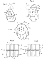
- triangular grains 2 of a propellant charge are in a propellant charge sleeve 1 10 covering the entire area with respect to the cross section of the propellant charge sleeve 1 each six-surface, (merging) surface segments 4 assembled and - corresponding to a charge length, not shown - on each other stacked.
- Each grain 2 has at its corner 3 a longitudinal groove 5 with a radius 6 and thus a corresponding circular section 7 and through holes 9.
- the radius 6 of the channels 20 is 1.5 times a web width 22 between two holes 9.
- a grain 30 is provided with a square cross section and has at its corners 31 a longitudinal groove 33 with a 90 ° cutout 32 with the Radius 6 on.
- a six-surface grain 40 has one at each of its corners 41 Longitudinal groove 43 with a 120 ° cutout 42 with radius 6 and the holes 9 on.
- the spacer 61 is a multi-edged, separate film consists of propellant powder. This film 61 ensures the Distance 52.
- the hot ignition gases include both channels 20 and subchannels 17-19 and the transverse channels 53. This is a - starting from the longitudinal grooves 5 and 32 respectively simultaneous burning of grains 2 and 30 achieved from the outside.
- Front firing fronts on the grains 2, not shown, are known in the art Way supported by the holes 9. This is the required, good ignition property on grain 2 or on the other grains 30, 40, 50, 60 before.
- the circular cross section of the channels 20 is not mandatory. This cross section can also be elliptical or different.
Landscapes
- Engineering & Computer Science (AREA)
- General Engineering & Computer Science (AREA)
- Drilling And Exploitation, And Mining Machines And Methods (AREA)
- Containers And Packaging Bodies Having A Special Means To Remove Contents (AREA)
- Optical Radar Systems And Details Thereof (AREA)
- Nozzles (AREA)
Description
- Fig. 1
- eine im Ausschnitt gezeichnete Schicht einer Treibladung in einem Treibladungsbehälter,
- Fig. 2 - 4
- polygonale Körner einer Treibladung in perspektivischer Ansicht und
- Fig. 5, 6
- zwei Lagen Treibladungskörner mit dazwischenliegenden Abstandsmitteln.
Claims (4)
- Treibladungskorn (2) für eine geschichtete Treibladung (10), bestehend aus einem polygonalen Mehrloch-Korn (2) mit außenliegenden Längsnuten (5), das in mehrfach nebeneinander liegender Anzahl eine radial dichte Packung mit in Längsrichtung verlaufenden Kanälen (20) bildet,
dadurch gekennzeichnet, daß außenliegende Längsnuten (5) nur an den Ecken (3) des Kornes (2) liegen, der Radius (6) der Längsnuten (5) das 1,5 bis 4-fache der Stegbreite (22) des Kornes (2) beträgt. - Treibladungskorn nach Anspruch 1,
dadurch gekennzeichnet, daß der Radius (6) der Längsnuten (5) das 10 bis 20-fache des Radius des Loches (9) beträgt. - Treibladungskorn nach Anspruch 1,
dadurch gekennzeichnet, daß das polygonale Korn als Dreieck (2) Viereck, (30) oder als Sechseck (40) ausgebildet ist. - Eine aus Treibladungskörnern nach Anspruch 1 bestehende Treibladung,
dadurch gekennzeichnet,daß zwischen zwei in Längsrichtung (2) aufeinandergestapelten Körnern (2, 50, 60) verbrennbare Abstandshalter (51, 61) vorgesehen sind,wobei eine formstabile, abgekantete und verbrennbare Folie zwischen den Körnern (2, 50, 60) liegt odereinstückig mit dem Korn (50) verbundene Noppen (51) vorgesehen sind.
Applications Claiming Priority (2)
| Application Number | Priority Date | Filing Date | Title |
|---|---|---|---|
| DE19631428A DE19631428A1 (de) | 1996-08-03 | 1996-08-03 | Treibladungskorn für eine geschichtete Treibladung |
| DE19631428 | 1996-08-03 |
Publications (3)
| Publication Number | Publication Date |
|---|---|
| EP0822384A2 EP0822384A2 (de) | 1998-02-04 |
| EP0822384A3 EP0822384A3 (de) | 1998-12-23 |
| EP0822384B1 true EP0822384B1 (de) | 2001-10-04 |
Family
ID=7801727
Family Applications (1)
| Application Number | Title | Priority Date | Filing Date |
|---|---|---|---|
| EP97113204A Expired - Lifetime EP0822384B1 (de) | 1996-08-03 | 1997-07-31 | Treibladungskorn für eine geschichtete Treibladung |
Country Status (2)
| Country | Link |
|---|---|
| EP (1) | EP0822384B1 (de) |
| DE (2) | DE19631428A1 (de) |
Cited By (3)
| Publication number | Priority date | Publication date | Assignee | Title |
|---|---|---|---|---|
| US11591885B2 (en) | 2018-05-31 | 2023-02-28 | DynaEnergetics Europe GmbH | Selective untethered drone string for downhole oil and gas wellbore operations |
| US12031417B2 (en) | 2018-05-31 | 2024-07-09 | DynaEnergetics Europe GmbH | Untethered drone string for downhole oil and gas wellbore operations |
| US12084962B2 (en) | 2020-03-16 | 2024-09-10 | DynaEnergetics Europe GmbH | Tandem seal adapter with integrated tracer material |
Families Citing this family (3)
| Publication number | Priority date | Publication date | Assignee | Title |
|---|---|---|---|---|
| DE10130970A1 (de) * | 2001-06-27 | 2003-01-16 | Rheinmetall W & M Gmbh | Scheibenförmig aufgebautes Treibladungsmodul |
| CA2845852A1 (en) * | 2011-09-15 | 2011-12-15 | Nitrochemie Wimmis Ag | Nitroglycerine-free multi-perforated high-performing propellant system |
| FR3006756B1 (fr) * | 2013-06-06 | 2015-07-03 | Herakles | Chargement pyrotechnique et generateur de gaz comprenant un tel chargement |
Family Cites Families (7)
| Publication number | Priority date | Publication date | Assignee | Title |
|---|---|---|---|---|
| DE95792C (de) * | ||||
| FR437228A (fr) * | 1911-12-06 | 1912-04-16 | Marie Louis Raoul Saladin | Poudre de guerre et de chasse, et son système de fabrication |
| FR463900A (fr) * | 1913-10-22 | 1914-03-06 | James Lawrence Walsh | Perfectionnements aux grains de poudre |
| FR1068300A (fr) * | 1952-12-12 | 1954-06-23 | Poudres tubulaires à cavités nervurées | |
| US2918005A (en) * | 1956-10-31 | 1959-12-22 | Schecter George | Sheet propellant |
| US4094248A (en) * | 1977-04-21 | 1978-06-13 | The United States Of America As Represented By Secretary Of The Army | High packing density propellant grains |
| US4386569A (en) * | 1979-05-30 | 1983-06-07 | The United States Of America As Represented By The Secretary Of The Army | Solid propellant grain for improved ballistic performance guns |
-
1996
- 1996-08-03 DE DE19631428A patent/DE19631428A1/de not_active Withdrawn
-
1997
- 1997-07-31 DE DE59704763T patent/DE59704763D1/de not_active Expired - Fee Related
- 1997-07-31 EP EP97113204A patent/EP0822384B1/de not_active Expired - Lifetime
Cited By (3)
| Publication number | Priority date | Publication date | Assignee | Title |
|---|---|---|---|---|
| US11591885B2 (en) | 2018-05-31 | 2023-02-28 | DynaEnergetics Europe GmbH | Selective untethered drone string for downhole oil and gas wellbore operations |
| US12031417B2 (en) | 2018-05-31 | 2024-07-09 | DynaEnergetics Europe GmbH | Untethered drone string for downhole oil and gas wellbore operations |
| US12084962B2 (en) | 2020-03-16 | 2024-09-10 | DynaEnergetics Europe GmbH | Tandem seal adapter with integrated tracer material |
Also Published As
| Publication number | Publication date |
|---|---|
| DE19631428A1 (de) | 1998-02-05 |
| EP0822384A2 (de) | 1998-02-04 |
| DE59704763D1 (de) | 2001-11-08 |
| EP0822384A3 (de) | 1998-12-23 |
Similar Documents
| Publication | Publication Date | Title |
|---|---|---|
| DE3536315C2 (de) | ||
| DE2640458C3 (de) | Druckreduzierventil | |
| DE3039404C2 (de) | Munition zum Auswerfen elektromagnetischer Düppel | |
| DE4024942A1 (de) | Monolithischer metallischer wabenkoerper mit variierender kanalzahl | |
| DE2214802A1 (de) | Feststoffraketenmotor | |
| DE3871653T2 (de) | Verfahren zum herstellen von treibladungen und mittels eines solchen verfahrens hergestellte treibladungen. | |
| DE2753721A1 (de) | Anzuendelement mit verstaerkungsladung | |
| DE19823469A1 (de) | Monolithischer metallischer Wabenkörper mit variierender Kanalzahl | |
| DE1084979B (de) | Gasturbinenbrennkammer | |
| EP0822384A2 (de) | Treibladungskorn für eine geschichtete Treibladung | |
| DE2757764C2 (de) | ||
| DE2555814C2 (de) | Flammrohrwand | |
| DE3507216A1 (de) | Verbundplatte | |
| DE3517035C1 (de) | Matrix fuer einen katalytischen Reaktor zur Abgasreinigung | |
| DE2807309C1 (de) | Sprengladung mit stachel- oder projektilbildenden Belegungen | |
| DE3416467C2 (de) | Schneidladung | |
| DE19820463A1 (de) | Tragstruktur mit einem Deformationselement mit Radialverformungsbegrenzern | |
| DE2713174A1 (de) | Waermetauscher fuer einen stirlingmotor, insbesondere fuer kraftfahrzeuge | |
| DE2433019A1 (de) | Heissgaserzeuger mit pulverladung und verfahren zur herstellung seiner pulverladung | |
| DE102004039761B4 (de) | Pulverkörper für hülsenlose Munition | |
| DE2935622C2 (de) | Vorrichtung zur Erhöhung oder Verminderung des Sauerstoffanteils der Luft sowie Verwendung dieser Vorrichtung | |
| DE1943529B1 (de) | Leinenwurfrakete | |
| EP1884737B1 (de) | Gummischrotpackung | |
| DE4142504C1 (de) | ||
| DE2606016C3 (de) | Munition und Waffensystem zur Abfeuerung dieser Munition |
Legal Events
| Date | Code | Title | Description |
|---|---|---|---|
| PUAI | Public reference made under article 153(3) epc to a published international application that has entered the european phase |
Free format text: ORIGINAL CODE: 0009012 |
|
| AK | Designated contracting states |
Kind code of ref document: A2 Designated state(s): DE FR GB SE |
|
| RAP1 | Party data changed (applicant data changed or rights of an application transferred) |
Owner name: DIEHL STIFTUNG & CO. |
|
| PUAL | Search report despatched |
Free format text: ORIGINAL CODE: 0009013 |
|
| AK | Designated contracting states |
Kind code of ref document: A3 Designated state(s): AT BE CH DE DK ES FI FR GB GR IE IT LI LU MC NL PT SE |
|
| 17P | Request for examination filed |
Effective date: 19981124 |
|
| 17Q | First examination report despatched |
Effective date: 19990325 |
|
| AKX | Designation fees paid |
Free format text: DE FR GB SE |
|
| GRAG | Despatch of communication of intention to grant |
Free format text: ORIGINAL CODE: EPIDOS AGRA |
|
| GRAG | Despatch of communication of intention to grant |
Free format text: ORIGINAL CODE: EPIDOS AGRA |
|
| GRAH | Despatch of communication of intention to grant a patent |
Free format text: ORIGINAL CODE: EPIDOS IGRA |
|
| GRAH | Despatch of communication of intention to grant a patent |
Free format text: ORIGINAL CODE: EPIDOS IGRA |
|
| GRAA | (expected) grant |
Free format text: ORIGINAL CODE: 0009210 |
|
| AK | Designated contracting states |
Kind code of ref document: B1 Designated state(s): DE FR GB SE |
|
| REF | Corresponds to: |
Ref document number: 59704763 Country of ref document: DE Date of ref document: 20011108 |
|
| REG | Reference to a national code |
Ref country code: GB Ref legal event code: IF02 |
|
| GBT | Gb: translation of ep patent filed (gb section 77(6)(a)/1977) |
Effective date: 20020104 |
|
| ET | Fr: translation filed | ||
| PLBE | No opposition filed within time limit |
Free format text: ORIGINAL CODE: 0009261 |
|
| STAA | Information on the status of an ep patent application or granted ep patent |
Free format text: STATUS: NO OPPOSITION FILED WITHIN TIME LIMIT |
|
| 26N | No opposition filed | ||
| PGFP | Annual fee paid to national office [announced via postgrant information from national office to epo] |
Ref country code: DE Payment date: 20030917 Year of fee payment: 7 |
|
| PGFP | Annual fee paid to national office [announced via postgrant information from national office to epo] |
Ref country code: GB Payment date: 20040625 Year of fee payment: 8 |
|
| PGFP | Annual fee paid to national office [announced via postgrant information from national office to epo] |
Ref country code: FR Payment date: 20040630 Year of fee payment: 8 |
|
| PGFP | Annual fee paid to national office [announced via postgrant information from national office to epo] |
Ref country code: SE Payment date: 20040726 Year of fee payment: 8 |
|
| PG25 | Lapsed in a contracting state [announced via postgrant information from national office to epo] |
Ref country code: DE Free format text: LAPSE BECAUSE OF NON-PAYMENT OF DUE FEES Effective date: 20050201 |
|
| PG25 | Lapsed in a contracting state [announced via postgrant information from national office to epo] |
Ref country code: GB Free format text: LAPSE BECAUSE OF NON-PAYMENT OF DUE FEES Effective date: 20050731 |
|
| PG25 | Lapsed in a contracting state [announced via postgrant information from national office to epo] |
Ref country code: SE Free format text: LAPSE BECAUSE OF NON-PAYMENT OF DUE FEES Effective date: 20050801 |
|
| GBPC | Gb: european patent ceased through non-payment of renewal fee |
Effective date: 20050731 |
|
| PG25 | Lapsed in a contracting state [announced via postgrant information from national office to epo] |
Ref country code: FR Free format text: LAPSE BECAUSE OF NON-PAYMENT OF DUE FEES Effective date: 20060331 |
|
| EUG | Se: european patent has lapsed | ||
| REG | Reference to a national code |
Ref country code: FR Ref legal event code: ST Effective date: 20060331 |