EP0822408A1 - Capteur tubulaire à onde évanescente pour spectroscopie d'absorption moléculaire - Google Patents
Capteur tubulaire à onde évanescente pour spectroscopie d'absorption moléculaire Download PDFInfo
- Publication number
- EP0822408A1 EP0822408A1 EP97401827A EP97401827A EP0822408A1 EP 0822408 A1 EP0822408 A1 EP 0822408A1 EP 97401827 A EP97401827 A EP 97401827A EP 97401827 A EP97401827 A EP 97401827A EP 0822408 A1 EP0822408 A1 EP 0822408A1
- Authority
- EP
- European Patent Office
- Prior art keywords
- guide
- light
- tubular
- fluid
- sensor
- Prior art date
- Legal status (The legal status is an assumption and is not a legal conclusion. Google has not performed a legal analysis and makes no representation as to the accuracy of the status listed.)
- Granted
Links
- 238000004847 absorption spectroscopy Methods 0.000 title claims description 6
- 239000000835 fiber Substances 0.000 claims description 21
- 239000013307 optical fiber Substances 0.000 claims description 19
- 239000012530 fluid Substances 0.000 claims description 12
- 238000004458 analytical method Methods 0.000 claims description 7
- 230000015572 biosynthetic process Effects 0.000 claims description 5
- 230000003993 interaction Effects 0.000 claims description 5
- 239000000463 material Substances 0.000 claims description 5
- 230000002093 peripheral effect Effects 0.000 claims description 5
- 238000007789 sealing Methods 0.000 claims description 3
- 230000003100 immobilizing effect Effects 0.000 claims description 2
- 230000003287 optical effect Effects 0.000 description 19
- 239000000243 solution Substances 0.000 description 13
- 239000007788 liquid Substances 0.000 description 9
- 239000002609 medium Substances 0.000 description 9
- 230000005855 radiation Effects 0.000 description 9
- 238000010521 absorption reaction Methods 0.000 description 5
- 238000005259 measurement Methods 0.000 description 5
- 239000006193 liquid solution Substances 0.000 description 4
- 230000035515 penetration Effects 0.000 description 4
- 238000004611 spectroscopical analysis Methods 0.000 description 4
- 238000002835 absorbance Methods 0.000 description 3
- 230000008901 benefit Effects 0.000 description 3
- 239000004020 conductor Substances 0.000 description 3
- 239000011521 glass Substances 0.000 description 3
- 241000894007 species Species 0.000 description 3
- VYPSYNLAJGMNEJ-UHFFFAOYSA-N Silicium dioxide Chemical compound O=[Si]=O VYPSYNLAJGMNEJ-UHFFFAOYSA-N 0.000 description 2
- 230000006399 behavior Effects 0.000 description 2
- 230000008033 biological extinction Effects 0.000 description 2
- 235000021183 entrée Nutrition 0.000 description 2
- 239000000523 sample Substances 0.000 description 2
- 241001639412 Verres Species 0.000 description 1
- 230000002745 absorbent Effects 0.000 description 1
- 239000002250 absorbent Substances 0.000 description 1
- XAGFODPZIPBFFR-UHFFFAOYSA-N aluminium Chemical compound [Al] XAGFODPZIPBFFR-UHFFFAOYSA-N 0.000 description 1
- 229910052782 aluminium Inorganic materials 0.000 description 1
- 239000012482 calibration solution Substances 0.000 description 1
- 230000008859 change Effects 0.000 description 1
- 239000013626 chemical specie Substances 0.000 description 1
- 238000005253 cladding Methods 0.000 description 1
- 230000006835 compression Effects 0.000 description 1
- 238000007906 compression Methods 0.000 description 1
- 230000008878 coupling Effects 0.000 description 1
- 238000010168 coupling process Methods 0.000 description 1
- 238000005859 coupling reaction Methods 0.000 description 1
- 230000001419 dependent effect Effects 0.000 description 1
- 239000012897 dilution medium Substances 0.000 description 1
- 230000004907 flux Effects 0.000 description 1
- 238000007654 immersion Methods 0.000 description 1
- 238000010249 in-situ analysis Methods 0.000 description 1
- 230000031700 light absorption Effects 0.000 description 1
- 230000000670 limiting effect Effects 0.000 description 1
- 238000012423 maintenance Methods 0.000 description 1
- 238000000034 method Methods 0.000 description 1
- 238000005457 optimization Methods 0.000 description 1
- 230000036961 partial effect Effects 0.000 description 1
- 238000005375 photometry Methods 0.000 description 1
- 230000001681 protective effect Effects 0.000 description 1
- 230000002829 reductive effect Effects 0.000 description 1
- 230000035945 sensitivity Effects 0.000 description 1
- 239000000377 silicon dioxide Substances 0.000 description 1
- 230000001052 transient effect Effects 0.000 description 1
Images

Classifications
-
- G—PHYSICS
- G01—MEASURING; TESTING
- G01N—INVESTIGATING OR ANALYSING MATERIALS BY DETERMINING THEIR CHEMICAL OR PHYSICAL PROPERTIES
- G01N21/00—Investigating or analysing materials by the use of optical means, i.e. using sub-millimetre waves, infrared, visible or ultraviolet light
- G01N21/17—Systems in which incident light is modified in accordance with the properties of the material investigated
- G01N21/55—Specular reflectivity
- G01N21/552—Attenuated total reflection
Definitions
- the present invention relates to a sensor evanescent wave tubular for spectroscopy molecular absorption.
- I 0, ⁇ be the intensity of the incident radiation and I T, ⁇ be the intensity of the radiation transmitted at the wavelength ⁇ .
- the highest measurable optical densities are between 4 and 7 (hence an attenuation of the signal varying between 10 4 and 10 7 ).
- the sample to analyze must be necessarily diluted subject to that the dilution medium does not disturb the optical properties of the species to be analyzed.
- One of these fibers allows the light from the light source in the device to the measurement point.
- the other optical fiber collects the radiation transmitted after an optical path of length L in the solution.
- the optical path is adjusted according to the opacity of the solution to be analyzed.
- the sensor therefore no longer plays its role of online sensor.
- the critical angle ⁇ c is defined by the following formula:
- the modeling of the behavior of electromagnetic waves at the change of medium shows that in the case where ⁇ is greater than or equal to ⁇ c , the light penetrates slightly in the second medium before being reflected towards the first.
- this depth dp is a few micrometers.
- This property is used in evanescent wave sensors.
- An electromagnetic wave propagates in an optical conductor by performing a multitude of reflections.
- the dimensions of the sensor will be strongly dependent on the angles of incidence of the wave.
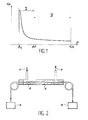
- the angle of incidence ⁇ is taken in abscissa and the intrusion depth dp is plotted in ordered.
- zone I which offers the greatest advantages (small footprint) for realization of a miniature evanescent wave sensor according to the invention, such a sensor being intended to operate in zone I.
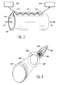
- the sensors include an optical fiber 2 without a sheath protective and placed in a branch circuit 4 where circulates the solution to be analyzed, in the direction indicated by the arrows F.
- the sensors include a glass slide 10 one side of which is immersed in the solution to be analyzed 12.
- a longitudinal slot made on the line 13 in which the solution circulates following the arrows G receives the glass slide 10 for allow this immersion.
- the opposite side of this blade is equipped of two prisms 14 and 16 at its two ends.
- these prisms 14 and 16 are respectively coupled to a light source 18 and to a light detector 20.
- the object of the present invention is to remedy the above drawbacks.
- the first end of the tubular light guide is chamfered to form a truncated cone, the apex of the corresponding cone is found inside the guide.
- the chamfer allows the spread of light in the tubular guide at angles conducive to the evanescence of the wave.
- This chamfer thus reduces the distance between the tubular light guide and the transmission-reception means.
- the second end of the tubular light guide is covered with a material capable of reflecting light.
- the sensor then has a reference internal.
- the axis X of the end of the fiber 34 located opposite the tubular guide coincides with the axis Y of the latter.
- the axes of the fibers 36 are parallel to the axis of fiber 34.
- the first end 28 of the guide tubular lumen 26 is provided with a chamfer 38 of so as to form a truncated cone, the vertex O of the cone corresponding being inside the light guide tubular 26 (on the Y axis).
- the second end 30 of the guide tubular lumen 26 is covered with a layer 40 of a material capable of reflecting light, this layer 40 thus forming a mirror at the end 30 of the guide of light 26.
- FIG. 5 We have also shown schematically in FIG. 5 a measuring device 44 which makes it possible to do molecular absorption spectroscopy and to provide the corresponding measures to users.
- the light emitted by the laser source is therefore propagates in and out of the central fiber in the form of the light beam 42 in which is located at the end 28 of the tubular guide 26.
- this beam 42 enters this guide by the chamfered end 28 thereof and propagates there with successive reflections.
- An evanescent wave forms in the liquid 24.
- the light that propagates in the guide is reflected by the mirror 40 and passes through the fibers devices 36 to then be analyzed by the device 48.
- the angle ⁇ of propagation of the light in the tubular guide 26 is chosen slightly greater than the critical angle ⁇ c to be in the zone I mentioned above.
- This angle ⁇ is adjusted by varying the distance D between the central optical fiber 34 and the large base of the truncated cone formed by the chamfer 38.
- the distance D corresponding to the guide chamfered tubular (and allowing to obtain a wave evanescent) is much less than the distance corresponding to a non-chamfered tubular guide.
- the light is guided to the reflecting end 30.
- the material that covers this end is an aluminum deposit coated with silica, which allows to totally reflect the light wave.
- the light then returns towards the end chamfered tubular guide.
- the light comes out of the tubular guide and forms a circular image centered on the Y axis of this tubular guide.
- the diameter of this image is approximately equal to twice the thickness e of the tubular guide.
- the depth of penetration of the wave light in the liquid is defined by the number of light beam reflections in the guide tubular.
- This number is a function of the thickness e of the tubular guide and of the length L of the part of this tubular guide which is in the liquid.
- the holding means 32 include a waterproof and tubular element 50 which can be seen on the figure 5.
- This element 50 comprises, on the first side, a first hole 52 provided to receive the end of the bundle of optical fibers, end which is in look of the tubular guide 26.
- This element 50 also comprises, from a second side, a second hole 54 provided to receive the chamfered end of the tubular guide 26.
- the outside diameter 2R of the tubular guide is greater than the diameter of the fiber bundle optical.
- the diameter of the second hole of the element 50 is thus greater than the diameter of the first hole of this item.
- element 50 is provided with a thread internal and the holding means 32 also include a watertight and externally threaded ring 56 which is can be screwed into the threaded part of this second hole and which is crossed by the tubular guide 26.
- An O-ring 58 is placed between this ring and an internal shoulder of the element 50, formed between the thread thereof and the second hole 54, so that this O-ring can be compressed by screwing the ring 32.
- This O-ring keeps the sealing of the interior of the element 50 when the tubular guide is immersed in the liquid and, by deformation resulting from compression, also allows immobilization of the chamfered end of the guide tubular in this element, at the distance D chosen, relative to the end of the central optical fiber 34.
- the sensor according to the invention is suitable for measuring solutions with strong optical densities.
- the senor has a Internal Reference.
- liquid solution 64 constituting a measurement standard.
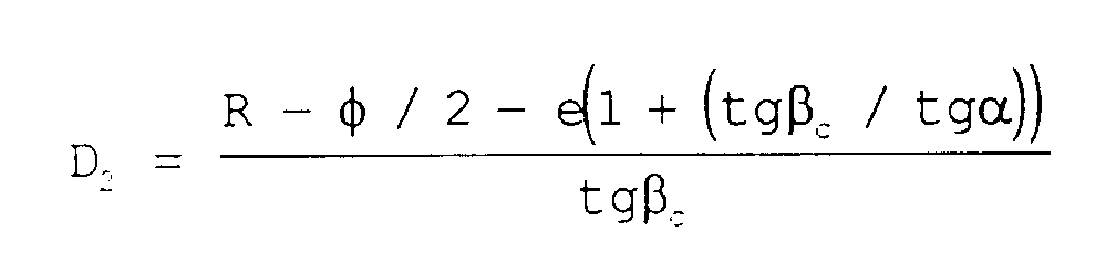
- the distance D is chosen in the interval delimited by the values D 1 and D 2 which follow, according to the sensitivity required for the measurement which one wants to make.
Landscapes
- Physics & Mathematics (AREA)
- Health & Medical Sciences (AREA)
- Life Sciences & Earth Sciences (AREA)
- Chemical & Material Sciences (AREA)
- Analytical Chemistry (AREA)
- Biochemistry (AREA)
- General Health & Medical Sciences (AREA)
- General Physics & Mathematics (AREA)
- Immunology (AREA)
- Pathology (AREA)
- Investigating Or Analysing Materials By Optical Means (AREA)
Abstract
Description
- ελ est le coefficient d'extinction molaire (exprimé en mol-1.litre.cm-1),
- L est le parcours optique dans la solution (exprimé en cm), et
- C est la concentration de l'espèce chimique à analyser (exprimée en mol.litre-1).
- Si β est inférieur à un angle critique βc, l'onde électromagnétique est totalement transmise au second milieu.
- Si β est supérieur ou égal à βc, l'onde électromagnétique est totalement réfléchie à l'interface entre les deux milieux.

- une zone I, caractérisée par une forte pénétration de l'onde, ce qui génère un important taux de réflexion par unité de longueur du conducteur optique, et
- une zone II, caractérisée par une faible pénétration de l'onde, ce qui génère un faible taux de réflexion par unité de longueur du conducteur optique.
- de la distance séparant l'entrée de la sortie de lumière,
- de leur encombrement (pour les capteurs illustrés par la figure 2),
- et des difficultés de mise en oeuvre et de remplacement (pour les capteurs illustrés par la figure 3).
- des moyens d'émission-réception destinés à émettre une lumière, qui est capable d'interagir avec le fluide, et à recevoir cette lumière après interaction de celle-ci avec ce fluide,
- un guide de lumière tubulaire qui est destiné à être plongé dans le fluide, dont une première extrémité est placée en regard des moyens d'émission-réception et dont une deuxième extrémité est apte à réfléchir la lumière qui se propage dans le guide, et
- des moyens de maintien du guide à une distance de ces moyens d'émission-réception, distance qui permet la formation de l'onde évanescente dans le fluide lorsque la lumière se propage dans le guide.
- une fibre optique centrale qui est destinée à émettre la lumière, l'extrémité de cette fibre située en regard du guide de lumière tubulaire et ce dernier étant coaxiaux, et
- des fibres optiques périphériques qui entourent la fibre optique centrale et sont destinées à recevoir la lumière sortant de la première extrémité du guide.
- un organe tubulaire qui renferme la première extrémité du guide de lumière tubulaire et l'extrémité des moyens d'émission-réception située en regard de cette première extrémité, et
- des moyens d'immobilisation de cette première extrémité à ladite distance, dans l'organe.
- des moyens de fermeture étanche des première et deuxième extrémités du guide de lumière tubulaire, et
- un fluide d'étalonnage contenu à l'intérieur de ce guide de lumière tubulaire.
- la figure 1, déjà décrite, montre les variations de la profondeur dp d'intrusion d'une onde électromagnétique dans un milieu, en fonction de l'angle d'incidence β de l'onde, à l'interface entre ce milieu et un autre milieu où se propage l'onde,
- les figures 2 et 3, déjà décrites, montrent de façon schématique des capteurs à onde évanescente connus,
- la figure 4 est une vue en perspective schématique et partielle d'un mode de réalisation particulier du capteur objet de l'invention, et
- la figure 5 est une vue en coupe longitudinale schématique du capteur représenté sur la figure 4.
- des moyens d'émission-réception 22 destinés à émettre une lumière capable d'interagir avec une solution liquide référencée 24 que l'on veut analyser par spectroscopie d'absorption moléculaire avec ce capteur, et à recevoir cette lumière après interaction de celle-ci avec le liquide,
- un guide de lumière tubulaire 26, par exemple en verre, qui est destiné à être plongé dans le liquide, dont une première extrémité 28 est placée en regard des moyens d'émission-réception 22 et dont une deuxième extrémité 30 est apte à réfléchir la lumière qui se propage dans le guide, et
- des moyens 32 de maintien du guide à une distance D de ces moyens d'émission-réception 22, cette distance permettant la formation d'une onde évanescente dans le liquide 24 lorsque la lumière se propage dans le guide 26.
- une fibre optique centrale 34 qui est destinée à émettre la lumière, et
- des fibres optiques périphériques 36 qui entourent la fibre optique centrale 34 et sont destinées à recevoir la lumière sortant de la première extrémité 28 du guide 26.
- une source-laser 46 qui produit la lumière transmise par la fibre centrale 34 et
- un dispositif de mesure 48 qui reçoit la lumière provenant des fibres optiques périphériques 36.
- entre la source 46 et la fibre centrale 34 et
- entre le dispositif 48 et les fibres périphériques 36.
- Ce capteur est susceptible d'avoir un faible encombrement, à savoir une longueur de l'ordre de 15 cm et un diamètre extérieur de l'ordre de 1 cm.
- L'entrée du rayonnement et la sortie du signal s'effectuent du même côté de ce capteur.
- Il est possible de placer ce capteur "en ligne" et il n'est donc pas nécessaire de le placer sur un flux dérivé.
- La partie creuse du guide tubulaire peut être fermée et remplie d'une solution liquide d'étalonnage.
Claims (6)
- Capteur à onde évanescente pour l'analyse d'un fluide (24) par spectroscopie d'absorption moléculaire, ce capteur étant caractérisé en ce qu'il comprend :des moyens d'émission-réception (22) destinés à émettre une lumière, qui est capable d'interagir avec le fluide, et à recevoir cette lumière après interaction de celle-ci avec ce fluide,un guide de lumière tubulaire (26) qui est destiné à être plongé dans le fluide, dont une première extrémité est placée en regard des moyens d'émission-réception, et dont une deuxième extrémité est apte à réfléchir la lumière qui se propage dans le guide, etdes moyens (32) de maintien du guide à une distance de ces moyens d'émission-réception, distance qui permet la formation de l'onde évanescente dans le fluide lorsque la lumière se propage dans le guide.
- Capteur selon la revendication 1, caractérisé en ce que les moyens d'émission-réception (22) comprennent :une fibre optique centrale (34) qui est destinée à émettre la lumière, l'extrémité de cette fibre située en regard du guide de lumière tubulaire et ce dernier étant coaxiaux, etdes fibres optiques périphériques (36) qui entourent la fibre optique centrale et sont destinées à recevoir la lumière sortant de la première extrémité du guide.
- Capteur selon l'une quelconque des revendications 1 et 2, caractérisé en ce que la première extrémité du guide de lumière tubulaire (26) est chanfreinée pour former un cône tronqué, le sommet (O) du cône correspondant étant à l'intérieur du guide.
- Capteur selon l'une quelconque des revendications 1 à 3, caractérisé en ce que la deuxième extrémité du guide de lumière tubulaire (26) est recouverte d'un matériau (40) apte à réfléchir la lumière.
- Capteur selon l'une quelconque des revendications 1 à 4, caractérisé en ce que les moyens de maintien (32) comprennent :un organe tubulaire (50) qui renferme la première extrémité du guide de lumière tubulaire et l'extrémité des moyens d'émission-réception située en regard de cette première extrémité, etdes moyens (56, 58) d'immobilisation de cette première extrémité, à ladite distance, dans l'organe.
- Capteur selon l'une quelconque des revendications 1 à 5, caractérisé en ce qu'il comprend en outre :des moyens (60, 62) de fermeture étanche des première et deuxième extrémités du guide de lumière tubulaire, etun fluide d'étalonnage (64) contenu à l'intérieur de ce guide de lumière tubulaire, le capteur ayant ainsi une référence interne.
Applications Claiming Priority (2)
| Application Number | Priority Date | Filing Date | Title |
|---|---|---|---|
| FR9609811A FR2752055B1 (fr) | 1996-08-02 | 1996-08-02 | Capteur tubulaire a onde evanescente pour spectroscopie d'absorption moleculaire |
| FR9609811 | 1996-08-02 |
Publications (2)
| Publication Number | Publication Date |
|---|---|
| EP0822408A1 true EP0822408A1 (fr) | 1998-02-04 |
| EP0822408B1 EP0822408B1 (fr) | 2005-09-21 |
Family
ID=9494788
Family Applications (1)
| Application Number | Title | Priority Date | Filing Date |
|---|---|---|---|
| EP97401827A Expired - Lifetime EP0822408B1 (fr) | 1996-08-02 | 1997-07-30 | Capteur tubulaire à onde évanescente pour spectroscopie d'absorption moléculaire |
Country Status (6)
| Country | Link |
|---|---|
| US (1) | US5889279A (fr) |
| EP (1) | EP0822408B1 (fr) |
| JP (1) | JP3895434B2 (fr) |
| AT (1) | ATE305137T1 (fr) |
| DE (1) | DE69734225T2 (fr) |
| FR (1) | FR2752055B1 (fr) |
Families Citing this family (7)
| Publication number | Priority date | Publication date | Assignee | Title |
|---|---|---|---|---|
| CN100401041C (zh) * | 2005-06-09 | 2008-07-09 | 上海交通大学 | 光波导吸收式气体传感器及测量系统 |
| US7855780B1 (en) | 2007-06-13 | 2010-12-21 | University Of South Florida | Combined fiber-optic absorption and emission measurement apparatus |
| EP2003441B1 (fr) * | 2007-06-13 | 2011-01-05 | Mettler-Toledo AG | Capteur ATR |
| CN104880415B (zh) * | 2015-06-01 | 2018-01-09 | 南京先进激光技术研究院 | 一种薄膜气体传感器 |
| WO2018075744A2 (fr) * | 2016-10-19 | 2018-04-26 | General Electric Company | Appareil et procédé de détection de guides d'ondes évanescents |
| DE102018118110B4 (de) * | 2018-07-26 | 2023-01-05 | OSRAM Opto Semiconductors Gesellschaft mit beschränkter Haftung | Sensorvorrichtung und verfahren zur herstellung einer sensorvorrichtung |
| GB2603912A (en) * | 2021-02-17 | 2022-08-24 | The Technology Partnership Plc | Optical Analysis system for Analysing Biological processes |
Citations (5)
| Publication number | Priority date | Publication date | Assignee | Title |
|---|---|---|---|---|
| US3557619A (en) * | 1969-03-17 | 1971-01-26 | Phys Chemical Research Corp | Humidity measuring method and apparatus |
| EP0128301A2 (fr) * | 1983-06-11 | 1984-12-19 | Phönix Armaturen-Werke Bregel GmbH | Réfractomètre |
| EP0194732A2 (fr) * | 1985-03-13 | 1986-09-17 | Nederlandse Organisatie voor toegepast-natuurwetenschappelijk onderzoek TNO | Capteur pour la mesure de l'indice de réfraction d'un fluide ou de la frontière de phase de deux fluides utilisant le rayonnement lumineux visible ou invisible |
| GB2217834A (en) * | 1988-04-29 | 1989-11-01 | Mine Safety Appliances Co | Evanescent sensor |
| US5170056A (en) * | 1991-02-28 | 1992-12-08 | Galileo Electro-Optics Corporation | Optical fiber coupled devices for remote spectroscopy in the infrared |
Family Cites Families (3)
| Publication number | Priority date | Publication date | Assignee | Title |
|---|---|---|---|---|
| US4844869A (en) * | 1985-09-09 | 1989-07-04 | Ord, Inc. | Immunoassay apparatus |
| US4950885A (en) * | 1989-05-08 | 1990-08-21 | I.V.P. Co. | Fluid coupled fiber optic sensor |
| US5526112A (en) * | 1993-03-05 | 1996-06-11 | Sahagen; Armen N. | Probe for monitoring a fluid medium |
-
1996
- 1996-08-02 FR FR9609811A patent/FR2752055B1/fr not_active Expired - Fee Related
-
1997
- 1997-07-24 US US08/899,649 patent/US5889279A/en not_active Expired - Lifetime
- 1997-07-30 AT AT97401827T patent/ATE305137T1/de not_active IP Right Cessation
- 1997-07-30 EP EP97401827A patent/EP0822408B1/fr not_active Expired - Lifetime
- 1997-07-30 DE DE69734225T patent/DE69734225T2/de not_active Expired - Lifetime
- 1997-08-01 JP JP20803697A patent/JP3895434B2/ja not_active Expired - Fee Related
Patent Citations (5)
| Publication number | Priority date | Publication date | Assignee | Title |
|---|---|---|---|---|
| US3557619A (en) * | 1969-03-17 | 1971-01-26 | Phys Chemical Research Corp | Humidity measuring method and apparatus |
| EP0128301A2 (fr) * | 1983-06-11 | 1984-12-19 | Phönix Armaturen-Werke Bregel GmbH | Réfractomètre |
| EP0194732A2 (fr) * | 1985-03-13 | 1986-09-17 | Nederlandse Organisatie voor toegepast-natuurwetenschappelijk onderzoek TNO | Capteur pour la mesure de l'indice de réfraction d'un fluide ou de la frontière de phase de deux fluides utilisant le rayonnement lumineux visible ou invisible |
| GB2217834A (en) * | 1988-04-29 | 1989-11-01 | Mine Safety Appliances Co | Evanescent sensor |
| US5170056A (en) * | 1991-02-28 | 1992-12-08 | Galileo Electro-Optics Corporation | Optical fiber coupled devices for remote spectroscopy in the infrared |
Also Published As
| Publication number | Publication date |
|---|---|
| DE69734225D1 (de) | 2006-02-02 |
| FR2752055A1 (fr) | 1998-02-06 |
| JPH1082734A (ja) | 1998-03-31 |
| DE69734225T2 (de) | 2006-06-22 |
| FR2752055B1 (fr) | 1998-09-11 |
| ATE305137T1 (de) | 2005-10-15 |
| US5889279A (en) | 1999-03-30 |
| EP0822408B1 (fr) | 2005-09-21 |
| JP3895434B2 (ja) | 2007-03-22 |
Similar Documents
| Publication | Publication Date | Title |
|---|---|---|
| US6118520A (en) | Dual analysis probe | |
| US5647030A (en) | Fiber optic sensor and methods and apparatus relating thereto | |
| JP4480572B2 (ja) | 微量種の分光測定のための光ファイバ共振器における拡張されたエバネッセントフィールド露出の方法と装置 | |
| US20050117157A1 (en) | Cavity ring-down detection of surface plasmon resonance in an optical fiber resonator | |
| FR2587119A1 (fr) | Appareil optique servant a effectuer des analyses | |
| EP1463925A1 (fr) | Appareil de spectroscopie par decroissance de cavite passive a fibre optique | |
| EP0822408B1 (fr) | Capteur tubulaire à onde évanescente pour spectroscopie d'absorption moléculaire | |
| US5070243A (en) | Attenuated total reflection spectroscopy | |
| EP2038640A1 (fr) | Capteur a base de fibre optique microstructuree et a reseau de bragg | |
| EP0426571A1 (fr) | Procédé d'analyse spectroscopique ponctuelle de la lumière diffractée ou absorbée par une substance placée dans un champ proche | |
| FR2583164A1 (fr) | Procede et dispositif pour determiner la couleur et la turbidite d'un fluide | |
| WO2004042385A1 (fr) | Procede de determination du point de disparition des cristaux de produits petroliers ainsi que dispositif permettant la mise en oeuvre de ce procede | |
| FR2766922A1 (fr) | Instrument de mesure de l'indice de refraction d'un fluide | |
| EP3364171B1 (fr) | Procede de detection d'une variation locale d'indice de refraction d'un milieu dielectrique situe a la surface d'un capteur optique | |
| EP0542603A1 (fr) | Capteur à fibre optique pour la mesure d'un paramètre, procédé d'évaluation d'un tel paramètre, et application du capteur à la mesure d'un gaz | |
| EP0343037B1 (fr) | Capteur optique du type optode passive, notamment destiné à la spectrofluorimétrie et à la spectrométrie raman | |
| FR3071610A1 (fr) | Systeme d'analyse par reflectometrie a fibre optique | |
| FR2725788A1 (fr) | Refractometre a fibre optique realise en optique guidee | |
| Raichlin et al. | Infrared fiber optic evanescent wave spectroscopy and its applications for the detection of toxic materials in water, in situ and in real time | |
| EP0433240A2 (fr) | Cellule optique transductrice à haute efficacité et ses applications aux capteurs optiques | |
| Benner et al. | Utilization of Optical Fibers in Remote Inelastic Light Scattering Probes | |
| FR2737571A1 (fr) | Sonde optique pour spectroscopie par reflexion totale attenuee | |
| WO2010037817A1 (fr) | Systeme optique anti-reflexion et a large acces pour la mesure d'indicatrices de diffusion de milieux fluides | |
| Willer et al. | Evanescent-field laser sensor for in-situ monitoring of volcano gas emissions | |
| CH682517A5 (fr) | Cellule optique transductrice et capteur à spectroscopie optique comprenant une cellule optique transductrice. |
Legal Events
| Date | Code | Title | Description |
|---|---|---|---|
| PUAI | Public reference made under article 153(3) epc to a published international application that has entered the european phase |
Free format text: ORIGINAL CODE: 0009012 |
|
| AK | Designated contracting states |
Kind code of ref document: A1 Designated state(s): AT DE GB IT |
|
| 17P | Request for examination filed |
Effective date: 19980710 |
|
| AKX | Designation fees paid |
Free format text: AT DE GB IT |
|
| RBV | Designated contracting states (corrected) |
Designated state(s): AT DE GB IT |
|
| GRAP | Despatch of communication of intention to grant a patent |
Free format text: ORIGINAL CODE: EPIDOSNIGR1 |
|
| GRAS | Grant fee paid |
Free format text: ORIGINAL CODE: EPIDOSNIGR3 |
|
| GRAA | (expected) grant |
Free format text: ORIGINAL CODE: 0009210 |
|
| AK | Designated contracting states |
Kind code of ref document: B1 Designated state(s): AT DE GB IT |
|
| PG25 | Lapsed in a contracting state [announced via postgrant information from national office to epo] |
Ref country code: AT Free format text: LAPSE BECAUSE OF FAILURE TO SUBMIT A TRANSLATION OF THE DESCRIPTION OR TO PAY THE FEE WITHIN THE PRESCRIBED TIME-LIMIT Effective date: 20050921 |
|
| REG | Reference to a national code |
Ref country code: GB Ref legal event code: FG4D Free format text: NOT ENGLISH |
|
| REF | Corresponds to: |
Ref document number: 69734225 Country of ref document: DE Date of ref document: 20051027 Kind code of ref document: P |
|
| GBT | Gb: translation of ep patent filed (gb section 77(6)(a)/1977) |
Effective date: 20051221 |
|
| REF | Corresponds to: |
Ref document number: 69734225 Country of ref document: DE Date of ref document: 20060202 Kind code of ref document: P |
|
| PLBE | No opposition filed within time limit |
Free format text: ORIGINAL CODE: 0009261 |
|
| STAA | Information on the status of an ep patent application or granted ep patent |
Free format text: STATUS: NO OPPOSITION FILED WITHIN TIME LIMIT |
|
| 26N | No opposition filed |
Effective date: 20060622 |
|
| PGFP | Annual fee paid to national office [announced via postgrant information from national office to epo] |
Ref country code: GB Payment date: 20110721 Year of fee payment: 15 Ref country code: DE Payment date: 20110722 Year of fee payment: 15 |
|
| PGFP | Annual fee paid to national office [announced via postgrant information from national office to epo] |
Ref country code: IT Payment date: 20110726 Year of fee payment: 15 |
|
| GBPC | Gb: european patent ceased through non-payment of renewal fee |
Effective date: 20120730 |
|
| PG25 | Lapsed in a contracting state [announced via postgrant information from national office to epo] |
Ref country code: GB Free format text: LAPSE BECAUSE OF NON-PAYMENT OF DUE FEES Effective date: 20120730 Ref country code: DE Free format text: LAPSE BECAUSE OF NON-PAYMENT OF DUE FEES Effective date: 20130201 |
|
| REG | Reference to a national code |
Ref country code: DE Ref legal event code: R119 Ref document number: 69734225 Country of ref document: DE Effective date: 20130201 |
|
| PG25 | Lapsed in a contracting state [announced via postgrant information from national office to epo] |
Ref country code: IT Free format text: LAPSE BECAUSE OF NON-PAYMENT OF DUE FEES Effective date: 20120730 |