EP0822463B1 - Dispositif de chargement et appareil de formation d'images - Google Patents
Dispositif de chargement et appareil de formation d'images Download PDFInfo
- Publication number
- EP0822463B1 EP0822463B1 EP97113353A EP97113353A EP0822463B1 EP 0822463 B1 EP0822463 B1 EP 0822463B1 EP 97113353 A EP97113353 A EP 97113353A EP 97113353 A EP97113353 A EP 97113353A EP 0822463 B1 EP0822463 B1 EP 0822463B1
- Authority
- EP
- European Patent Office
- Prior art keywords
- charged
- component
- charging
- magnetic
- application
- Prior art date
- Legal status (The legal status is an assumption and is not a legal conclusion. Google has not performed a legal analysis and makes no representation as to the accuracy of the status listed.)
- Expired - Lifetime
Links
- 230000005291 magnetic effect Effects 0.000 claims description 106
- 239000006249 magnetic particle Substances 0.000 claims description 89
- 239000010410 layer Substances 0.000 claims description 31
- 239000002245 particle Substances 0.000 claims description 10
- 239000002344 surface layer Substances 0.000 claims description 6
- 239000011230 binding agent Substances 0.000 claims description 3
- 230000002093 peripheral effect Effects 0.000 description 25
- 238000000034 method Methods 0.000 description 24
- 230000008569 process Effects 0.000 description 21
- 239000000463 material Substances 0.000 description 18
- 238000012546 transfer Methods 0.000 description 16
- 238000002347 injection Methods 0.000 description 13
- 239000007924 injection Substances 0.000 description 13
- 238000011161 development Methods 0.000 description 9
- XAGFODPZIPBFFR-UHFFFAOYSA-N aluminium Chemical compound [Al] XAGFODPZIPBFFR-UHFFFAOYSA-N 0.000 description 4
- 229910052782 aluminium Inorganic materials 0.000 description 4
- 239000011347 resin Substances 0.000 description 4
- 229920005989 resin Polymers 0.000 description 4
- 230000007613 environmental effect Effects 0.000 description 3
- 230000006872 improvement Effects 0.000 description 3
- 230000001105 regulatory effect Effects 0.000 description 3
- 238000011144 upstream manufacturing Methods 0.000 description 3
- CBENFWSGALASAD-UHFFFAOYSA-N Ozone Chemical compound [O-][O+]=O CBENFWSGALASAD-UHFFFAOYSA-N 0.000 description 2
- 230000002776 aggregation Effects 0.000 description 2
- 238000004220 aggregation Methods 0.000 description 2
- 230000008901 benefit Effects 0.000 description 2
- 230000008859 change Effects 0.000 description 2
- 230000007547 defect Effects 0.000 description 2
- 238000007599 discharging Methods 0.000 description 2
- 230000000694 effects Effects 0.000 description 2
- 239000003302 ferromagnetic material Substances 0.000 description 2
- 239000002346 layers by function Substances 0.000 description 2
- 239000004417 polycarbonate Substances 0.000 description 2
- 229920000515 polycarbonate Polymers 0.000 description 2
- 238000012545 processing Methods 0.000 description 2
- 239000004065 semiconductor Substances 0.000 description 2
- 229910001220 stainless steel Inorganic materials 0.000 description 2
- 239000010935 stainless steel Substances 0.000 description 2
- 239000004925 Acrylic resin Substances 0.000 description 1
- 229920000178 Acrylic resin Polymers 0.000 description 1
- OKTJSMMVPCPJKN-UHFFFAOYSA-N Carbon Chemical compound [C] OKTJSMMVPCPJKN-UHFFFAOYSA-N 0.000 description 1
- 239000004677 Nylon Substances 0.000 description 1
- ATJFFYVFTNAWJD-UHFFFAOYSA-N Tin Chemical compound [Sn] ATJFFYVFTNAWJD-UHFFFAOYSA-N 0.000 description 1
- 239000000654 additive Substances 0.000 description 1
- 230000000996 additive effect Effects 0.000 description 1
- 239000000853 adhesive Substances 0.000 description 1
- 230000001070 adhesive effect Effects 0.000 description 1
- 230000002411 adverse Effects 0.000 description 1
- 230000015572 biosynthetic process Effects 0.000 description 1
- 229910052799 carbon Inorganic materials 0.000 description 1
- 238000004140 cleaning Methods 0.000 description 1
- 239000012141 concentrate Substances 0.000 description 1
- 238000011109 contamination Methods 0.000 description 1
- 239000013078 crystal Substances 0.000 description 1
- 230000001419 dependent effect Effects 0.000 description 1
- 230000008021 deposition Effects 0.000 description 1
- 238000010586 diagram Methods 0.000 description 1
- 238000006073 displacement reaction Methods 0.000 description 1
- 230000005611 electricity Effects 0.000 description 1
- 230000006870 function Effects 0.000 description 1
- 229910052736 halogen Inorganic materials 0.000 description 1
- 150000002367 halogens Chemical class 0.000 description 1
- 150000007857 hydrazones Chemical class 0.000 description 1
- 230000009191 jumping Effects 0.000 description 1
- 238000005259 measurement Methods 0.000 description 1
- 230000007246 mechanism Effects 0.000 description 1
- 238000012986 modification Methods 0.000 description 1
- 230000004048 modification Effects 0.000 description 1
- 229920001778 nylon Polymers 0.000 description 1
- 230000003287 optical effect Effects 0.000 description 1
- 239000000049 pigment Substances 0.000 description 1
- 230000000630 rising effect Effects 0.000 description 1
- 238000000926 separation method Methods 0.000 description 1
- 125000006850 spacer group Chemical group 0.000 description 1
- 238000004381 surface treatment Methods 0.000 description 1
- 230000001360 synchronised effect Effects 0.000 description 1
- 238000012360 testing method Methods 0.000 description 1
- 229910000859 α-Fe Inorganic materials 0.000 description 1
Images


Classifications
-
- G—PHYSICS
- G03—PHOTOGRAPHY; CINEMATOGRAPHY; ANALOGOUS TECHNIQUES USING WAVES OTHER THAN OPTICAL WAVES; ELECTROGRAPHY; HOLOGRAPHY
- G03G—ELECTROGRAPHY; ELECTROPHOTOGRAPHY; MAGNETOGRAPHY
- G03G15/00—Apparatus for electrographic processes using a charge pattern
- G03G15/02—Apparatus for electrographic processes using a charge pattern for laying down a uniform charge, e.g. for sensitising; Corona discharge devices
- G03G15/0208—Apparatus for electrographic processes using a charge pattern for laying down a uniform charge, e.g. for sensitising; Corona discharge devices by contact, friction or induction, e.g. liquid charging apparatus
- G03G15/0241—Apparatus for electrographic processes using a charge pattern for laying down a uniform charge, e.g. for sensitising; Corona discharge devices by contact, friction or induction, e.g. liquid charging apparatus by bringing charging powder particles into contact with the member to be charged, e.g. by means of a magnetic brush
-
- G—PHYSICS
- G03—PHOTOGRAPHY; CINEMATOGRAPHY; ANALOGOUS TECHNIQUES USING WAVES OTHER THAN OPTICAL WAVES; ELECTROGRAPHY; HOLOGRAPHY
- G03G—ELECTROGRAPHY; ELECTROPHOTOGRAPHY; MAGNETOGRAPHY
- G03G2215/00—Apparatus for electrophotographic processes
- G03G2215/02—Arrangements for laying down a uniform charge
- G03G2215/021—Arrangements for laying down a uniform charge by contact, friction or induction
- G03G2215/022—Arrangements for laying down a uniform charge by contact, friction or induction using a magnetic brush
Definitions
- the present invention relates to a charging device according to the preamble of any one of claims 1 or 10.
- the present invention also relates to an image forming apparatus comprising the changing device.
- US-A-5 426 489 discloses a charging device for an image forming apparatus comprising a charging member for being supplied with a voltage including DC component and AC component to electrically charge a rotatable member to be charged.
- the charging member includes a magnetic particle layer contactable to the member to be charged and a carrying member for carrying the magnetic particle layer. Further, synchronous moving of the rotatable member and the carrying member is effected by driving means, wherein the member to be charged starts rotating after or before start of application of the AC component and before start of application of the DC component and stops rotating after or before stop of application of the AC component
- a "corona" type charging device has generally been employed as means for charging an image bearing member such as an electrophotographically sensitive member, an electrostatically recordable dielectric member, or the like.
- a corona type charging device In order to charge an object with the use of a corona type charging device, a corona type charging device is disposed next to the object, not in contact with the object, and high voltage (for example, a DC voltage of 5 kV - 8 kV) is applied to the discharge wire (metallic wire) of the corona type charging device to generate a corona shower.
- high voltage for example, a DC voltage of 5 kV - 8 kV
- the surface of the object (image bearing member) to be charged is charged to predetermined polarity and potential as it is exposed to this corona shower.
- the charging member (contact type charging member) is constituted of an electrically conductive member having an adjusted electrical resistance value.
- this contact type charging member is placed in contact with the object to be charged, and voltage (charge bias) is applied to the charging member to charge the surface of the object (image bearing member) to predetermined polarity and potential.
- a contact type charging apparatus employing an electrically conductive roller as the charging member is desirable in terms of stability in charge.
- an object (image bearing member) to be charged is charged by the electrical discharge from a charging roller, as the charging member, to the object to be charged, and therefore, the surface potential of the object (image bearing member) to be charged varies according to the variation of the electrical resistance of the object (image bearing member) to be charged, and the variation of the electrical resistance of the charge roller, which are caused by environmental changes.
- a contact type charging system charge injection type charging system
- charge injection type charging system charge injection type charging system
- Japanese Laid-Open Patent Application No. 66150/1993 Japanese Laid-Open Patent Application No. 66150/1993, and the like.
- voltage is applied to an electrically conductive contact type charging member to inject electrical charge into traps which are present in the surface layer of a photosensitive member as an object to be charged.
- This charge injection type charging system is advantageous in that not only is it less sensitive to environmental changes, but also it does not use electrical discharge to charge an object, and therefore, it does not generate ozone which reduces the service life of an image bearing member.
- a DC bias V S +V th
- V S +V th a voltage composed of a voltage of a desirable level V S and a discharge threshold voltage V th (voltage at which an object to be charged begins to be charged when DC voltage applied to a contact type charging member is gradually increased
- a magnetic brush type charging member or a fur brush type charging member are desirable from the standpoint of reliability in terms of charge, contact, and the like.
- a magnetic brush type charging member has a magnetic brush, or electrically conductive magnetic particles magnetically held, like bristles of a brush, on a carrier which doubles as a power supply terminal.
- the magnetic brush portion of a magnetic brush type charging member is placed in contact with the object, and electrical power is supplied to the carrier. More specifically, electrically conductive magnetic particles are carried directly on a magnet or on the peripheral surface of a sleeve which contains a magnet, being thereby magnetically held like bristles or a brush, wherein an object to be charged is charged by applying voltage to the magnetic brush type charging member which is fixedly disposed or rotated, with the magnetic brush portion of the magnetic brush type charging member being placed in contact with an object to be charged.
- a fur brush type charging member has a brush portion (fur brush portion) formed of electrically conductive bristles planted on a carrier which doubles as a power supply terminal. In order to charge an object, the electrically conductive bristle portion is placed in contact with the object, and power is supplied to the carrier.
- a fur brush type charging member deteriorates more than a magnetic brush type charging member in terms of charging performance.
- the bristles of the fur brush portion are liable to be semipermanently bent, causing the charging performance to deteriorate, whereas a magnetic brush type charging member does not suffer from such a phenomenon, being able to reliably maintain the charging performance.
- a magnetic brush type charging member suffers from a different problem; the magnetic particles which form a magnetic brush are adhered to the surface of an object to be charged, or become separated from the main body of the magnetic brush.
- An object to be charged must be sufficiently charged while the peripheral surface of the object is run through a charging nip, that is, the contact between the object and the magnetic brush. Therefore, the electrical resistance of the magnetic brush is rendered low. Thus, the contact resistance between the magnetic brush and the object to be charged is likely to become larger than the electrical resistance of the magnetic brush type charging member, causing magnetic particles to adhere to the surface of the object to be charged.
- FIGS 7, (a) and (b) show the changes which occur to the potential of any given spot on the surface of an object (image bearing member) to be charged while this spot passes through a charging nip N.
- the abscissa represents the elapsed time from when any given spot on the surface of the object to be charged enters the charging nip N, and the axis of ordinate represents the potential of the spot correspondent to the elapsed time.
- the width of the charging nip N is 8 mm, and the speed at which any given spot on the surface of the object to be charged is passed through the charging nip N is 150 mm/sec. In other words, the time necessary for any given spot on the surface of the object to be charged to pass through the charging nip N is approximately 53 msec.
- FIG 7 (a) represents a case in which charge bias is continuously applied to a magnetic brush type charging member.
- the potential of the spot increases with time, and by the time the spot comes out of the charging nip N, its potential reaches the same voltage level as that of the charge bias being applied to the magnetic brush type charging member.
- FIG 7 (b) represents a case in which the application of charge bias to a magnetic brush type charging member is started the instant when any given spot on the surface of an object to be charged enters the charging nip N.
- some of the magnetic particles which form the magnetic brush portion of the magnetic brush type charging member are adhered to the object to be charged.
- FIG 7 represents the surface potential level of any given spot on the surface area of an object to be charged which is in the charging nip N at the instant when the application of charge bias to a magnetic brush type charging member begins, at the instant when the spot comes out of the charging nip N.
- the abscissa shows the charging nip portion at the instant when the application of charge bias begins.
- the preceding description pertains to the phenomenon which occurs at the start of a charging process.
- the magnetic particles, which form the magnetic brush portion of a magnetic brush type charging member adhere to the surface of an object to be charged, due to the similar mechanism, at the end of the charging process.
- the magnetic particles which become separated and adhere to the surface of an object to be charged, as described above, are carried away as the surface of the object moves, and therefore, the magnetic particles which form the magnetic brush portion are gradually lost. Consequently, the magnetic brush portion becomes too thin to maintain satisfactory contact with the object to be charged, allowing the occurrence of charge failure.
- the magnetic particles which become separated from the magnetic brush portion are sometimes picked up by the developing apparatus of an image forming apparatus, and obviously adversely affect image development since the volumetric resistivity of the magnetic particles for a charging apparatus is smaller than the volumetric resistivity of the magnetic particles for a developing apparatus.
- a magnetic brush type charging member (magnetic particle carrier) may be rotated in the same direction as an object to be charged (in a charging nip, the magnetic brush portion moves in the direction opposite to the surface of an object to be charged), and/or an AC component (alternating voltage component) may be superimposed on a DC component as the voltage (charge bias) applied to a magnetic brush type charging member.
- an AC component alternating voltage component
- the magnetic particles in the magnetic brush portion 2c of a magnetic brush type charging member 2 are liable to collect on the downstream side of the charging nip N, relative to the direction a in which an object 1 to be charged is moved (rotated).
- the primary object of the present invention is to provide a charging apparatus and an image forming apparatus, in which the magnetic particles of the charging apparatus do not adhere to an object to be charged.
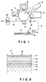
- Figure 1 is a schematic elevation of an image forming apparatus in accordance with the present invention.
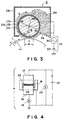
- Figure 2 is a schematic section of the surface portion of a photosensitive member in accordance with the present invention, depicting the laminar structure thereof.
- Figure 3 is an enlarged schematic side elevation of a magnetic brush type charging apparatus.
- Figure 4 is a diagram which shows a method for measuring the volumetric resistivity value of magnetic particles.
- Figure 5 is a graph which shows the relationship between the bias applied and the level of the obtained potential, when an object is charged using a charge injection system, and the relationship between the bias applied and the level of the obtained potential, when an object is charged using an electrical discharge based system.
- Figure 6 is a schematic section of a charging nip portion, depicting the behavior of magnetic particles.
- Figures 7, (a), (b) and (c) are graphs which show the relationship among the level of charge bias applied to any given spot on the surface of an object to be charged, the level of the potential obtained by the spot, the elapsed time from the beginning of the charge bias application, and the position of the spot at the beginning of charge bias application.
- FIG. 1 is a schematic side elevation of an image forming apparatus in accordance with the present invention.
- the image forming apparatus in this embodiment is a laser beam printer which employs a transfer type electrophotographic process.
- a reference numeral 1 designates an electrophotographically sensitive member as an image bearing member (object to be charged) in the form of a drum (hereinafter, "drum"). In this embodiment, it is rotatively driven in the clockwise direction indicated by an arrow mark a at a process speed (peripheral velocity) of 150 mm/sec.
- the drum 1 is an organic photoconductive member which is negatively chargeable by charge injection.
- the drum 1 comprises an aluminum drum 1a, that is, a base member, having a diameter of 30 mm, and first to fifth functional layers 1b - 1f laminated on the base member in this order from the bottom. The function of each layer will be described in Section (2).
- a reference numeral 2 designates a means for charging the drum 1.
- it is a magnetic brush type charging apparatus.
- the peripheral surface of the rotary drum 1 is substantially uniformly charged to a potential level of -700 V with the use of the magnetic brush type charging apparatus 2, which injects charge into an object by being placed in contact with the object.
- This magnetic brush type charging member 2 will be described in more detail in Section (3).
- a reference numeral 3 designates an image information exposing means.
- this laser beam scanner 3 comprises a semiconductor laser, a polygon mirror, an F- ⁇ lens, and the like.
- sequential electrical digital signals reflecting the information of a target image are inputted from an unillustrated host apparatus, for example, an original reading apparatus, a computer, or a word processor.
- the laser beam scanner 3 projects a scanning laser beam L modulated with the sequential electric digital signal onto the surface of the uniformly charged surface of the rotary drum 1, exposing thereby the surface.
- an electrostatic image correspondent to the information of the target image is formed on the peripheral surface of the rotary drum 1.
- a reference numeral 4 designates a means for developing the electrostatic latent image.
- it is a developing apparatus employing a single component, noncontact jumping development system, and uses magnetic toner as developer. It reversely develops the electrostatic latent image formed on the peripheral surface of the rotary drum 1 into a toner image.
- a reference numeral 8 designates a sheet feeder cassette. It stores recording material P (transfer material) in stacks. As a sheet feeder roller 9 is driven, the recording materials P stored in stacks in the sheet feeder cassette 8 are fed out of the cassette 8 one by one, being separated as they are fed out, and then are conveyed to a registration roller pair 12 through a sheet path 11 inclusive of a conveyer roller pair 10.
- the registration roller 12 controls the recording material P so that the recording material P is fed, with a predetermined timing, into a transfer station, that is, the nip between the rotary drum 1 and a transfer charger 5 (corona type charger).
- the transfer charger 5 charges the back (bottom) side of the recording material P to the polarity opposite to the polarity of toner as the recording material P is fed into the transfer station.
- the toner image on the peripheral surface of the rotary drum 1 is electrostatically transferred onto the front (top) surface of the recording material P, continuously from the leading end to the trailing end, as the recording material P is fed into the transfer station.
- the recording material P After receiving the toner image while passing through the transfer station, the recording material P is separated from the rotary drum 1 starting from the leading end, and is introduced into a fixing apparatus 14 (for example, a heat roller type fixing apparatus), in which the toner image is fixed to the recording material P. Thereafter, the recording material P is discharged as a finished print from the image forming apparatus.
- a fixing apparatus 14 for example, a heat roller type fixing apparatus
- the peripheral surface of the rotary drum 1 is cleaned by the cleaning blade of a cleaner 6 to remove the toner which fails to be transferred and remains on the peripheral surface of the rotary drum 1. Then, the peripheral surface of the rotary drum 1 is exposed by a pre-exposure lamp 7, being thereby removed of the remaining charge (electrical memory is removed), to be used for the following image formation.
- the drum 1 in this embodiment is an organic photoconductive member, which is chargeable to negative polarity by charge injection, and comprises a grounded aluminum drum 1a, that is, the base member 1a, having a diameter of 30 mm, and first to fifth functional layers laminated on the peripheral surface of the base member 1a in this order from the bottom, as shown in Figure 2, a schematic drawing of the laminar structure of the surface portion of the drum 1.
- First layer 1b approximately 20 ⁇ m thick electrically conductive undercoat layer provided to cover or smooth the defects or the like of the aluminum drum base 1a, and also to prevent the occurrence of the moire caused by the reflection of the exposure laser beam.
- Second layer 1c approximately 1 ⁇ m thick medium resistance (adjusted to approximately 10 6 ohm.cm) layer composed of Amiran resin and methoxymethylate nylon, which plays a role in preventing the negative charge from being canceled by the positive charge injected from the aluminum drum base la.
- Third layer 1d approximately 0.3 ⁇ m thick charge generation layer which is composed of resin material, in which diazoic pigment is dispersed, and generates a positive-negative charge pair as it is exposed to a laser beam.
- Fourth layer 1e charge transfer layer composed of polycarbonate and hydrazone dispersed in the polycarbonate; it is p-type semiconductor, and therefore, the negative charge given to the peripheral surface of a photosensitive member cannot pass through this layer, and only the positive charge generated in the charge generation layer 1d is transferred to the peripheral surface of the photosensitive member.
- Fifth layer 1f approximately 3 ⁇ m thick coated charge injection layer composed of photocurable acrylic resin, as binder, and a gram of light transmissive electrically conductive microscopic tin particles dispersed in the binder resin by 70 wt. %.
- the electrical resistance value of this charge injection layer 1f need to be within a range of 1x10 10 - 1x10 14 ohm.cm in order to ensure sufficient charge and also to prevent "image flow".
- the surface resistance is 1x10 11 ohm.cm.
- the volumetric resistivity of the charge injection layer If, it is obtained by measuring the volumetric resistivity of a charge injection layer sample in the form of a sheet, using a High Resistance Meter 4329A (Yokogawa-Hewlette-Packard) connected to Resistivity Cell 16008A, while applying 100 V.
- a High Resistance Meter 4329A Yamagawa-Hewlette-Packard
- FIG 3 is an enlarged side elevation of the magnetic brush type charging apparatus 2.
- the magnetic brush type charging apparatus in this embodiment roughly comprises a magnetic brush type charging member 2A, a housing 2B for the magnetic brush type charging member 2A and electrically conductive magnetic particles 2d (carrier), a power source 2C for applying charge bias to the magnetic brush type charging member 2A, and the like.
- the magnetic brush type charging member 2A in this embodiment is of a rotary sleeve type, and comprises a magnetic roller 2a, a nonmagnetic stainless steel sleeve 2b (which may be called a sleeve type terminal, electrically conductive sleeve, charger sleeve, or the like), and a magnetic brush 2c.
- the sleeve 2b is fitted around the magnetic roller 2a, and a magnetic brush 2c is constituted of the magnetic particles 2d held, like bristles of a brush, on the peripheral surface of the sleeve 2b by the magnetic force from the magnetic roller 2a within the sleeve 2b.
- the magnetic roller 2a is a nonrotative roller, and is firmly fixed.
- the sleeve 2b is coaxially rotated around the magnetic roller 2a by an unillustrated driving system in the clockwise direction indicated by an arrow mark b at a predetermined peripheral velocity, which is 225 mm/sec in this embodiment.
- the distance between the peripheral surfaces of the sleeve 2b and the drum 1 is maintained at approximately 500 ⁇ m with the use of spacer rings or the like.
- a reference figure 2e designates a regulator blade which is formed of nonmagnetic stainless steel and regulates the thickness of the magnetic brush layer.
- the blade 2e is disposed so that its tip holds a gap of 900 ⁇ m from the peripheral surface of the sleeve 2b.
- a certain amount of the magnetic particles 2d held in the housing 2B are held as the magnetic brush 2c on the peripheral surface of the sleeve 2b by the magnetic force from the magnetic roller 2a within the sleeve 2b.
- the magnetic brush 2c is rotated together with the sleeve 2b in the same direction.
- the thickness of the magnetic brush layer 2c is regulated by the blade 2e so that it remains uniform. Since the regulated thickness of the magnetic brush layer is larger than the gap between the peripheral surfaces of the sleeve 2b and the drum 1, the magnetic brush 2c forms a contact nip with a predetermined width, between the sleeve 2b and drum 1.
- This contact nip constitutes the charging nip N. Therefore, the rotary drum 1 is rubbed in the charging nip N by the magnetic brush 2c which follows the rotation of the sleeve 2b of the magnetic brush type charging member 2A. In the charging nip N, the direction in which the drum 1 moves and the direction in which the magnetic brush 2c moves are opposite to each other; therefore, their peripheral velocities relative to each other are increased.
- a predetermined charge bias is applied from a power source 2C.
- the drum 1 is rotatively driven; the sleeve 2b of the magnetic brush type charging member 2A is rotatively driven; and the predetermined charge bias is applied from the power source 2C, whereby the peripheral surface of the rotary drum 1 is uniformly charged to predetermined polarity and potential level through a contact type charging process, which, in this embodiment, is a charge injection type charging process.
- the magnetic roller 2a is fixedly disposed within the sleeve 2b so that its magnetic pole N1 (main pole) having a magnetic force of approximately 9000 G is displaced 10 deg. in the upstream direction, relative to the direction in which the drum rotates, from the point c at which the distance between the sleeve 2b and the drum 1 is smallest.
- the angle ( ⁇ in the drawing) of displacement of this main pole N1 in the upstream direction, relative to the direction in which the drum 1 is rotated, from the point c, at which the distance between the sleeve 2b and the drum 1 is smallest is in the range of 10 to 20 deg., preferably in a range of 0 to 15 deg. If the main pole N1 is displaced in the downstream direction by no less than 10 deg., the magnetic particles are liable to collect on the downstream side of the charging nip N since the magnetic particles are attracted to the position correspondent to the main pole N1. If the main pole N1 is displaced in the upstream direction by no less than 20 deg., the magnetic particles cannot be efficiently conveyed after they come out of the charging nip N, and as a result, they are liable to collect.
- the magnetic force which holds the magnetic particles on peripheral surface of the sleeve 2b will be weak, and therefore, the magnetic particles are liable to adhere to the drum 1.
- the charging nip N means the region in which the magnetic particles carried on the sleeve 2b are in contact with the drum 1 while the drum 1 is charged.
- the charge bias is applied to the sleeve 2b an the regulator blade 2e from the power source 2C.
- the charge bias in this embodiment is such a bias that is composed of a DC component and an AC component superimposed on the DC component. It should be noted here that the charge bias may be composed of a DC component alone; the presence of an AC component is not requisite.
- the value of the DC component level in this embodiment is -700 V which is the same as that of the surface potential level of the drum.
- the AC component is desired to be no less than 100 V and no more than 2000 V in peak-to-peak voltage Vpp, preferably no less than 300 V and no more than 1200 V. If the Vpp is below the aforementioned range, the effect of the AC component is weak in terms of improvement in charge uniformity and the speed at which potential level of an object to be charged rises. If the Vpp is above the aforementioned range, the aggregation of magnetic particles and the adhesion of magnetic toner to the drum surface are worse.
- the frequency of the AC component is desired to be in a range of 100 Hz to 5000 Hz, preferably, 500 Hz to 2000 Hz.
- the wave form of the AC component is desired to be a rectangular wave form, a triangular wave form, a sine wave form, or the like.
- the magnetic particles 2d which form the magnetic brush 2c in this embodiment material obtained by reducing sintered ferromagnetic material (ferrite) is used.
- ferrite sintered ferromagnetic material
- other materials may be used in the same manner.
- resin material and ferromagnetic material may be kneaded and then pulverized into particles.
- electrically conductive carbon particles or the like may be mixed into the thus obtained magnetic particles to adjust the electrical resistance value thereof, and also surface treatment may be given to the thus obtained magnetic particles.
- the magnetic particles of the magnetic brush 2c be able to desirably inject charge into the traps in the surface layer of the drum as the object to be charged, but also must be able to prevent the charging member and the drum from being damaged by the electric current which concentrates to the defects such as pin holes in the drum.
- the resistance value of the magnetic brush type charging member 2A is in the range of 1x10 4 - 1x10 9 ohm, preferably, 1x10 4 - 1x10 7 ohm. If it is no more than 1x10 4 ohm, pin hole leakage is liable to occur, and if it exceeds 1x10 9 ohm, charge is not likely to be desirably injected. Further, in order to keep the resistance value within the aforementioned range, the volumetric resistivity of the magnetic particles 2d is desired to be in a range of 1x10 4 - 1x10 9 ohm.cm, preferably, 1x10 4 - 1x10 7 ohm. cm.
- the value of the volumetric resistivity of the magnetic particles 2d is measured using the method illustrated in Figure 4. That is, the magnetic particles 2d are packed in a cell A, and a main electrode 16 and a top electrode 17 are disposed in contact with the packed magnetic particles 2d. Then, the current which flows through the packed magnetic particles 2d while the voltage from a constant voltage power source 21 is applied between the electrodes 16 and 17 is measured by an ammeter 19.
- a reference numeral 18 designates an electrically insulative member; 20, a voltmeter; and a reference numeral 23 designates a guide ring.
- the temperature and humidity were 23 °C and 65 %, respectively; the size S of the contact area between the packed magnetic particles 2d and the cell, 2 cm 2 ; thickness d, 1 mm; the load applied to the top electrode 17, 10 kg; and the applied voltage was 100 V.
- the average particle diameter of the magnetic particles 2d is desired to be such that the peak of the measured particle size distribution is in a range of 5 - 100 ⁇ m.
- the average particle diameter of the magnetic particles 2d is expressed in maximum chord length. As for the method for obtaining it, no less than 300 magnetic particles are randomly selected; their diameters are actually measured using a microscope; and the thus obtained values are arithmetrically averaged to give the average diameter of the magnetic particles 2d.
- the resistance value of the magnetic brush type charging member 2A in this embodiment was 1x10 6 ohm.cm.
- a voltage of -700 V was applied as the DC component of the charge bias, the surface potential level of the drum 1 reached -700 V.
- a DC power source was employed instead of the power source 2C illustrated in Figure 3.
- the total amount of the magnetic particles which are separated from the magnetic brush type charging member 2A and adhered to the peripheral surface of the drum 1 was measured while the drum 1 was charged under various conditions, that is, changing the order in which the drum rotation, the sleeve rotation, and the charge bias (DC component) application are stopped.
- the amount of the magnetic particles which were adhering to the drum surface in the nip after the drum 1 was charged was measured by slightly rotating the drum 1 after the drum 1 was charged.
- the interval between the points of time at which the drum rotation, the sleeve rotation, or the charge bias application was stopped was 100 msec. The results are shown in Table 1.
- the amount of the magnetic particles which were separated from the magnetic brush type charging member 2A and were adhered to the peripheral surface of the drum 1 was measured, changing the order in which the drum rotation, the sleeve rotation, and the charge bias (DC component) application were started at the beginning of a charging process in which the same DC component as that in the first embodiment was applied to the sleeve 2b. It should be noted here that the tests were conducted under the condition that no magnetic particle was adhering to the drum surface, on the area in the nip, at the beginning of the charging process. The results are shown in Table 2.
- the magnetic particle adhesion to the drum surface could be prevented by stopping the drum rotation first; therefore, the drum rotation was stopped first also in this embodiment. More specifically, the amount of the magnetic particle adhesion was measured while changing the order in which the AC application, the DC application, and the sleeve rotation are stopped after the drum rotation is stopped first, and the order in which the AC application and the DC application were stopped at the same time after the drum rotation was stopped first.
- the AC application is stopped first at the end of each charging process, which is the same as in the first embodiment. It is evident that the magnetic particle adhesion does not occur when the stopping order is "AC application ⁇ drum rotation ⁇ DC application ⁇ sleeve rotation".
- the magnetic particle adhesion did not occur when the drum rotation was started last. Therefore, the drum rotation was started last also in this embodiment.
- the amount of the magnetic particle adhesion was measured while changing the order in which the AC application, the DC application, and the sleeve rotation were started. As a result, the magnetic particle adhesion could not be observed in any of the starting order combinations, indicating that the magnetic particle adhesion can be prevented by starting the drum rotation last.
Landscapes
- Physics & Mathematics (AREA)
- Engineering & Computer Science (AREA)
- Plasma & Fusion (AREA)
- General Physics & Mathematics (AREA)
- Electrostatic Charge, Transfer And Separation In Electrography (AREA)
- Control Or Security For Electrophotography (AREA)
Claims (18)
- Dispositif de charge comportant :caractérisé en ce queun élément de charge (2A) destiné à être alimenté sous une tension comprenant une composante continue pour charger électriquement un élément rotatif (1) devant être chargé, ledit élément de charge comprenant une couche (2c) de particules magnétiques pouvant entrer en contact avec l'élément devant être chargé, et un élément rotatif (2b) de transport destiné à transporter ladite couche de particules magnétiques ;
le dispositif est agencé
de manière à commencer l'application de la composante continue avant le commencement de la rotation de l'élément devant être chargé ; et
de manière à commencer la rotation dudit élément devant être chargé après le commencement de la rotation dudit élément de transport. - Dispositif selon la revendication 1, dans lequel la tension contient une composante continue, et l'application de la composante continue est arrêtée après l'arrêt de la rotation de l'élément devant être chargé.
- Dispositif selon la revendication 2, dans lequel ledit élément de transport peut tourner, et la rotation dudit élément de transport est arrêtée après l'arrêt de l'application de la composante continue.
- Dispositif selon la revendication 1, dans lequel la tension contient une composante continue et une composante alternative.
- Dispositif selon la revendication 1, dans lequel la tension contient une composante continue et une composante alternative.
- Dispositif selon la revendication 2, dans lequel la tension contient en outre une composante alternative, et le temps d'arrêt de l'application de la composante continue est différent du temps d'arrêt de l'application de la composante alternative.
- Dispositif selon la revendication 3, dans lequel la tension contient en outre une composante alternative, et le temps d'arrêt de l'application de la composante continue est différent du temps d'arrêt de l'application de la composante alternative.
- Dispositif selon la revendication 1, dans lequel ledit élément de transport peut tourner, et les sens des mouvements de l'élément devant être chargé et dudit élément de transport sont différents l'un de l'autre dans une position où l'élément devant être chargé et ladite couche de particules magnétiques sont en contact.
- Dispositif selon la revendication 1, dans lequel ledit élément de transport comprend un élément rotatif non magnétique, et ledit appareil comporte en outre un rouleau à aimant non rotatif dans ledit élément de transport.
- Dispositif de charge comportant :caractérisé en ce queun élément de charge (2A) destiné à être alimenté sous une tension comprenant une composante continue pour charger électriquement un élément rotatif (1) devant être chargé, ledit élément de charge comprenant une couche (2c) de particules magnétiques pouvant entrer en contact avec l'élément devant être chargé, et un élément rotatif (2b) de transport destiné à transporter ladite couche de particules magnétiques ;
le dispositif est agencé
de manière à arrêter l'application de la composante continue après l'arrêt de la rotation de l'élément devant être chargé ; et
à arrêter la rotation dudit élément de transport après l'arrêt de l'application de la composante continue. - Dispositif selon la revendication 10, dans lequel la tension contient en outre une composante alternative, et le temps d'arrêt de l'application de la composante continue est différent du temps d'arrêt de l'application de la composante alternative.
- Dispositif selon la revendication 10, dans lequel la tension contient en outre une composante alternative, et le temps d'arrêt de l'application de la composante continue est différent du temps d'arrêt de l'application de la composante alternative.
- Dispositif selon la revendication 10, dans lequel ledit élément de transport peut tourner, et les sens des mouvements de l'élément devant être chargé et dudit élément de transport sont différents l'un de l'autre dans une position où l'élément devant être chargé et ladite couche de particules magnétiques sont en contact.
- Dispositif selon la revendication 10, dans lequel ledit élément de transport comprend un élément rotatif non magnétique, et ledit appareil comporte en outre un rouleau à aimant non rotatif dans ledit élément de transport.
- Appareil de formation d'images comportant
un élément rotatif (1) devant être chargé, comprenant une couche de surface (1f) ayant une résistivité volumique de 1 x 10¹⁰ à 1 x 10¹⁴ Ωcm, ledit élément devant être chargé pouvant porter une image, et
des moyens (2, 3, 4) de formation d'images destinés à former une image sur ledit élément devant être chargé, lesdits moyens de formation d'images comprenant un dispositif de charge (2) selon l'une quelconque des revendications 1 à 9. - Appareil de formation d'images comportant
un élément rotatif (1) devant être chargé comprenant une couche de surface (1f) ayant une résistivité volumique de 1 x 10¹⁰ à 1 x 10¹⁴ Ωcm, ledit élément devant être chargé pouvant porter une image, et
des moyens (2, 3, 4) de formation d'images destinés à former une image dans ledit élément devant être chargé, lesdits moyens de formation d'images comprenant un dispositif de charge (2) selon l'une quelconque des revendications 10 à 16. - Appareil selon la revendication 15 ou 16, dans lequel ladite couche de surface (1f) comprend un liant isolant et des particules électroconductrices dispersées dans celui-ci.
- Appareil selon l'une quelconque des revendications 15 à 17, dans lequel l'élément (1) devant être chargé comporte une couche photosensible électrophotographique à l'intérieur de ladite couche de surface.
Applications Claiming Priority (3)
| Application Number | Priority Date | Filing Date | Title |
|---|---|---|---|
| JP220342/96 | 1996-08-02 | ||
| JP22034296 | 1996-08-02 | ||
| JP22034296A JP3186596B2 (ja) | 1996-08-02 | 1996-08-02 | 帯電装置の制御方法、及び画像形成装置の制御方法 |
Publications (3)
| Publication Number | Publication Date |
|---|---|
| EP0822463A2 EP0822463A2 (fr) | 1998-02-04 |
| EP0822463A3 EP0822463A3 (fr) | 1998-04-22 |
| EP0822463B1 true EP0822463B1 (fr) | 2003-11-05 |
Family
ID=16749651
Family Applications (1)
| Application Number | Title | Priority Date | Filing Date |
|---|---|---|---|
| EP97113353A Expired - Lifetime EP0822463B1 (fr) | 1996-08-02 | 1997-08-01 | Dispositif de chargement et appareil de formation d'images |
Country Status (6)
| Country | Link |
|---|---|
| US (1) | US6125246A (fr) |
| EP (1) | EP0822463B1 (fr) |
| JP (1) | JP3186596B2 (fr) |
| KR (1) | KR100307684B1 (fr) |
| CN (1) | CN1161662C (fr) |
| DE (1) | DE69725939T2 (fr) |
Families Citing this family (4)
| Publication number | Priority date | Publication date | Assignee | Title |
|---|---|---|---|---|
| EP0984332B1 (fr) * | 1998-09-01 | 2003-12-10 | Canon Kabushiki Kaisha | Appareil de chargement emmagasinant des particules électroconductrices en forme de granules |
| JP4438031B2 (ja) * | 2000-01-06 | 2010-03-24 | キヤノン株式会社 | 画像形成装置 |
| JP4920981B2 (ja) * | 2006-01-30 | 2012-04-18 | キヤノン株式会社 | 画像形成装置 |
| US7848679B2 (en) * | 2007-12-26 | 2010-12-07 | Canon Kabushiki Kaisha | Image forming apparatus |
Family Cites Families (12)
| Publication number | Priority date | Publication date | Assignee | Title |
|---|---|---|---|---|
| JPH04319967A (ja) * | 1991-04-19 | 1992-11-10 | Minolta Camera Co Ltd | 画像形成装置の制御方法 |
| JPH0566150A (ja) * | 1991-09-09 | 1993-03-19 | Hitachi Ltd | 回転次数比分析方法および装置 |
| JPH06230655A (ja) * | 1993-02-03 | 1994-08-19 | Konica Corp | 画像形成装置 |
| JPH06250492A (ja) * | 1993-02-26 | 1994-09-09 | Konica Corp | 帯電装置 |
| JP3416820B2 (ja) * | 1993-03-25 | 2003-06-16 | コニカ株式会社 | 画像形成装置 |
| JPH0744069A (ja) * | 1993-07-27 | 1995-02-14 | Canon Inc | 画像形成装置 |
| TW287263B (fr) * | 1994-06-22 | 1996-10-01 | Canon Kk | |
| EP0709746B1 (fr) * | 1994-10-31 | 2001-01-10 | Canon Kabushiki Kaisha | Méthode et appareil de formation d'images, cassette de traitement et utilisation de materiau développateur pour ladite méthode |
| US5754927A (en) * | 1995-03-27 | 1998-05-19 | Canon Kabushiki Kaisha | Magnetic charging brush having particular magnetic fields |
| US5765076A (en) * | 1995-05-26 | 1998-06-09 | Oki Data Corporation | Method and apparatus for forming an electrostatic latent image with toner recovery |
| JP3236224B2 (ja) * | 1995-09-08 | 2001-12-10 | キヤノン株式会社 | 画像形成装置 |
| US5835821A (en) * | 1995-09-28 | 1998-11-10 | Canon Kabushiki Kaisha | Image forming apparatus |
-
1996
- 1996-08-02 JP JP22034296A patent/JP3186596B2/ja not_active Expired - Fee Related
-
1997
- 1997-07-30 US US08/902,940 patent/US6125246A/en not_active Expired - Lifetime
- 1997-08-01 CN CNB971153159A patent/CN1161662C/zh not_active Expired - Fee Related
- 1997-08-01 DE DE69725939T patent/DE69725939T2/de not_active Expired - Lifetime
- 1997-08-01 EP EP97113353A patent/EP0822463B1/fr not_active Expired - Lifetime
- 1997-08-01 KR KR1019970036836A patent/KR100307684B1/ko not_active Expired - Fee Related
Also Published As
| Publication number | Publication date |
|---|---|
| EP0822463A3 (fr) | 1998-04-22 |
| JP3186596B2 (ja) | 2001-07-11 |
| DE69725939T2 (de) | 2004-09-02 |
| KR100307684B1 (ko) | 2002-02-19 |
| CN1172974A (zh) | 1998-02-11 |
| EP0822463A2 (fr) | 1998-02-04 |
| JPH1048921A (ja) | 1998-02-20 |
| DE69725939D1 (de) | 2003-12-11 |
| CN1161662C (zh) | 2004-08-11 |
| KR19980018288A (ko) | 1998-06-05 |
| HK1008899A1 (en) | 1999-05-21 |
| US6125246A (en) | 2000-09-26 |
Similar Documents
| Publication | Publication Date | Title |
|---|---|---|
| US6591072B2 (en) | Image forming apparatus with changeable toner returning electric field application period | |
| KR100282828B1 (ko) | 화상 형성 장치 | |
| EP0800122B1 (fr) | Appareil de formation d'images | |
| US5666192A (en) | Charging member and image forming apparatus | |
| US5774769A (en) | Charging apparatus and image forming apparatus | |
| EP0901047B1 (fr) | Appareil de formation d'images | |
| US6157800A (en) | Charging device using a magnetic brush contactable to a member to be charged and image forming apparatus using same | |
| US6125246A (en) | Charging apparatus and image forming apparatus | |
| US7042591B1 (en) | Image exposure apparatus and image forming apparatus | |
| US6640072B2 (en) | Image forming apparatus including an image bearing member and a charging member featuring a controlled peripheral velocity difference therebetween during charging | |
| US7457555B2 (en) | Injection charging device promoting uniform charging of an image bearing member | |
| EP0864937B1 (fr) | Appareil de formation d'images | |
| HK1008899B (en) | Charging apparatus and image forming apparatus | |
| JP3544062B2 (ja) | 磁気ブラシ帯電装置及び画像形成装置 | |
| EP0628885B1 (fr) | Procédé et appareil électrophotographique effectuant les pas de l'exposition d'images et le developpement simultanément sur les côtés opposés d'un membre photosensible | |
| JP2004077971A (ja) | 画像形成装置 | |
| JP4323688B2 (ja) | 画像形成装置 | |
| JP2006163296A (ja) | 画像形成装置 | |
| JP2000293015A (ja) | 画像形成装置 | |
| JP2001038958A (ja) | 画像形成装置 | |
| JPH11149204A (ja) | 接触帯電装置及び画像形成装置 | |
| HK1002878A (en) | An image forming apparatus | |
| JP2001343811A (ja) | 画像形成装置 | |
| JPH086401A (ja) | 画像形成装置 | |
| JPH11194586A (ja) | 帯電装置、及びこれを備えた画像形成装置 |
Legal Events
| Date | Code | Title | Description |
|---|---|---|---|
| PUAI | Public reference made under article 153(3) epc to a published international application that has entered the european phase |
Free format text: ORIGINAL CODE: 0009012 |
|
| 17P | Request for examination filed |
Effective date: 19970801 |
|
| AK | Designated contracting states |
Kind code of ref document: A2 Designated state(s): DE FR GB IT |
|
| PUAL | Search report despatched |
Free format text: ORIGINAL CODE: 0009013 |
|
| AK | Designated contracting states |
Kind code of ref document: A3 Designated state(s): AT BE CH DE DK ES FI FR GB GR IE IT LI LU MC NL PT SE |
|
| AKX | Designation fees paid |
Free format text: DE FR GB IT |
|
| RBV | Designated contracting states (corrected) |
Designated state(s): DE FR GB IT |
|
| 17Q | First examination report despatched |
Effective date: 20010911 |
|
| GRAH | Despatch of communication of intention to grant a patent |
Free format text: ORIGINAL CODE: EPIDOS IGRA |
|
| GRAS | Grant fee paid |
Free format text: ORIGINAL CODE: EPIDOSNIGR3 |
|
| GRAA | (expected) grant |
Free format text: ORIGINAL CODE: 0009210 |
|
| AK | Designated contracting states |
Kind code of ref document: B1 Designated state(s): DE FR GB IT |
|
| REG | Reference to a national code |
Ref country code: GB Ref legal event code: FG4D |
|
| REF | Corresponds to: |
Ref document number: 69725939 Country of ref document: DE Date of ref document: 20031211 Kind code of ref document: P |
|
| ET | Fr: translation filed | ||
| PLBE | No opposition filed within time limit |
Free format text: ORIGINAL CODE: 0009261 |
|
| STAA | Information on the status of an ep patent application or granted ep patent |
Free format text: STATUS: NO OPPOSITION FILED WITHIN TIME LIMIT |
|
| 26N | No opposition filed |
Effective date: 20040806 |
|
| PGFP | Annual fee paid to national office [announced via postgrant information from national office to epo] |
Ref country code: FR Payment date: 20090821 Year of fee payment: 13 |
|
| PGFP | Annual fee paid to national office [announced via postgrant information from national office to epo] |
Ref country code: IT Payment date: 20090812 Year of fee payment: 13 |
|
| REG | Reference to a national code |
Ref country code: FR Ref legal event code: ST Effective date: 20110502 |
|
| PG25 | Lapsed in a contracting state [announced via postgrant information from national office to epo] |
Ref country code: IT Free format text: LAPSE BECAUSE OF NON-PAYMENT OF DUE FEES Effective date: 20100801 |
|
| PG25 | Lapsed in a contracting state [announced via postgrant information from national office to epo] |
Ref country code: FR Free format text: LAPSE BECAUSE OF NON-PAYMENT OF DUE FEES Effective date: 20100831 |
|
| PGFP | Annual fee paid to national office [announced via postgrant information from national office to epo] |
Ref country code: GB Payment date: 20150826 Year of fee payment: 19 Ref country code: DE Payment date: 20150831 Year of fee payment: 19 |
|
| REG | Reference to a national code |
Ref country code: DE Ref legal event code: R119 Ref document number: 69725939 Country of ref document: DE |
|
| GBPC | Gb: european patent ceased through non-payment of renewal fee |
Effective date: 20160801 |
|
| PG25 | Lapsed in a contracting state [announced via postgrant information from national office to epo] |
Ref country code: GB Free format text: LAPSE BECAUSE OF NON-PAYMENT OF DUE FEES Effective date: 20160801 Ref country code: DE Free format text: LAPSE BECAUSE OF NON-PAYMENT OF DUE FEES Effective date: 20170301 |