EP0822468A2 - Entwicklungseinheit und Tonerermittlung in einem Bilderzeugungssystem - Google Patents
Entwicklungseinheit und Tonerermittlung in einem Bilderzeugungssystem Download PDFInfo
- Publication number
- EP0822468A2 EP0822468A2 EP97305771A EP97305771A EP0822468A2 EP 0822468 A2 EP0822468 A2 EP 0822468A2 EP 97305771 A EP97305771 A EP 97305771A EP 97305771 A EP97305771 A EP 97305771A EP 0822468 A2 EP0822468 A2 EP 0822468A2
- Authority
- EP
- European Patent Office
- Prior art keywords
- developing unit
- toner
- magnet
- residual amount
- existence
- Prior art date
- Legal status (The legal status is an assumption and is not a legal conclusion. Google has not performed a legal analysis and makes no representation as to the accuracy of the status listed.)
- Withdrawn
Links
Images
Classifications
-
- G—PHYSICS
- G03—PHOTOGRAPHY; CINEMATOGRAPHY; ANALOGOUS TECHNIQUES USING WAVES OTHER THAN OPTICAL WAVES; ELECTROGRAPHY; HOLOGRAPHY
- G03G—ELECTROGRAPHY; ELECTROPHOTOGRAPHY; MAGNETOGRAPHY
- G03G15/00—Apparatus for electrographic processes using a charge pattern
- G03G15/06—Apparatus for electrographic processes using a charge pattern for developing
- G03G15/08—Apparatus for electrographic processes using a charge pattern for developing using a solid developer, e.g. powder developer
- G03G15/0806—Apparatus for electrographic processes using a charge pattern for developing using a solid developer, e.g. powder developer on a donor element, e.g. belt, roller
- G03G15/0808—Apparatus for electrographic processes using a charge pattern for developing using a solid developer, e.g. powder developer on a donor element, e.g. belt, roller characterised by the developer supplying means, e.g. structure of developer supply roller
-
- G—PHYSICS
- G03—PHOTOGRAPHY; CINEMATOGRAPHY; ANALOGOUS TECHNIQUES USING WAVES OTHER THAN OPTICAL WAVES; ELECTROGRAPHY; HOLOGRAPHY
- G03G—ELECTROGRAPHY; ELECTROPHOTOGRAPHY; MAGNETOGRAPHY
- G03G15/00—Apparatus for electrographic processes using a charge pattern
- G03G15/06—Apparatus for electrographic processes using a charge pattern for developing
- G03G15/08—Apparatus for electrographic processes using a charge pattern for developing using a solid developer, e.g. powder developer
- G03G15/0896—Arrangements or disposition of the complete developer unit or parts thereof not provided for by groups G03G15/08 - G03G15/0894
-
- G—PHYSICS
- G03—PHOTOGRAPHY; CINEMATOGRAPHY; ANALOGOUS TECHNIQUES USING WAVES OTHER THAN OPTICAL WAVES; ELECTROGRAPHY; HOLOGRAPHY
- G03G—ELECTROGRAPHY; ELECTROPHOTOGRAPHY; MAGNETOGRAPHY
- G03G15/00—Apparatus for electrographic processes using a charge pattern
- G03G15/06—Apparatus for electrographic processes using a charge pattern for developing
- G03G15/08—Apparatus for electrographic processes using a charge pattern for developing using a solid developer, e.g. powder developer
- G03G15/0822—Arrangements for preparing, mixing, supplying or dispensing developer
- G03G15/0848—Arrangements for testing or measuring developer properties or quality, e.g. charge, size, flowability
- G03G15/0856—Detection or control means for the developer level
-
- G—PHYSICS
- G03—PHOTOGRAPHY; CINEMATOGRAPHY; ANALOGOUS TECHNIQUES USING WAVES OTHER THAN OPTICAL WAVES; ELECTROGRAPHY; HOLOGRAPHY
- G03G—ELECTROGRAPHY; ELECTROPHOTOGRAPHY; MAGNETOGRAPHY
- G03G15/00—Apparatus for electrographic processes using a charge pattern
- G03G15/06—Apparatus for electrographic processes using a charge pattern for developing
- G03G15/08—Apparatus for electrographic processes using a charge pattern for developing using a solid developer, e.g. powder developer
- G03G15/0822—Arrangements for preparing, mixing, supplying or dispensing developer
- G03G15/0848—Arrangements for testing or measuring developer properties or quality, e.g. charge, size, flowability
- G03G15/0856—Detection or control means for the developer level
- G03G15/086—Detection or control means for the developer level the level being measured by electro-magnetic means
-
- G—PHYSICS
- G03—PHOTOGRAPHY; CINEMATOGRAPHY; ANALOGOUS TECHNIQUES USING WAVES OTHER THAN OPTICAL WAVES; ELECTROGRAPHY; HOLOGRAPHY
- G03G—ELECTROGRAPHY; ELECTROPHOTOGRAPHY; MAGNETOGRAPHY
- G03G15/00—Apparatus for electrographic processes using a charge pattern
- G03G15/06—Apparatus for electrographic processes using a charge pattern for developing
- G03G15/08—Apparatus for electrographic processes using a charge pattern for developing using a solid developer, e.g. powder developer
- G03G15/0822—Arrangements for preparing, mixing, supplying or dispensing developer
- G03G15/0848—Arrangements for testing or measuring developer properties or quality, e.g. charge, size, flowability
- G03G15/0856—Detection or control means for the developer level
- G03G15/0862—Detection or control means for the developer level the level being measured by optical means
-
- G—PHYSICS
- G03—PHOTOGRAPHY; CINEMATOGRAPHY; ANALOGOUS TECHNIQUES USING WAVES OTHER THAN OPTICAL WAVES; ELECTROGRAPHY; HOLOGRAPHY
- G03G—ELECTROGRAPHY; ELECTROPHOTOGRAPHY; MAGNETOGRAPHY
- G03G15/00—Apparatus for electrographic processes using a charge pattern
- G03G15/06—Apparatus for electrographic processes using a charge pattern for developing
- G03G15/08—Apparatus for electrographic processes using a charge pattern for developing using a solid developer, e.g. powder developer
- G03G15/0822—Arrangements for preparing, mixing, supplying or dispensing developer
- G03G15/0887—Arrangements for conveying and conditioning developer in the developing unit, e.g. agitating, removing impurities or humidity
- G03G15/0889—Arrangements for conveying and conditioning developer in the developing unit, e.g. agitating, removing impurities or humidity for agitation or stirring
Definitions
- the present invention relates to an apparatus and method for detecting the existence or absence of a developing unit and a residual amount of toner in an image forming system.
- image forming systems such as electrophotographic printers and facsimiles print out an image on printing paper using toner.
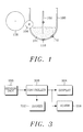
- a conventional developing unit 100 including sensors 110 and 112 for detecting the residual amount of toner 104.
- an agitator 102 is mounted in the developing unit 100.
- the agitator 102 functions to refresh the toner 104 and to transfer the toner 104 to a supplying roller 106.
- the supplying roller 106 again transfers the toner 104 to a magnetic roller 108.
- the sensors 110 and 112 for sensing the residual amount of the toner 104 are mounted on the developing unit 100, being separated from each other by a specific distance.
- the sensors 110 and 112 generate a residual amount sensing signal upon detecting the residual amount of the toner 104. However, if any one of the sensors 110 and 102 goes out of order or malfunctions for whatever reason, the residual amount of the toner 104 cannot properly be detected.
- the user may not determine the proper replacement time for the developing unit 100. Furthermore, if the developing unit 100 is not replaced with a new one at the proper time, the quality of the printed image will be undesirably degraded.
- apparatus for detecting the existence of a developing unit and a residual amount of magnetizable toner in an image forming device comprises:
- an image forming device comprises:
- the magnet is preferably mounted beneath the developing unit.
- the magnetic force exerted on the magnet causes movement of the magnet, the movement being detected by the said sensor.
- the movement may be substantially vertical.
- the device or apparatus further comprises a lever having one end on which the magnet is mounted and another end adjacent to the said sensor, the lever undergoing seesaw movement about an intermediate fulcrum according to the movement of the magnet.
- the sensor may comprise a light emitting element for generating an optical signal and a light receiving element for receiving the optical signal, the said other end of the lever being located between the light emitting and light receiving elements so that the sensor generates the said sensing signal according to the blocking and unblocking of the optical signal transferred from the light emitting element toward the light receiving element.
- control means generates a display message and/or an alarm message in accordance withe the sensing signal.
- the device or apparatus may further comprise a display for displaying the display message and/or an alarm for generating an alarm sound based on the alarm message.
- a method of detecting the existence of a developing unit and a residual amount of magnetizable toner in an image forming device comprises:
- the method may further comprise:
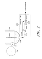
- a sensor unit 200 includes a magnet 202 which is movable up and down according to the residual amount of the magnetizable toner 104, a lever 204 for transferring the up/down movement of the magnet 202 to an optical sensor 208, a central axle 206 for securing the seesaw movement of the lever 204 and the optical sensor 208 for sensing the up/down movement of the magnet 202 in association with the lever 204 and the central axle 206 so as to generate a sensing signal.
- the lever 204 which undergoes the seesaw movement centred on the central axle 206 includes the magnet 202 mounted on one end. Further, the other end of the lever 204 closely faces the optical sensor 208.
- the magnet 202 is mounted a specific distance from the bottom outer wall of the developing unit 100 containing the magnetizable toner 104. The distance between the magnet 202 and the bottom of the developing unit 100 varies according to the residual amount of the magnetizable toner 104 contained in the developing unit 100. For example, when the residual amount of the magnetizable toner 104 contained in the developing unit 100 is relatively large, the magnet 202 moves closer to the developing unit 100.
- the magnet 202 will maintain a larger, constant distance from the developing unit 100. In this way, the magnet 202 moves up and down relative to the developing unit 100 according to the residual amount of the magnetizable toner 104 contained in the developing unit 100. The up/down movement of the magnet 202 is transferred to the optical sensor 208 by way of the lever 204 and the central axle 206.
- the optical sensor 208 includes a light emitting element 208A and a light receiving element 208B.
- the optical sensor 208 generates the sensing signal when the light receiving element 208B receives a light beam generated from the light emitting element 208A.
- One end of the lever 204 closely facing the optical sensor 208 moves up and down between the light emitting element 208A and the light receiving element 208B according to the up/down movement of the magnet 202.
- the light beam transferred from the light emitting element 208A toward the light receiving element 208B is blocked and unblocked according to the up/down movement of the lever 204.
- the optical censor 208 generates the sensing signal according to the blocking or unblocking of the light beam transferred from the light emitting element 208A toward the light receiving element 208B, based on the up/down movement of the magnet 202.
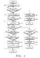
- the sensing signal generated by the optical sensor 208 according to the residual amount of the toner 104 is transferred to a controller.
- the apparatus includes the sensor unit 200, as shown in FIG. 2, for sensing the residual amount of the toner 104 to generate the sensing signal, a controller 300 for controlling the overall operation of the apparatus according to the sensing signal, a driver 302 for driving various mechanisms under the control of the controller 300, a display for displaying a display message and an alarm 306 for generating an alarm sound.
- FIG. 4 shows the process undergone by the apparatus to detect the existence or absence of the developing unit 100 and the residual amount of toner 104. Referring to FIGs. 2 to 4, the operation of the apparatus will now be described.
- the image forming system is powered on to provide each part of the system such as the controller 300 and the driver 302 with a supply voltage. Then, depending on the sensing signal generated from the sensor unit 200, the controller 300 checks whether or not the developing unit 100 is currently installed, at step 404.
- the controller 300 controls the display 304 to generate a corresponding display message, for example, "NO CARTRIDGE", at step 406.
- the controller 300 further controls the alarm 306 to generate an alarm sound.
- the controller 300 initializes the image forming system at a step 410. Then, the controller 300 checks, at step 412, whether or not a printing command signal is received. If the printing command signal is not received, the controller 300 returns to step 410 to maintain the image forming system at an initial driving status. Meanwhile, if the printing command signal is received, the controller 300 controls the driver 302 to perform a printing operation, at step 414.
- the controller 300 checks, at a step 416, whether or not the cover of the image forming system is opened during the printing operation. For example, if the cover is opened by the user because of a paper jam during the printing operation, the controller 300 checks, at step 418, whether or not the developing unit 100 is currently installed, depending upon the sensing signal generated from the sensor unit 200. If the developing unit 100 is currently installed, the process flow is ended immediately. However, if the developing unit 100 is not currently installed, the controller 300 controls the display 304 to display the corresponding display message, for example, "NO CARTRIDGE", at step 420. Furthermore, the controller 300 controls the alarm 306 to generate the alarm sound, at step 422.
- the controller 300 checks whether or not the printing operation has been completed, at step 424. If the printing operation is not completed, the controller 300 executes step 414 and the succeeding steps. Meanwhile, if the printing operation is completed, the controller 300 checks, at step 426, whether or not the residual amount of the toner 104 is smaller (or lower) than a predetermined amount, based upon the sensing signal generated from the sensor unit 200. If the residual amount of the toner 104 is not smaller than the predetermined amount, the controller 300 completes the process flow immediately.
- the controller 300 controls the display 304 to display a corresponding status message, for example, "TONER EMPTY", at step 428. Then, the controller 300 controls the alarm 306 to generate the alarm sound, at step 430.
- an apparatus includes a magnet mounted adjacent to a developing unit with a specific distance between them, so as to generate a sensing signal by detecting magnetic forces on the magnet. Then, the apparatus generates status messages concerning the existence or absence of the developing unit and the residual amount of toner, in response to the sensing signal. Accordingly, from the status messages, the user may easily check the existence of the developing unit and the residual amount of toner.
Landscapes
- Physics & Mathematics (AREA)
- General Physics & Mathematics (AREA)
- Dry Development In Electrophotography (AREA)
- Control Or Security For Electrophotography (AREA)
Applications Claiming Priority (2)
| Application Number | Priority Date | Filing Date | Title |
|---|---|---|---|
| KR9632021 | 1996-07-31 | ||
| KR1019960032021A KR980010598A (ko) | 1996-07-31 | 1996-07-31 | 화상형성시스템에서 현상기의 유무 및 현상제의 잔량을 검출하는 장치 및 방법 |
Publications (2)
| Publication Number | Publication Date |
|---|---|
| EP0822468A2 true EP0822468A2 (de) | 1998-02-04 |
| EP0822468A3 EP0822468A3 (de) | 1999-03-17 |
Family
ID=19468460
Family Applications (1)
| Application Number | Title | Priority Date | Filing Date |
|---|---|---|---|
| EP97305771A Withdrawn EP0822468A3 (de) | 1996-07-31 | 1997-07-31 | Entwicklungseinheit und Tonerermittlung in einem Bilderzeugungssystem |
Country Status (4)
| Country | Link |
|---|---|
| US (1) | US5784665A (de) |
| EP (1) | EP0822468A3 (de) |
| KR (1) | KR980010598A (de) |
| CN (1) | CN1140848C (de) |
Families Citing this family (13)
| Publication number | Priority date | Publication date | Assignee | Title |
|---|---|---|---|---|
| US5893007A (en) * | 1996-12-24 | 1999-04-06 | Samsung Electronics Co., Ltd. | Combination development unit and toner level detection service |
| JPH10333415A (ja) * | 1997-04-04 | 1998-12-18 | Canon Inc | 電子写真画像形成装置、現像ユニット、及び、プロセスカートリッジ |
| JP3632527B2 (ja) * | 1999-10-12 | 2005-03-23 | 富士ゼロックス株式会社 | 画像形成装置 |
| US6763198B2 (en) * | 2000-05-15 | 2004-07-13 | Canon Kabushiki Kaisha | Method for determining the status of attachment or detachment of developer container, and image forming apparatus |
| US7103344B2 (en) * | 2000-06-08 | 2006-09-05 | Menard Raymond J | Device with passive receiver |
| KR100581521B1 (ko) * | 2003-10-31 | 2006-05-22 | 삼성전자주식회사 | 화상형성장치 |
| JP2005195843A (ja) * | 2004-01-07 | 2005-07-21 | Seiko Epson Corp | カラー印刷モードとモノクロ印刷モードを切り替え可能にした画像形成装置 |
| JP2005274939A (ja) * | 2004-03-24 | 2005-10-06 | Kyocera Mita Corp | 画像形成装置および画像形成装置の記録剤不足警告プログラム |
| US7231153B2 (en) * | 2005-01-13 | 2007-06-12 | Xerox Corporation | Systems and methods for monitoring replaceable units |
| JP6424969B2 (ja) * | 2015-12-11 | 2018-11-21 | 株式会社村田製作所 | トナーボトル |
| JP6984214B2 (ja) * | 2017-08-01 | 2021-12-17 | 株式会社リコー | 現像剤残量検出選択システム、画像形成装置、及び現像剤残量検出選択方法 |
| JP7009132B2 (ja) | 2017-09-21 | 2022-01-25 | キヤノン株式会社 | 現像剤補給容器及び現像剤補給システム |
| KR102264525B1 (ko) * | 2018-04-19 | 2021-06-14 | 휴렛-팩커드 디벨롭먼트 컴퍼니, 엘.피. | 현상제 카트리지의 현상제 잔량을 검지하는 구조 |
Family Cites Families (15)
| Publication number | Priority date | Publication date | Assignee | Title |
|---|---|---|---|---|
| US3951309A (en) * | 1973-07-11 | 1976-04-20 | Canon Kabushiki Kaisha | Device for detecting the quantity of remaining developer |
| JPS55143410A (en) * | 1979-04-25 | 1980-11-08 | Iwatsu Electric Co Ltd | Toner detector |
| JP2812335B2 (ja) * | 1988-08-31 | 1998-10-22 | 京セラ株式会社 | トナー濃度制御方法 |
| US4998141A (en) * | 1990-08-31 | 1991-03-05 | Eastman Kodak Company | Electret toner concentration monitor |
| JPH04188172A (ja) * | 1990-11-22 | 1992-07-06 | Murata Mach Ltd | 画像形成装置 |
| JPH0667532A (ja) * | 1991-01-28 | 1994-03-11 | Fuji Xerox Co Ltd | トナーディスペンサー |
| JP2940255B2 (ja) * | 1991-09-26 | 1999-08-25 | 村田機械株式会社 | 画像形成装置におけるトナー量検出装置 |
| JPH05119567A (ja) * | 1991-10-29 | 1993-05-18 | Toshiba Corp | 画像形成装置 |
| JPH05273858A (ja) * | 1992-03-25 | 1993-10-22 | Matsushita Electric Ind Co Ltd | 粒状磁性体の空検出装置 |
| US5532790A (en) * | 1992-11-13 | 1996-07-02 | Minolta Camera Kabushiki Kaisha | Device for optically detecting an amount of remaining developer in an image forming apparatus |
| JPH06161248A (ja) * | 1992-11-18 | 1994-06-07 | Matsushita Electric Ind Co Ltd | 画像形成装置 |
| US5428427A (en) * | 1992-12-14 | 1995-06-27 | Samsung Electronics Co., Ltd. | Device for detecting toner used in an electrophotography machine |
| JP2966266B2 (ja) * | 1993-11-25 | 1999-10-25 | キヤノン株式会社 | 現像剤有無検知装置 |
| US5621221A (en) * | 1993-12-22 | 1997-04-15 | Ricoh Company, Ltd. | Toner end detection device and method |
| JPH08194367A (ja) * | 1995-01-20 | 1996-07-30 | Nec Corp | トナー容器検出装置およびこれを利用した印刷装置 |
-
1996
- 1996-07-31 KR KR1019960032021A patent/KR980010598A/ko not_active Withdrawn
-
1997
- 1997-07-31 EP EP97305771A patent/EP0822468A3/de not_active Withdrawn
- 1997-07-31 CN CNB971161488A patent/CN1140848C/zh not_active Expired - Fee Related
- 1997-07-31 US US08/903,835 patent/US5784665A/en not_active Expired - Lifetime
Also Published As
| Publication number | Publication date |
|---|---|
| US5784665A (en) | 1998-07-21 |
| CN1177753A (zh) | 1998-04-01 |
| KR980010598A (ko) | 1998-04-30 |
| CN1140848C (zh) | 2004-03-03 |
| EP0822468A3 (de) | 1999-03-17 |
Similar Documents
| Publication | Publication Date | Title |
|---|---|---|
| EP0822468A2 (de) | Entwicklungseinheit und Tonerermittlung in einem Bilderzeugungssystem | |
| US5053814A (en) | Image forming apparatus | |
| EP0743567A2 (de) | Ersatzteil mit integriertem Speicher für Gebrauchs- und Eichungsdaten | |
| US5038173A (en) | Replaceable unit determination mechanism | |
| US5455659A (en) | Apparatus with detector for detecting object to be detected | |
| US5124759A (en) | Control method for detecting a paper jam using a toner density sensor | |
| KR0150146B1 (ko) | 전자사진 현상방식 프린터의 전사전압 자동조절 제어방법 | |
| EP0393627A3 (de) | Elektrofotografische Druckvorrichtung | |
| US5745822A (en) | Image forming apparatus incorporating mechanism for automatically unsealing toner cartridge | |
| US7052007B2 (en) | Method and apparatus for controlling paper pickup in image forming system | |
| JP3177052B2 (ja) | 画像形成装置 | |
| US10401752B2 (en) | Image forming apparatus | |
| JPH08259040A (ja) | シート媒体送り装置 | |
| JP2000356895A (ja) | 現像装置 | |
| US6397020B1 (en) | Image printing apparatus and a control method thereof | |
| US7162190B2 (en) | Toner feeder | |
| JPH041682A (ja) | 印刷装置 | |
| US5105218A (en) | Method of resetting toner shortage of an image forming apparatus | |
| US7113715B2 (en) | Method and apparatus to prevent a transfer roller from being contaminated in image forming systems | |
| US7035570B2 (en) | Method and apparatus for preventing transfer roller from being contaminated in image forming system | |
| JP2931684B2 (ja) | 画像形成装置 | |
| KR100542356B1 (ko) | 화상 형성 장치의 설정 용지 제어 방법 및 그 장치 | |
| US5444830A (en) | Method and apparatus for controlling exposure and transference in an electrophotographic recording apparatus | |
| US5576819A (en) | Transfer element detect device | |
| KR0149758B1 (ko) | 레이져 빔 프린터의 자동용지 급지장치 |
Legal Events
| Date | Code | Title | Description |
|---|---|---|---|
| PUAI | Public reference made under article 153(3) epc to a published international application that has entered the european phase |
Free format text: ORIGINAL CODE: 0009012 |
|
| 17P | Request for examination filed |
Effective date: 19970814 |
|
| AK | Designated contracting states |
Kind code of ref document: A2 Designated state(s): DE FR GB |
|
| PUAL | Search report despatched |
Free format text: ORIGINAL CODE: 0009013 |
|
| AK | Designated contracting states |
Kind code of ref document: A3 Designated state(s): AT BE CH DE DK ES FI FR GB GR IE IT LI LU MC NL PT SE |
|
| AKX | Designation fees paid |
Free format text: DE FR GB |
|
| 17Q | First examination report despatched |
Effective date: 20020517 |
|
| STAA | Information on the status of an ep patent application or granted ep patent |
Free format text: STATUS: THE APPLICATION IS DEEMED TO BE WITHDRAWN |
|
| 18D | Application deemed to be withdrawn |
Effective date: 20031029 |