EP0822562A2 - Procédé et dispositif pour enrouler longitudinalement au moins un film sur un produit de câble - Google Patents
Procédé et dispositif pour enrouler longitudinalement au moins un film sur un produit de câble Download PDFInfo
- Publication number
- EP0822562A2 EP0822562A2 EP97112169A EP97112169A EP0822562A2 EP 0822562 A2 EP0822562 A2 EP 0822562A2 EP 97112169 A EP97112169 A EP 97112169A EP 97112169 A EP97112169 A EP 97112169A EP 0822562 A2 EP0822562 A2 EP 0822562A2
- Authority
- EP
- European Patent Office
- Prior art keywords
- film
- longitudinal
- cable
- tube
- cable product
- Prior art date
- Legal status (The legal status is an assumption and is not a legal conclusion. Google has not performed a legal analysis and makes no representation as to the accuracy of the status listed.)
- Granted
Links
Images

Classifications
-
- H—ELECTRICITY
- H01—ELECTRIC ELEMENTS
- H01B—CABLES; CONDUCTORS; INSULATORS; SELECTION OF MATERIALS FOR THEIR CONDUCTIVE, INSULATING OR DIELECTRIC PROPERTIES
- H01B13/00—Apparatus or processes specially adapted for manufacturing conductors or cables
- H01B13/22—Sheathing; Armouring; Screening; Applying other protective layers
- H01B13/26—Sheathing; Armouring; Screening; Applying other protective layers by winding, braiding or longitudinal lapping
- H01B13/2613—Sheathing; Armouring; Screening; Applying other protective layers by winding, braiding or longitudinal lapping by longitudinal lapping
- H01B13/268—Sheathing; Armouring; Screening; Applying other protective layers by winding, braiding or longitudinal lapping by longitudinal lapping of a non-metallic sheet
-
- G—PHYSICS
- G02—OPTICS
- G02B—OPTICAL ELEMENTS, SYSTEMS OR APPARATUS
- G02B6/00—Light guides; Structural details of arrangements comprising light guides and other optical elements, e.g. couplings
- G02B6/44—Mechanical structures for providing tensile strength and external protection for fibres, e.g. optical transmission cables
- G02B6/4479—Manufacturing methods of optical cables
-
- G—PHYSICS
- G02—OPTICS
- G02B—OPTICAL ELEMENTS, SYSTEMS OR APPARATUS
- G02B6/00—Light guides; Structural details of arrangements comprising light guides and other optical elements, e.g. couplings
- G02B6/46—Processes or apparatus adapted for installing or repairing optical fibres or optical cables
- G02B6/56—Processes for repairing optical cables
- G02B6/562—Processes for repairing optical cables locatable, e.g. using magnetic means
-
- H—ELECTRICITY
- H01—ELECTRIC ELEMENTS
- H01B—CABLES; CONDUCTORS; INSULATORS; SELECTION OF MATERIALS FOR THEIR CONDUCTIVE, INSULATING OR DIELECTRIC PROPERTIES
- H01B13/00—Apparatus or processes specially adapted for manufacturing conductors or cables
- H01B13/22—Sheathing; Armouring; Screening; Applying other protective layers
- H01B13/26—Sheathing; Armouring; Screening; Applying other protective layers by winding, braiding or longitudinal lapping
- H01B13/2613—Sheathing; Armouring; Screening; Applying other protective layers by winding, braiding or longitudinal lapping by longitudinal lapping
- H01B13/266—Bending and adhesively bonding of a metallic screen
-
- G—PHYSICS
- G02—OPTICS
- G02B—OPTICAL ELEMENTS, SYSTEMS OR APPARATUS
- G02B6/00—Light guides; Structural details of arrangements comprising light guides and other optical elements, e.g. couplings
- G02B6/44—Mechanical structures for providing tensile strength and external protection for fibres, e.g. optical transmission cables
- G02B6/4439—Auxiliary devices
- G02B6/4459—Ducts; Conduits; Hollow tubes for air blown fibres
Definitions
- the invention relates at least to a method for longitudinal application a film on at least one in the longitudinal direction continuous, elongated cable product.
- the invention has for its object to show a way like in a simple way at least one slide on one elongated cable product can be reliably applied can.
- This task is initiated in a procedure mentioned type in that the film along a assigned forming section separately from the continuous Cable product led and around the cable product formed a longitudinal tube of a predetermined cross-sectional shape and that only then the longitudinal tube thus formed brought into contact with the continuous cable product becomes.
- the invention also relates to a device for longitudinal application at least one film on at least one in the longitudinal direction continuous cable product, which is characterized is that along one associated with the slide Forming section forming means are provided that the film separate from the continuous cable product around it Form a longitudinal tube of a predefinable cross-sectional shape and then this formed film tube in Bring contact with the continuous cable product.
- the invention further relates to a method for Longitudinal application of at least one film on an in Longitudinal cable product, which thereby is characterized in that the film to a film longitudinal tube molded around the cable product and onto it longitudinal band edges is applied, and that the both band edges of the longitudinal film tube only with the help of fixations that follow one another in the longitudinal distance to be pinned to one another while between them Fixations remain unconnected.
- the invention also relates to a communication cable at least one elongated cable product to which at least one film is applied, which thereby is characterized in that the film with a longitudinal tube longitudinal band edges formed around the cable product is, and that the tape edges of the film only with the help of consecutive fixations to each other in the longitudinal distance are stapled in between these fixations stay disconnected.
- the invention also relates to a Device for applying at least one film to an in Withdrawal direction continuous cable product, which thereby is characterized in that forming means are provided with which the film to a longitudinal tube with longitudinal Band edges around the cable product is malleable, and that Fixing agents are subordinate, with which the band edges of Foil only on consecutive with longitudinal spacing Fixations are staplable to one another while they are between the Fixations remain unconnected.
- Figure 1 shows the schematic longitudinal section output section of a manufacturing line HV for a communication cable NK.
- Whose cable core KS is in the Figure 1 from left to right essentially straight in Subtraction direction AZ subtracted.
- the cable core KS is included only schematically in the form of an elongated, narrow Rectangle indicated. It is preferably divided by several electrical wires or wire pairs stranded together educated. The for the production of the cable core KS necessary devices, especially stranding devices are omitted in Figure 1 for the sake of clarity been.
- the cable core KS is shown in FIG as an example two foils F1, F2 in the form of longitudinal foil tubes FR1, FR2 by means of longitudinally attached Guide or forming means such as S11 with S1n, S21 with S2n upset.
- the KS * cable core covered in two layers is finally placed in a downstream extruder die Extruders EX with at least one single or multi-layer Surround the outer cable jacket AM.
- the finished communication cable NK is then wound up on a storage drum AT.
- the production of the communication cable NK is therefore preferred in one continuous flow Manufacturing process or operation carried out.
- F1 is used as the shaping means for the first film fixed form washers or forming nipples F11 with F1n and for the second film F2 shaped washers or forming nipples F21 provided with F2n.
- These forming elements i.e. in detail the shaped disks S11 with S1n for the film F1 and the Shaped discs S21 with S2n for the film F2 are in the figure 1 in trigger direction AZ along an imaginary straight line arranged one behind the other at defined longitudinal distances.
- trigger direction AZ When viewed in the pull-off direction AZ, they form the shaped disks S11 with S1n a forming section assigned to the first film F1 TL1.
- At this first partial length section or this Umfomumble TL1 closes in the withdrawal direction AZ considers a separate one assigned to the second film F2 Forming section TL2, which is formed by the shaping disks S21 with S2n is formed.
- the shaped disks S11 with S1n, S21 with S2n are preferred plate-shaped, in particular as a rectangular plate, educated. For them, a low-friction is expedient as well as low-wear material selected. They each point a central through opening KD for separate passage or pulling through the cable core KS. Especially the molded disks surround the continuous cable core KS with respect to their central axis ZA in each case essentially concentric.
- the cable core KS is (in spatial terms) preferably in Form of an approximately circular cylindrical strand educated.
- the respective central through opening in the Shaped washers S11 with S1n and S21 with S2n refer to their inner contour preferably one to the outer contour of the Adapted cable core, here in particular approximately circular Cross section on.
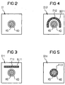
- the cable core KS first a first input disk S1 fed, which is only the central, approximately circular Through opening KD (compare their cross-sectional image in Figure 2) for transverse axial guidance of the cable core KS. Its inside diameter is advantageously about the same Outside diameter of the cable core selected.
- the film F1 is preferably fixed Supply spool VS1 removed and over deflecting means UR1, in particular a deflection roller, brought into a web, which is approximately parallel to the straight longitudinal extension the cable core KS runs. Along this walk the film F1 at a defined radial distance from the Outer surface of the continuous cable core KS held, i.e. it does not yet come into contact with the KS cable core.
- the film F1 is designed essentially flat. Along this straight line is assigned to a specially assigned separate through-opening SL11 in the second molding disc S12 fed and pulled through there.
- This through opening 3 shows schematically SL11 for the film F1 in cross section. It preferably has an approximately flat rectangular inner contour, i.e. it forms a flat rectangular slot.
- Your headroom corresponds preferably approximately the strip thickness of the film F1.
- Your Passage width is expediently approximately equal to the bandwidth slide F1 selected. This will slide the F1 Pass through flat or even laid out and thus one defined initial shape - here as a narrow rectangular shape Band assigned.
- the film is in the Figure 3 labeled F11.
- the slot SL11 above the central through opening KD i.e. with transverse spacing to this, in the shaped washer S11 let in.
- Its broad side runs in the cross-sectional view of Figure 3 viewed essentially in parallel and with Distance to that tangent on the outer circumference of the circular Passage KD, which is assigned to the 12 o'clock position there.
- the film F1 preferably has a bandwidth on that roughly the outer circumference of the one to be encased Cable core corresponds. It is particularly useful that Band width of the respective film slightly larger than that To choose the outer circumference of the cable core KS to be covered, see above that a foil longitudinal tube with overlapping Band edges and thus a completely closed, i.e. in Envelope that is largely sealed circumferentially and longitudinally can be formed.
- the Inner diameter of the central through opening KD expediently approximately equal to the outer diameter of the Cable core selected.
- the inner contour of the film passage opening BS11 to the respective outer contour of the cable core to be covered adapt.
- the S11 to Form washer S12 still does not come with film F1 the continuous cable core KS in contact, but will without touching the KS cable core Discharge direction AZ along and essentially half-shell-shaped, especially to an approximate one Formed semicircular cylindrical film structure.
- the cable core is also the guide for this shaped washer Inner diameter of the central through opening KD expediently approximately equal to the outer diameter of the Cable core selected.
- the semicircularly shaped film F12 (see FIG. 4) then becomes the central through opening in FIG KD of the following shaped disk S1n fed.
- the film F1 lies tubular, in particular circular cylindrical, around the cable core KS and only made contact here, i.e. after and / or upon completion of your desired Geometric shape the outer surface or lateral surface of the Cable core.
- This state of the tubular formed film is designated by F13 in FIG.
- the inside diameter the central through opening KD is preferred slightly larger than the outer diameter of the KS cable core chosen to make room for the subsequent application of the finished to have shaped foil F1 on the cable core KS.
- the inner diameter is the central one Through opening KD between 1.01 and 2.0 times, in particular between 1.01 and 1.05 times larger than the outside diameter the cable core KS selected.
- the film F1 can, in particular, be about one circular cylindrical longitudinal tube with overlapping Band edges have been formed. It can be just as useful be the film with the help of the shaped disks to a longitudinal tube with abutting band edges or to one Longitudinal slot tube with band edges set at a distance to reshape.
- each film expediently a plurality of forming elements along the straight longitudinal extension of the Cable core KS at defined longitudinal distances arranged sequentially.
- these several forming elements each have their own assigned, separate guide opening, i.e. a separate one Passage, for the film to be reshaped.
- the each film is thus during its forming process spatially separated from the cable core. It is particularly useful, at the same time in the respective forming element also a separate through opening for the one to be covered Provide cable core.
- the through openings for the Foil in the forming elements are expediently such chosen that the film successively, in particular continuously formed into the desired geometry can be.
- the film For longitudinal application of at least one film like e.g. F1 to at least one continuous elongated cable product (such as the cable core KS) the film is moved along an assigned forming path like e.g. TL1 separate from the continuous cable product guided along and around the cable product to one Longitudinal film tube such as FR1 molded around. Only then, i.e. after film formation is completed, the so formed, i.e. fully formed foil longitudinal tube FR1 in contact with the continuous cable product KS.
- an assigned forming path like e.g. TL1 separate from the continuous cable product guided along and around the cable product to one Longitudinal film tube such as FR1 molded around. Only then, i.e. after film formation is completed, the so formed, i.e. fully formed foil longitudinal tube FR1 in contact with the continuous cable product KS
- the film can an outer shell of predeterminable geometric shape and especially while largely maintaining this geometric shape be securely attached to the KS cable core.
- the film can an outer shell of predeterminable geometric shape and especially while largely maintaining this geometric shape be securely attached to the KS cable core.
- the guide or forming means such as S11 with S1n are preferably along the section or the partial length section TL1 for predeterminable, consecutive intervals Longitudinal locations in a straight line in a row arranged.
- the section TL1 preferably extends between 10 and 2000 mm, in particular between 100 and 600 mm.
- Two adjacent guide means are preferred at a distance between 10 and 1000 mm, in particular between 50 and positioned 300 mm.
- the Forming section TL1 subsequent, second forming section TL2 is the second film F2 with the help of another series of Shaped discs S21 with S2n in an analogous manner to the first film F1 shaped around the cable core KS and onto it as a longitudinal film tube with a predefined cross-sectional shape upset.
- the originally flat film F2 in Figure 1 withdrawn from its supply spool VS2 and over Deflection means UR2, in particular a deflection roller, in a Longitudinal extension of the cable core KS preferably approximately parallel running course brought.
- the film F2 is replaced by a rectangular slot SL21 pulled through the guide element S21 (see FIG.
- the SL21 slot is now the lower half of the outer circumference of the central through opening KD assigned, in particular by about 180 ° on The outer circumference of the through opening KD is offset, and thus on the opposite side of the through hole KD like that Slit SL11 arranged for the first film F1. She points a defined radial distance from the central one Through opening KD.
- the inner diameter of the central one Through opening KD expediently about the same Outside diameter of those covered with the first film F1 Cable core selected.
- the film F2 With the help of the rectangular slot SL21, the film F2 becomes a defined, flat position assigned, which is labeled F21 in FIG.
- undeformed State F21 of the second film F2 is made using the subordinate guide washer S22 in one Semi-circular shape that the film F2 through a slot BS21 with a semicircular inner contour.
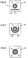
- This through opening BS21 is shown in FIG Cross section drawn. It encloses the central one Through hole KD semi-circular from below, i.e. she is opposite the arcuate slot BS11 of the first film F1 offset by about 180 ° in the circumferential direction.
- the slot BS2 surrounds the central through opening KD thus approximately in the form of a horseshoe and assigns her a predeterminable radial distance.
- the bandwidth of the film F2 is preferably about the outer diameter of the to be covered Jardinseele KS chosen to approximate from it circular cylindrical film tube around the To be able to shape cable core.
- the inner diameter of the central one Through opening KD expediently about the same Outside diameter of those covered with the first film F1 Cable core selected.
- the second film F2 starting from the arcuate, in particular semi-toroidal through opening BS21 inclined inwards to the central through hole KD of the downstream forming element, in particular the shaped plate S2n.
- the foil F2 - as already shaped Longitudinal tube as a second covering layer all around with first tubular film F1 covered cable core, i.e. first there comes the second film tube FR2 with the continuous one Cable core in contact.
- the shaped disk S2n is preferably an inner diameter chosen, which is about twice the layer thickness of the two to be applied foil layers enlarged outer diameter of the Cable core corresponds. This allows the location as well Cross-sectional shape of the finished, formed second film immediately secure them on the first film layer after they are seated.
- the second film F2 along to the film tube FR2 the forming section TL2 is formed around the cable core KS, is ensured with the help of the forming elements F21 with F2n, that the first film tube FR1 its predetermined cross-sectional shape maintains and does not rise. Because the one with the first cable tube FR1 covered cable core KS is in the central through opening KD of the shaped washers F21 with F2n each supported radially from the outside and thereby in the circumferential direction, in particular, secured in a transverse axial position.
- the cable core KS can thus be of a double, tubular Surround foil arrangement of defined cross-sectional shape.
- the cable core covered in this way is shown in FIG KS * designated.
- Figure 8 shows schematically in cross section Positional relationships for those with the two foils F1, F2, respectively tubular cable core KS represents. In this final state are the tube-shaped foils F1, F2 with FR1 as well Designated FR2.
- first and the second Foil F1, F2 each formed into a tube and onto the cable core KS applied lengthways.
- These tubular foil wrappers each preferably have one in the longitudinal direction AZ essentially straight-line overlapping area of their band edges. If necessary, it can also be appropriate, the band edges of the respective film only to be abutted or a tubular covering with an essentially straight longitudinal slot to build.
- the overlap area is preferably in this case or the longitudinal slot of the second, outer film tube FR2 by about 180 ° on the outer circumference in relation to the overlap area or longitudinal slit of the first, inner film tube FR1 offset so that the overlap area or Longitudinal slit of the first film tube FR1 from the second Foil tube FR2 is covered on the outside.
- the foils F1, F2 are spatially separated from each other along two successive forming sections TL1, TL2 formed into foil longitudinal tubes FR1, FR2 and sequentially applied lengthwise to the cable product.
- the foils such as F1, F2 along approximately the same forming section such as.
- TL1 spatially separated from each other in layers one on top of the other to form longitudinal tubes FR1, FR2 to shape the cable product around.
- These one into the other nested longitudinal foil tubes such as FR1, FR2 then at about the same longitudinal location at the same time Cable product applied lengthways.
- the Longitudinal film tubes coaxial with each other.
- the cable core KS * surrounded by the two film layers is additionally guided along an elongated support tube RO when it enters the extruder EX.
- This support tube RO preferably has an inner cross-sectional shape which corresponds to the desired cross-sectional shape of the foil-covered cable core KS *, ie the inner profile of the support tube RO is expediently adapted to the outer profile of the respective foil-covered cable product.
- it is preferably circular cylindrical.
- Its inside diameter is preferably chosen such that the cable core KS * is supported radially from the outside in relation to its central axis ZA.
- the two-layer covered cable core KS * can be introduced into the extruder EX in a substantially stable manner, without causing unacceptable changes in its cross-sectional shape.
- the additional support or guide tube RO thus ensures stable guidance of the cable core KS * with the tubular films. It preferably extends at least as far into the extrusion die head and supports the cable product surrounded by one or more foils radially from the outside until the outer jacket AM is extruded on, thereby causing the foils to be permanently fixed in position. It may be expedient, in particular, to have the support tube RO extend from the outlet of the last shaping disk S2n into the extrusion die.
- the support tube thus largely prevents the film longitudinal tubes FR1, FR2 from opening before the outer jacket AM is applied, their cross-sectional shapes being changed in an impermissible manner or even being destroyed.
- the additional guide or support tube RO thus has the effect that the geometric shape of the respective longitudinal film tube around the cable core is maintained.
- it can be designed such that the foil-wrapped cable core KS * at its tube end in the radial direction post-compressed , ie is final formed.
- the plastic sheath AM for fixing the position of the longitudinal film tubes is extruded directly onto this final formed, foil-covered cable core KS *.
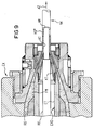
- FIG 9 shows schematically and enlarged in longitudinal section the extruder spray head of the extruder EX of Figure 1.
- This Extruder spray head has to lead through the film-covered Cable core KS * of Figure 1 has a central through opening EXD on, which is essentially in the withdrawal direction AZ extends straight.
- the passage opening is EXD first along an entry-side section ET essentially circular cylindrical shape. That includes itself Middle part of KT, the passage of which is in the withdrawal direction AZ tapered and finally along an exit side Section AT in an approximately circular cylindrical Passage passes.
- Its inside diameter is preferred approximately equal to the desired outside diameter of the one to be manufactured Communication cable NK selected.
- the passage opens at an angle from an outside, an annular gap channel RS a, the hot, viscous plastic mass FM the extruder passage EXD supplies, in particular pumps.
- the annular gap channel RS concentrically surrounds the continuous cable core KS *.
- the continuous, with foils In this way F1, F2 covered cable core KS * becomes all around coated with the plastic compound FM and the outer jacket AM educated.
- the support tube RO (ie, generally speaking guide or support elements) extends approximately to the longitudinal location where the annular gap channel RS flows into the central passage EXD. It acts as a lateral, in particular transverse-axial support means that encloses the foil-covered cable core KS * in particular all around, ie around its entire outer circumference. It therefore performs a guiding and position-fixing function for the respective film tube. Furthermore, it may be sufficient to attach the support tube only in the entrance area of the extrusion die, for example only in the section ET, in particular only until the central through opening EXD has narrowed sufficiently.
- the support tube RO therefore expediently extends into the extruder spray head to such an extent that the Closing form , ie the given geometric shape of the respective longitudinal film tube FR1, FR2 can be maintained in front of the extruder EX until the plastic jacket AM is applied.
- the inner diameter of the support tube RO is preferred between 0 and 1 mm, in particular between 0 and 0.58 mm larger than the outside diameter of the foil-covered cable core KS selected.
- the support tube RO preferably has a longitudinal extent between 100 mm and 1 m.
- FIG. 1 shows pro Foil only 3 fixed shaped disks along their Forming path provided until it is applied to the cable core.
- 3 and 15 in particular between 3 and 8 forming elements arranged along the path of the respective film.
- At several forming elements per film path have their Through openings preferably each one Inner contour shape, each approximately a section corresponds to the outer tube contour to be manufactured.
- the inner contour shape approaches Foil through opening from one shaped disc to the next Form disc gradually to the desired final film shape on.
- Figures 1 to 8 refer to only two Foils, each tubular in two in the same operation Covering cap can be applied to the same cable core.
- this principle according to the invention can be arbitrarily applied expand many, preferably at least two, layers of film.
- each film predeterminable forming section are one or several Ummommffen arranged the respective film successively, especially continuously around the cable core a certain, definable cross-sectional geometry shape it around, during the actual Forming process itself, as long as it is at a distance from the cable core hold until the forming process is complete. Only the finished formed foil tube on the cable core put on and brought into contact with their outer surface.
- the forming agent advantageously allows one or more foils in the Longitudinal inlet directly in front of the extruder is clean and geometrical exact, i.e. particularly effective on what is to be covered Cable product, here the cable core KS, apply.
- the foils are initially independent, i.e. without touch or contacting the continuous cable product preformed and then only after the pipe forming on the Cable product put on.
- KS cable core Through this type of film tube production it is particularly easy to do in one Apply several foils to the KS cable core. While in the same guide or forming element respective cable product with a possibly already applied Foil tube is safely guided, can at the same time next film preformed separately and thereby a stable Guiding and preforming this new film to be applied can be achieved.
- This principle also allows in particular extremely high take-off speeds in cable production.
- the communication cable NK with Speeds between 50 and 500 m / min, in particular between 50 and 200 m / min in the longitudinal direction g AZ.
- the respective film can be removed with little friction be so that an impermissibly high film stress or even film tear is largely avoided.
- Such an elongated cable product can preferably by at least one electrical transmission element such as e.g. a single electrical wire, an electrical wire pair, several electrical wire pairs, one electrical ribbon cable, an electrical cable core or the like is formed be.
- the cable product can also be through at least one optical transmission element such as one Optical fiber, an optical fiber loose tube, a Optical fiber ribbon, a fiber optic chamber cable core or other, optical cable core with at least an optical waveguide.
- other elongated goods of cable technology such as e.g. Glass fiber bundle, according to the inventive method can be enveloped with at least one tubular film.
- foil under the term foil are understood in the context of the invention all possible types of tapes that are usually used in cable technology, such as plastic films, foamed plastic films, composite films such as metal-clad plastic films, metal films, textile films or tapes, mica films, paper films, glass fabric tapes, etc. or combinations of these slides.
- Metal foils or preferably metal-clad plastic foils are particularly suitable for electromagnetic and / or electrostatic shielding of individual electrical wires, individual electrical wire pairs or entire electrical cable cores.
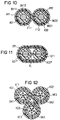
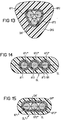
- Figures 10 to 15 each show schematically in cross section different types of cable products or cable elements with different cross-sectional profiles that each with at least one film according to the invention Procedures are enclosed in a tube.
- FIG 10 shows schematically in cross section two electrical Cores AD1, AD2 approximately circular cross-section as elongated Cable elements, each individually with a film F11, F12 surrounded essentially in a ring shape are.
- Each wire AD1, AD2 is approximately circular, Metallic core formed, the outside of which is essentially coaxial surrounded by a firmly attached plastic insulation is.
- the respective film F11, F12 surrounds its core AD1, AD2 in the form of a longitudinal film tube with butt to butt set belt edges BK11 / BK12, BK21 / BK22.
- the respective Foil F11, F12 is on the outer sheath of the associated core AD1, AD2 from the outside through a firmly attached plastic jacket or a plastic coating AM1, AM2 secured the position is substantially toroidal.
- each wire AD1, AD2 is as Foil F11, F12 expediently each have a metal-clad Plastic film, especially an aluminum or Copper-clad plastic carrier film is used.
- the respective foil F11, F12 is with its metal coating preferably turned outside, i.e. it lies with each their plastic carrier film on the outer circumference of the plastic insulation the associated electrical wire AD1, AD2 to ensure reliable electrical insulation can.
- this is Metal coating of foils F11, F12 using a thicker one drawn outer boundary line indicated.
- Such a two-layer single-wire sheath is formed by one film and one outer Plastic coating - can be according to the invention Principle for the two electrical wires AD1, AD2 for example using a device that two wire draw paths lying essentially parallel to one another each with an assigned film forming section (e.g. analogous to TL1 of Figure 1) corresponding to Figure 1.
- the wires AD1, AD2 can therefore be used with one each "Dress" the foil longitudinal tube individually by the Production line of Figure 1 is duplicated, i.e. general expressed:
- Per cable element to be covered is expedient a separate route with one each assigned forming section per film to be applied provided. This allows a variety of cable elements at the same time with at least one foil longitudinal tube individually wrapped or covered.
- the two, each wrapped in two layers (foil plus extrusion layer) electrical wires AD1, AD2 can especially twisted together.
- wires AD1, AD2 their plastic coatings AM1, AM2 directly at or to contact after extrusion. This will cause them to stick together still viscous plastic shells AM1, AM2 together, so that a mechanical connection between the two wires is made.
- an elongated cable element is through an electrical pair of wires is formed. Its two electrical Cores AD1 *, AD2 * preferably correspond to the cores AD1, AD2 of Figure 10 formed.
- In Figure 11 lie their centers on an imaginary, dash-dotted line Straight line VL. They extend vertically to the drawing plane of Figure 11 substantially parallel to each other.
- a common one sits around this pair of wires
- the film is preferred an electromagnetic shielding film selected, the metal layer in the figure 11 is outside and drawn with a thick External boundary line is indicated. About that is Cohesion and to fix the position of the film GF1 common plastic jacket GM1 extruded. Overall is thus an essentially rectangular ribbon with two electrical wires formed.
- This ribbon can preferably with a modified to Figure 1 Production line HV can be manufactured, which only one Foil forming line such as TL2 has.
- the pair of wires AD1 * / AD2 * is then in the forming elements such as S21 with S2n of the foil forming section TL2 of FIG. 1 is expedient each an approximately rectangular passage instead of the central circular through opening KD intended.
- the common Foil GF1 spatially separated from the withdrawal distance of the Wire pair AD1 * / AD2 * around this to a longitudinal tube with approximately rectangular shaped cross-sectional shape.
- forming elements S21 with S2n specifically have the film GF1 assigned through openings, which are now such are profiled that the film GF1 successively to a Longitudinal film tube with an approximately rectangular shape Geometric shape is preformed.
- Foil GF1 with this cross-sectional shape until it is applied of the GM1 plastic jacket on the outer circumference of the wire pair to be able to hold is in the extruder die head of the extruder EX of Figure 1 now conveniently introduced a support tube, its inner contour to the desired rectangular Adjusted outer contour of the foil-covered wire pair AD1 * / AD2 * is. This allows the two ends of the band to be shared Hold film GF1 together until the plastic layer GM1 is extruded.
- Figure 12 shows as elongated cable elements three fiber optic loose tubes BA1 with BA3, each on the individual each a film KF1 with KF3, in particular one Plastic film e.g. for labeling and identification purposes, is applied tubular. Above each film tube there is an extruded plastic cover to secure the position KS1 with KS3.
- the three foil-covered loose tubes BA1 with BA3 are preferred in the three corners of one isosceles triangle arranged so that contact their plastic sleeves KS1 with KS3.
- Figure 13 shows three elongated cable elements or products KP1 with KP3, each symbolically in the form of a hatched circle are indicated. They are triangular in shape arranged and taut in from a common film DKF Form of a foil longitudinal tube with a triangular inner contour as well as the outer contour. Above is to fix the position a common plastic layer DKS with about triangular outer contour DKS applied.
- the production this triangular configuration is preferably carried out accordingly the manufacture of the ribbon according to Figure 11. For this purpose are now the through openings of the forming elements as well of the support tube of Figure 1 to the desired geometry adapted to the triangular group of cable elements KP1 with KP3.
- Figure 14 shows another arrangement of three elongated Cable elements KP1 * with KP3 * to make each one individual a film AF1 with AF3, here in particular one metal-clad plastic film, tubular, in particular approximately circular cylindrical, is laid around.
- the cable elements KP1 * with KP3 * are each symbolic in the form of a hatched circle indicated. For example, they stand representative of electrical wires analogous to Figure 1.
- Die foil-covered cable elements are along an imaginary Connecting straight line GL arranged. They contact you each other.
- each wrapped in film Cable element AD1, AD2 with its own, circular Plastic sheathing AM1, AM2 is the three foil-encased cable elements KP1 * with KP3 * from FIG.
- This Strip material layer in particular plastic layer an essentially flat rectangular outer contour and also sits in the gusset between two neighboring ones Cable elements. This way, one is flat rectangular band element BL formed.
- Applying the Foil of the respective cable element KP1 * with KP3 * can preferably as for the individual electrical wires from Figure 10 can be performed.
- According to the individual Foil wrapping is the individual, foil-covered Cable elements in parallel next to each other and each other brought together in a contacting manner and finally together in an extruder for applying the common ribbon casing BM introduced.
- the support tube has an inner contour on that approximates the outer contour or in particular the envelope of this triple group of cable elements KP1 * with KP3 *.
- a support tube a through opening with a flat rectangular cross-sectional shape on.
- a support tube is particularly useful from the last forming element on the output side to the Extruder extends into it.
- FIG. 15 shows the three cable elements KP1 * with KP3 * from FIG 14 in a further ribbon arrangement.
- You are now with an intermediate distance from each other, i.e. not each other contacting, along the imaginary straight line GL arranged.
- Sits around this group of cable elements now a common GAF film tube with a flat rectangular shape Cross-sectional shape firmly. It is from one common ribbon jacket BM * held together from the outside, which has an approximately rectangular inside and outside contour having.
- the making of such Cable element configuration can preferably be extended that of the two-volume tape of Figure 11.
- the respective film with a predetermined Geometric shape all around the one to be covered Sufficiently secure the cable product in its position. It may therefore be particularly desirable to find a way to demonstrate how at least one slide is around an elongated Cable product with a predefinable geometric shape in can be effectively secured in a simple manner.
- This Object is achieved in that the film to a film longitudinal tube molded around the cable product and onto it longitudinal band edges is applied, and that the both band edges of the longitudinal film tube only with the help of fixations that follow one another in the longitudinal distance to be pinned to one another while between them Fixations remain unconnected.
- the film maintains its predetermined geometric shape to the cable product essentially.
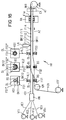
- FIG. 16 schematically shows a device HV in plan view for producing a communication cable according to the invention NK1.
- Supply coils VT1 with VTn become elongated Stranding elements VE1 deducted with VEn and with the help of a Stranding device VN together to form a cable core KS1 stranded.
- elongated stranding elements VE1 with VEn are preferably electrical wires, electrical wire pairs, and other electrical message transmission elements used. In addition or independently of this optionally also optical transmission elements such as Fiber optic, loose tube, Optical fiber ribbons, etc. are used.
- Stranding device VN can preferably be a flat lay stranding machine or SZ stranding machine can be provided.
- the Cable core KS1 is in Figure 1 from left to right in subtracted essentially straight in the pull-off direction AZ. she is only schematic in the form of an elongated Rectangle indicated.
- a foil FO1 is attached to the cable core KS1 in FIG With the help of guiding and forming tools FS1 with FS3 longitudinally applied, in terms of structure, function and Effect of the construction principle of the forming elements from Figure 1 correspond.
- Foil is preferably one electromagnetic and / or electrostatic shielding film such as. a metal-clad plastic film is used.
- electromagnetic and / or electrostatic shielding copper or aluminum coated is particularly suitable Plastic film.
- the foil FO1 is made by her fixed supply spool VTF withdrawn and over Deflection means UM, in particular a deflection roller or the like, brought into a path that essentially parallel to the straight longitudinal extension of the continuous Cable core KS1 runs.
- the forming means FS1 with FS3 are in 1 along an imaginary straight line, that is along the length of the cable core KS1 defined distances in a row.
- This Forming means are preferably as forming disks educated. They each have a central through opening DL for separate passage of the KS1 cable core on.
- the film FO1 is in the each forming element also an independent, separate through opening of a predeterminable cross section.
- the Assignment of the cross-sectional images FS1 * with FS3 * to the Top views of the forming elements FS1 with FS3 are in 1 with a dash-dotted line VL1 VL3 indicated.
- the cable core KS1 is preferably in Form of an approximately circular cylindrical strand educated.
- the central through opening in the forming elements FS1 with FS3 therefore preferably has an approximately circular cross section.
- the inside diameter of the central through opening BL is preferably somewhat larger chosen as the outer diameter of the cable core KS1 to still To have space for later application of the foil FO1.
- the central through opening DL in the forming elements FS1 with FS3 also takes over the function that the cable core KS1 at the longitudinal locations one after the other at intervals experiences defined, stable routing.
- Foil FO1 first becomes one specially assigned, separate through opening RS in the first Forming element FS1 fed and pulled through this.
- This through opening RS is a rectangular slot trained so that the film FO1 designed flat or even can be passed through them.
- the amount of this The slot preferably corresponds approximately to the strip thickness the foil FO1.
- the width of the slot is in particular approximately selected equal to the bandwidth of the foil FO1.
- the Rectangular through opening RS is in FIG.
- the film FO1 wraps around the tube Cable core KS1 around and only contacts here at the third Guide element FS3 the outer surface of the cable core KS1.
- On the path of foil FO1 from its supply spool VTF to to the last guide element FS3 in the series of Foil thus comes with the film continuous cable core KS1 not yet in contact, but becomes independent without touching the cable core KS1 Discharge direction along and continuously reshaped. Only at or after the last management or Forming element FS3 places the formed film tube on the cable core KS1.
- the film FO1 in particular becomes one approximately circular cylindrical longitudinal slit tube rings formed around the continuous cable core KS1 and on this applied lengthways. So the two are facing each other Tape edges BK11, BK12 of foil FO1 on the front with a remaining longitudinal gap or longitudinal slot LI opposite.
- the Band edges BK11, BK12 run in the longitudinal direction of the Cable core KS1, i.e. here particularly straightforward. Consequently the longitudinal slot LI also extends between them in the essentially parallel to the central axis of the KS1 cable core, i.e. essentially straightforward.
- the film FO1 is in particular largely tight stretched the outer circumference of the cable core KS1 and their Belt edges BK11, BK12 in the circumferential direction, i.e. transverse axial based on the longitudinal extension of the cable core, only on the fixations FI1 successive with intermediate gaps mechanically connected with FIn.
- the foil FO1 can in particular be largely seated prevent the foil FO1 from twisting in the circumferential direction or slips in any other, impermissible way.
- the fixings FI1 with FIn can preferably be provided at regular longitudinal distances from one another for fixing the band edges BK11, BK12 of the film FO1 in the circumferential direction. It can also be expedient to provide the fixings FI1 with FIn irregularly distributed in the longitudinal direction.
- the fixings FI1 with FIn secure the position of the film tape sides in the circumferential direction, that is to say transaxially, so that overall the longitudinal tube shape of the film FO1 is retained over the length of the cable core KS1, that is to say the cable core KS1 remains of the film FO1 essentially covered permanently.
- reliable electromagnetic shielding is thus provided.
- an electromagnetic shielding film formed into the longitudinal tube and only fixed at successive locations in the circumferential direction has a higher constancy of its geometric shape as seen over the cable length. This improves the electromagnetic shielding effect, which is particularly important for high-frequency data lines. Furthermore, a film is much more dense and therefore in particular an electromagnetic shielding film is electromagnetic poet as a braid or a weaving of single threads with vacant stitch gaps.
- the cable core covered with the foil FO1 is with the help a haul-off device RA, in particular a caterpillar belt haul-off transported in the take-off direction AZ and finally drummed on the fixed storage drum AT. If necessary, it may be appropriate to use the the cable layer covered with the cable core in the same operation With the help of an extruder according to EX of Figure 1 additionally to be surrounded with a single or multi-layer outer jacket. Such an extruder EX is additional in FIG. 1 dash-dot between the trigger device RA and the Winding drum AT shown.
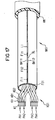
- FIG. 17 shows a schematic and enlarged perspective view of the communication cable NK1 from FIG. 16.
- the cable core KS1 is formed, for example, by four electrical wire pairs PA1 and PA4, which together form a so-called symmetrical star quad are stranded.
- the respective pair of electrical wires, such as PA1 is formed by two electrical wires (conductors), such as AD1, AD2.
- the respective core, such as AD1 has an electrically conductive core KE, such as a metallic wire, in particular a copper wire, in the center, preferably with an approximately circular cylindrical shape.
- This electrically conductive core KE is surrounded all around with an electrically insulating plastic sheath KH, which sits firmly on the core KE in the form of a circular cylindrical insulating jacket.
- the foil FO1 is in the form of a on this cable core KS1 Slotted tube applied, i.e. the film tube closes the cable core all around and sits on it on.
- Their band edges BK11, BK12 are aligned with theirs End faces opposite each other, the longitudinal gap or Longitudinal slot LI lies between them as a narrow parting line. They extend essentially in a straight line and in parallel to the central axis of the KS1 cable core.
- the longitudinal ones Band edges BK11, BK12 are spaced using successive fixings FI1 with FIn with each other mechanically connected, i.e. pinned together.
- the respective Fixation such as FI1 can preferably be achieved with a Gluing or fusion welding of the two band edges BK11, BK12 be formed.
- a fixation of the two abutting band edges BK11, BK12 can in particular caused by the fact that the film at the fixing point is melted and the two edge zones of the foil FO1 in Considered circumferential direction are pressed together, whereby they stick together.
- This is the respective one Fixation in the longitudinal slot between the two, each other opposite end faces of the band edges formed.
- the respective fixation such as FI1 preferably has a larger extension in the longitudinal direction of the cable core KS than in the circumferential direction.
- the Longitudinal expansion of the respective fixation between 1 and 10 times, preferably between 1.2 and 5 times larger than in Circumferential direction.
- Is preferred for the respective fixation a longitudinal dimension of at most 20 mm, in particular at most 10 mm, preferably between 1 and 10 mm, preferred chosen between 1 and 5 mm.
- the film FO1 can be particularly expedient to combine the film FO1 to form such a longitudinal tube in which the band edges BK11, BK12 butt to butt, i.e. as flush as possible in the circumferential direction, are put together.
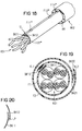
- Figure 18 shows schematically in perspective another way of fixing the geometric shape a foil FO1 *, the cable core in the form of a longitudinal tube KS surrounds.
- Foil FO1 * with overlapping band edges BK11, BK12 the cable core KS is formed into a longitudinal tube.
- the Overlap zone UL of the two band edges BK11, BK12 preferably also extends substantially straight in the longitudinal direction of the cable core KS1.
- the two Foil edges or band edges BK11, BK12 lie along this Overlap section UL one above the other.
- the foil is FO1 * preferably to an approximately circular cylindrical longitudinal tube shaped.
- This fixes this geometric shape causes FO1 * on the top of the film in the area the overlapping halves of each fixation FI1 * with FIn * from the outside in longitudinal distances from each other are upset.
- the respective fixation is in FIG such as FI1 * preferably substantially as about circular spot, especially punctiform.
- the respective fixation such as FI1 * is in the range of Break-off edge of the band edge BK12 lying on top underlying film edge zone BK11 attached. This can it will already be sufficient there in the transition area melt both film edges so that they are together glue, i.e. are pinned together.
- FIG. 19 There is a first, inner film such as F1 around the Cable core KS1 with overlapping band edges BK11, BK12 struck around.
- the two band edges BK11, BK12 are through a fixation KL1, in particular adhesives connected to one another, the between the outside of the inside Band edge BK11 and the inside of the one above Band edge BK12 lies.
- the outside is about that through the Foil F1 formed longitudinal tube another, second foil like e.g. F2 formed into a longitudinal tube.
- Their band edges Like the first film F1, BK21, BK22 are also overlapped.
- Fixing the one above the other Band edges BK21, BK22 of foil F2 is also from the inside brought about by a fixation KL2 in the space between the superimposed band edges BK21, BK22 lies.
- the distribution of fixations for foils F1, F2 is preferably in accordance with FIGS. 16 and 18 in Provided longitudinal direction of the cable core, that is Fixations KL1 of the first film F1 follow at longitudinal intervals on each other. The same applies to the KL2 fixings second slide F2.
- FIG. 20 schematically shows a further possibility in detail, like the overlapping band edges BK11, BK12 the Foil F1 or F2 of Figure 19 mechanically fixed together can be.
- the cross-sectional image of Figure 20 is at the strip edge break the band edge BK12 lying on top Material connection point to the underlying edge zone of the Band edge BK11 set, i.e. it is a cohesive one there Connection with an approximately dot or droplet shape intended.
- Such a material connection can in particular manufactured with the help of a laser welding device be that the frontal area of the overlying Band edge is melted, part of it onto the other, the band edge BK11 underneath drips and adheres there remains.
- the band edge lying on top is preferably BK12 laser-dotted attached to the band edge below.
- the film only in the area of the edge of the melt the overlying band edge BK12 so that the material of the band edge BK12 lying on top with the Material of the band edge BK11 below is mixed.
- the two band edges BK11, BK12 keep pressing until their weld pool sufficiently solidified, i.e. has cooled sufficiently, and thus a solid connection of the strip edges in Circumferential direction is made.
- Figures 16 to 18 relate only to one single film or the figure 19 on two films.
- the Stitching principle according to the invention for fixing the given Geometric shape of the respective film can, however, be based on any number, i.e. expand one or more layers of film.
- FIGS Cable core covered with a film tube Leave it the same way however, according to the principle of the invention other, elongated cable products different Shape, dimensioning and configuration with at least envelop, especially cover, a film tube. So can an electrical wire, for example, as a cable product electrical wire pair, an electrical ribbon cable or a other electrical message transmission element be provided. Likewise, the film wrapping after The inventive method also for cable elements be applied, the at least one optical transmission element exhibit.
- a cable element for example by an optical fiber, a Fiber optic loose tube, an optical fiber ribbon, an optical cable core such as a chamber cable core or, a large number of single optical fibers stranded together be educated. If necessary, that can Cable element also by a group of at least one optical transmission and at least one electrical Transmission element to be constructed.
Landscapes
- Physics & Mathematics (AREA)
- Engineering & Computer Science (AREA)
- Manufacturing & Machinery (AREA)
- General Physics & Mathematics (AREA)
- Optics & Photonics (AREA)
- Extrusion Moulding Of Plastics Or The Like (AREA)
- Manufacturing Of Electric Cables (AREA)
- Shaping Of Tube Ends By Bending Or Straightening (AREA)
- Details Of Indoor Wiring (AREA)
- Finish Polishing, Edge Sharpening, And Grinding By Specific Grinding Devices (AREA)
Applications Claiming Priority (4)
| Application Number | Priority Date | Filing Date | Title |
|---|---|---|---|
| DE19631119 | 1996-08-01 | ||
| DE19631118A DE19631118A1 (de) | 1996-08-01 | 1996-08-01 | Nachrichtenkabel, Verfahren sowie Vorrichtung zu dessen Herstellung |
| DE19631119A DE19631119A1 (de) | 1996-08-01 | 1996-08-01 | Verfahren sowie Vorrichtung zum Längsaufbringen von mindestens einer Folie auf ein Kabelprodukt |
| DE19631118 | 1996-08-01 |
Publications (3)
| Publication Number | Publication Date |
|---|---|
| EP0822562A2 true EP0822562A2 (fr) | 1998-02-04 |
| EP0822562A3 EP0822562A3 (fr) | 1998-11-25 |
| EP0822562B1 EP0822562B1 (fr) | 2003-01-15 |
Family
ID=26028016
Family Applications (1)
| Application Number | Title | Priority Date | Filing Date |
|---|---|---|---|
| EP97112169A Expired - Lifetime EP0822562B1 (fr) | 1996-08-01 | 1997-07-16 | Procédé et dispositif pour enrouler longitudinalement au moins un film sur un produit de câble |
Country Status (3)
| Country | Link |
|---|---|
| EP (1) | EP0822562B1 (fr) |
| AT (1) | ATE231279T1 (fr) |
| DE (1) | DE59709130D1 (fr) |
Cited By (6)
| Publication number | Priority date | Publication date | Assignee | Title |
|---|---|---|---|---|
| GB2441841A (en) * | 2006-09-14 | 2008-03-19 | Technip France Sa | Subsea Umbilical |
| WO2013092933A1 (fr) * | 2011-12-22 | 2013-06-27 | Acome Societe Cooperative Et Participative Societe Anonyme Cooperative De Production A Capital Variable | Câble optique adapte pour mesurer une déformation ou une température |
| WO2020112441A1 (fr) * | 2018-11-29 | 2020-06-04 | Corning Research & Development Corporation | Câble à fibres optiques à gaine soudée et procédé de fabrication |
| CN111498583A (zh) * | 2020-05-26 | 2020-08-07 | 江苏安澜万锦电子股份有限公司 | 一种双排多头铜箔绕带装置 |
| CN114758847A (zh) * | 2021-01-08 | 2022-07-15 | 李政 | 双层纵包模具 |
| US11487069B2 (en) | 2018-11-30 | 2022-11-01 | Corning Research & Development Corporation | Laser welding of cable jacket |
Family Cites Families (2)
| Publication number | Priority date | Publication date | Assignee | Title |
|---|---|---|---|---|
| DE1164529B (de) * | 1962-05-25 | 1964-03-05 | Siemens Ag | Verfahren zur Laengsaufbringung eines Isolierstoffbandes auf einen langgestreckten Kern, insbesondere eines Korrosionsschutzbandes auf einen Kabelmantel |
| US4252584A (en) * | 1979-09-24 | 1981-02-24 | Northern Telecom Limited | Methods and apparatus for wrapping articles of indefinite lengths |
-
1997
- 1997-07-16 DE DE59709130T patent/DE59709130D1/de not_active Expired - Fee Related
- 1997-07-16 AT AT97112169T patent/ATE231279T1/de not_active IP Right Cessation
- 1997-07-16 EP EP97112169A patent/EP0822562B1/fr not_active Expired - Lifetime
Cited By (11)
| Publication number | Priority date | Publication date | Assignee | Title |
|---|---|---|---|---|
| GB2441841A (en) * | 2006-09-14 | 2008-03-19 | Technip France Sa | Subsea Umbilical |
| GB2441841B (en) * | 2006-09-14 | 2009-12-23 | Technip France Sa | Subsea umbilical |
| US9543059B2 (en) | 2006-09-14 | 2017-01-10 | Technip France Sa | Subsea umbilical |
| WO2013092933A1 (fr) * | 2011-12-22 | 2013-06-27 | Acome Societe Cooperative Et Participative Societe Anonyme Cooperative De Production A Capital Variable | Câble optique adapte pour mesurer une déformation ou une température |
| FR2985041A1 (fr) * | 2011-12-22 | 2013-06-28 | Acome Soc Cooperative Et Participative Sa Cooperative De Production A Capital Variable | Cable optique adapte pour mesurer une deformation ou une temperature |
| WO2020112441A1 (fr) * | 2018-11-29 | 2020-06-04 | Corning Research & Development Corporation | Câble à fibres optiques à gaine soudée et procédé de fabrication |
| US20210263254A1 (en) * | 2018-11-29 | 2021-08-26 | Corning Research & Development Corporation | Optical fiber cable with laser welded jacket and method of manufacturing |
| US11487069B2 (en) | 2018-11-30 | 2022-11-01 | Corning Research & Development Corporation | Laser welding of cable jacket |
| CN111498583A (zh) * | 2020-05-26 | 2020-08-07 | 江苏安澜万锦电子股份有限公司 | 一种双排多头铜箔绕带装置 |
| CN114758847A (zh) * | 2021-01-08 | 2022-07-15 | 李政 | 双层纵包模具 |
| CN114758847B (zh) * | 2021-01-08 | 2024-02-20 | 李政 | 双层纵包模具 |
Also Published As
| Publication number | Publication date |
|---|---|
| EP0822562B1 (fr) | 2003-01-15 |
| DE59709130D1 (de) | 2003-02-20 |
| EP0822562A3 (fr) | 1998-11-25 |
| ATE231279T1 (de) | 2003-02-15 |
Similar Documents
| Publication | Publication Date | Title |
|---|---|---|
| DE4304780C2 (de) | Verfahren zur Herstellung eines Koaxialkabels | |
| DE3308482C2 (de) | Flexibler Rohrverbund und Herstellungsverfahren hierzu | |
| DE2932963A1 (de) | Mehradriges kabel sowie verfahren und vorrichtung zur herstellung desselben | |
| DE1640170B2 (de) | Verfahren und maschine zur herstellung eines kabelabschirmrohrs | |
| DE2746929A1 (de) | Verfahren und vorrichtung zum anformen eines metallischen schirms an einen kabelkern | |
| EP2785968A1 (fr) | Procédé de fabrication de l'âme d'un câble, comprenant un conducteur entouré par un joint isolant, destiné à un câble, en particulier à un câble à induction, âme de câble et câble | |
| DE19642542A1 (de) | Vorrichtung sowie Verfahren zur Herstellung eines metallischen Röhrchens für Lichtwellenleiter | |
| DE2755734A1 (de) | Herstellungsverfahren fuer ein lichtleiter-fernmeldekabel und nach diesem verfahren hergestelltes kabel | |
| DE69737989T2 (de) | Verfahren zur Herstellung eines Lichtwellenleiterkabels | |
| EP0822562B1 (fr) | Procédé et dispositif pour enrouler longitudinalement au moins un film sur un produit de câble | |
| DE3537553C2 (de) | Optisches Kabel mit mehreren Hauptbündeln | |
| EP0158730B1 (fr) | Dispositif avec deux accumulateurs tubulaires concentriques | |
| DE3208172A1 (de) | Verfahren und vorrichtung zur herstellung eines grundelements fuer lichtwellenleiter-kabel | |
| EP0927090B1 (fr) | Dispositif et procede de production d'une gaine metallique pour fibres optiques | |
| DE2213653A1 (de) | Verfahren und Vorrichtung zum Abschirmen von Verseilelementen elektrischer Kabel | |
| EP0881730B1 (fr) | Faisceau flexible de tubes | |
| DE3606626A1 (de) | Flachbandleitung mit mehreren lichtwellenleitern und verfahren zu deren herstellung | |
| DE19631119A1 (de) | Verfahren sowie Vorrichtung zum Längsaufbringen von mindestens einer Folie auf ein Kabelprodukt | |
| DE3010353C1 (de) | Optisches Übertragungselement und Verfahren zu seiner Herstellung | |
| DE19713306C1 (de) | Optisches Element oder optisches Kabel und Verfahren zu dessen Herstellung | |
| DE3603713A1 (de) | Verfahren zur herstellung einer lichtwellenleiter enthaltenden bandleitung | |
| DE102020209634B4 (de) | Verfahren zum Herstellen eines Kabelbündels, Fertigungsanlage zur Herstellung eines Kabelbündels, sowie Kabelbündel | |
| DE3635204C2 (fr) | ||
| DE3515717C2 (de) | Lichtwellenleiterkabel und Verfahren zu seiner Herstellung | |
| DE2628946A1 (de) | Verfahren zur herstellung von koaxialkabeln |
Legal Events
| Date | Code | Title | Description |
|---|---|---|---|
| PUAI | Public reference made under article 153(3) epc to a published international application that has entered the european phase |
Free format text: ORIGINAL CODE: 0009012 |
|
| AK | Designated contracting states |
Kind code of ref document: A2 Designated state(s): AT CH DE FR IT LI |
|
| PUAL | Search report despatched |
Free format text: ORIGINAL CODE: 0009013 |
|
| AK | Designated contracting states |
Kind code of ref document: A3 Designated state(s): AT BE CH DE DK ES FI FR GB GR IE IT LI LU MC NL PT SE |
|
| 17P | Request for examination filed |
Effective date: 19990305 |
|
| AKX | Designation fees paid |
Free format text: AT CH DE FR IT LI |
|
| 17Q | First examination report despatched |
Effective date: 20001114 |
|
| GRAG | Despatch of communication of intention to grant |
Free format text: ORIGINAL CODE: EPIDOS AGRA |
|
| GRAG | Despatch of communication of intention to grant |
Free format text: ORIGINAL CODE: EPIDOS AGRA |
|
| GRAH | Despatch of communication of intention to grant a patent |
Free format text: ORIGINAL CODE: EPIDOS IGRA |
|
| GRAH | Despatch of communication of intention to grant a patent |
Free format text: ORIGINAL CODE: EPIDOS IGRA |
|
| GRAA | (expected) grant |
Free format text: ORIGINAL CODE: 0009210 |
|
| AK | Designated contracting states |
Kind code of ref document: B1 Designated state(s): AT CH DE FR IT LI |
|
| REG | Reference to a national code |
Ref country code: CH Ref legal event code: EP |
|
| RAP2 | Party data changed (patent owner data changed or rights of a patent transferred) |
Owner name: CCS TECHNOLOGY, INC. |
|
| REF | Corresponds to: |
Ref document number: 59709130 Country of ref document: DE Date of ref document: 20030220 Kind code of ref document: P |
|
| PG25 | Lapsed in a contracting state [announced via postgrant information from national office to epo] |
Ref country code: AT Free format text: LAPSE BECAUSE OF NON-PAYMENT OF DUE FEES Effective date: 20030716 |
|
| PG25 | Lapsed in a contracting state [announced via postgrant information from national office to epo] |
Ref country code: LI Free format text: LAPSE BECAUSE OF NON-PAYMENT OF DUE FEES Effective date: 20030731 Ref country code: CH Free format text: LAPSE BECAUSE OF NON-PAYMENT OF DUE FEES Effective date: 20030731 |
|
| ET | Fr: translation filed | ||
| PLBE | No opposition filed within time limit |
Free format text: ORIGINAL CODE: 0009261 |
|
| STAA | Information on the status of an ep patent application or granted ep patent |
Free format text: STATUS: NO OPPOSITION FILED WITHIN TIME LIMIT |
|
| 26N | No opposition filed |
Effective date: 20031016 |
|
| REG | Reference to a national code |
Ref country code: CH Ref legal event code: PL |
|
| PGFP | Annual fee paid to national office [announced via postgrant information from national office to epo] |
Ref country code: FR Payment date: 20040720 Year of fee payment: 8 |
|
| PGFP | Annual fee paid to national office [announced via postgrant information from national office to epo] |
Ref country code: DE Payment date: 20040831 Year of fee payment: 8 |
|
| PG25 | Lapsed in a contracting state [announced via postgrant information from national office to epo] |
Ref country code: IT Free format text: LAPSE BECAUSE OF NON-PAYMENT OF DUE FEES;WARNING: LAPSES OF ITALIAN PATENTS WITH EFFECTIVE DATE BEFORE 2007 MAY HAVE OCCURRED AT ANY TIME BEFORE 2007. THE CORRECT EFFECTIVE DATE MAY BE DIFFERENT FROM THE ONE RECORDED. Effective date: 20050716 |
|
| PG25 | Lapsed in a contracting state [announced via postgrant information from national office to epo] |
Ref country code: DE Free format text: LAPSE BECAUSE OF NON-PAYMENT OF DUE FEES Effective date: 20060201 |
|
| PG25 | Lapsed in a contracting state [announced via postgrant information from national office to epo] |
Ref country code: FR Free format text: LAPSE BECAUSE OF NON-PAYMENT OF DUE FEES Effective date: 20060331 |
|
| REG | Reference to a national code |
Ref country code: FR Ref legal event code: ST Effective date: 20060331 |